Benchys on Benches and Sailors on Shelves

Using CAD allowed me to model and then print this custom holder for future benchy calibration test prints.

Using CAD allowed me to model and then print this custom holder for future benchy calibration test prints.

The objectives of this project were to 1) build a 3D model and print from scratch to accumulate hands-on CAD and prototyping experience for future modeling and printing projects, and 2) build a practical object—in this case, shelves resting on the windowsill in the Makerspace that can contain and display Benchys—3D boat models used for calibrating and benchmarking 3D-printing performance.

First, I measured the width of the windowsill (1.5”) and dimensions of a typical 3D Benchy (2.5” x 1.25” x 2.0”). Using those measurements, I used the outline and sketch features in the Fusion 360 software to create a shelf exactly 1.5” wide that would sit flush on our windowsill.

The dimensions of the compartment needed to be slightly larger than the dimensions of the Benchy to allow for movement. So, I sketched a rectangle surrounding the perimeters of the Benchy with an additional .25” of room for the width and height to allow for “tolerance” in the geometric dimensioning. I used the “mirror” action in Fusion360 to duplicate the compartments, totaling 4×4 or 16 shelves.

I sketched a blue rectangle with the same length and height as the Benchy: 2.5” x 2.0”. This served as a helpful tolerancing reference.

I sketched a blue rectangle with the same length and height as the Benchy: 2.5” x 2.0”. This served as a helpful tolerancing reference.

I used the “extrude” feature in Fusion 360 to add a width of 1.5” to the original 2-dimensional sketch, thereby transforming it into a 3D model.

I used the “extrude” feature in Fusion 360 to add a width of 1.5” to the original 2-dimensional sketch, thereby transforming it into a 3D model.


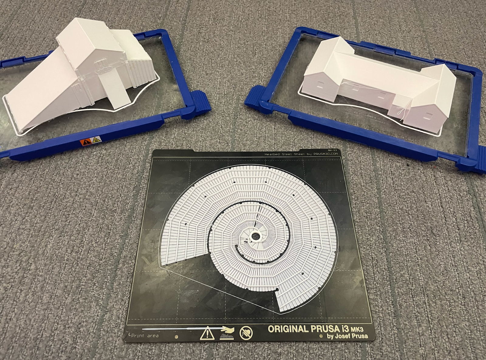
Upon completing the 3D model and initializing the 3D printing process, I discovered that the model’s width and height exceeded the dimensions of the standard Prusa 1 MK3S bed. To solve this problem, I could have undergone another remodeling process to fit the dimensions or sliced the prototype and printed it in four iterations. Instead, I printed the original prototype on the larger Prusa XL. Looking forward to future projects, I’ll carefully consider the geometric dimensions of my 3D models relative to the volumetric constraints of the 3D printing devices to ensure successful prints.

Special thanks to Stepher Sabio (’28) and David Keiser-Clark, Makerspace Program Manager, for assisting in the 3D printing process!

Post Script

One year later, my custom storage shelf is happily filled with calibration test prints by our student workers.

One year later, my custom storage shelf is happily filled with calibration test prints by our student workers.

One year later, my custom storage shelf is happily filled with calibration test prints by our student workers.

Upcycling with Purpose: Breathing New Life into the Makerspace

When you walk into the Makerspace this summer, you might notice a few new additions that don’t quite look “new.” That’s the point.

This summer, the Makerspace team of Divine Uwimana ‘27, Qi Wang ‘26, and David Keiser-Clark, Makerspace Program Manager, brought new meaning to old materials, transforming pieces of Williams history into functional, beautiful tools for creativity and collaboration.

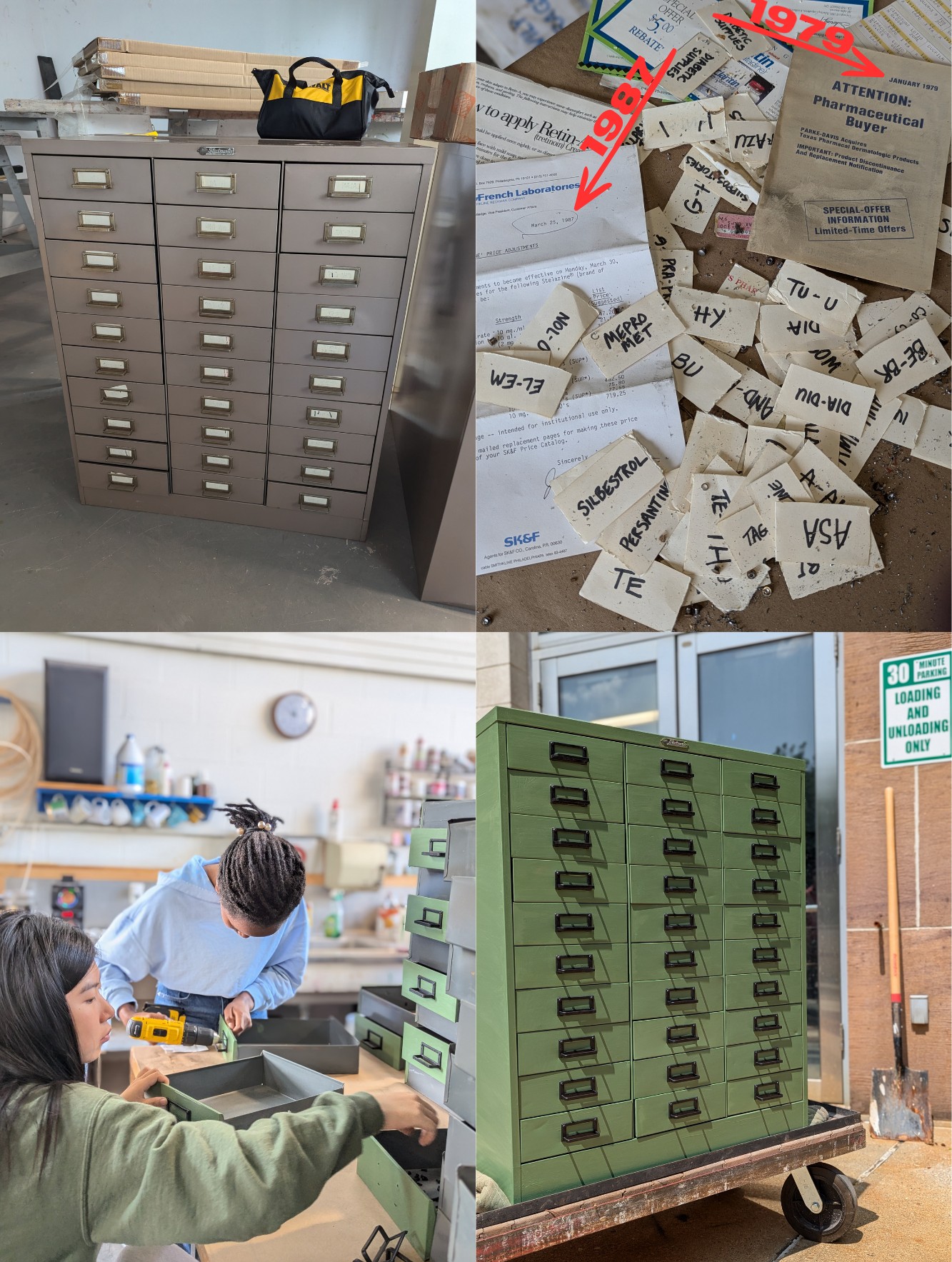
Apothecary Cabinets

Upcycled three apothecary cabinets, rescued from the former Purple Dragon store on Spring Street, and that date back to Hart’s Pharmacy. The photo in top-right is of papers discovered when cleaning and painting the cabinets.

Upcycled three apothecary cabinets, rescued from the former Purple Dragon store on Spring Street, and that date back to Hart’s Pharmacy. The photo in top-right is of papers discovered when cleaning and painting the cabinets.

Take the three apothecary cabinets, for example. These dusty, beige, medicinal storage units were rescued from the former Purple Dragon store on Spring Street—once Hart’s Pharmacy and now just a memory. They now help organize the Makerspace’s growing inventory of electronics, mechanical fasteners, adhesive tapes, small tools, and material supplies in neat little drawers, right where they belong. 

  • Restoration: removed handles, vacuumed, painted with non-toxic Ottosson Linseed Oil Paint
  • Next steps: Collaborate with the Spencer Print Studio and their Risograph (it’s like a Xerox copier that outputs vivid screen prints) to create artistic drawer labels.
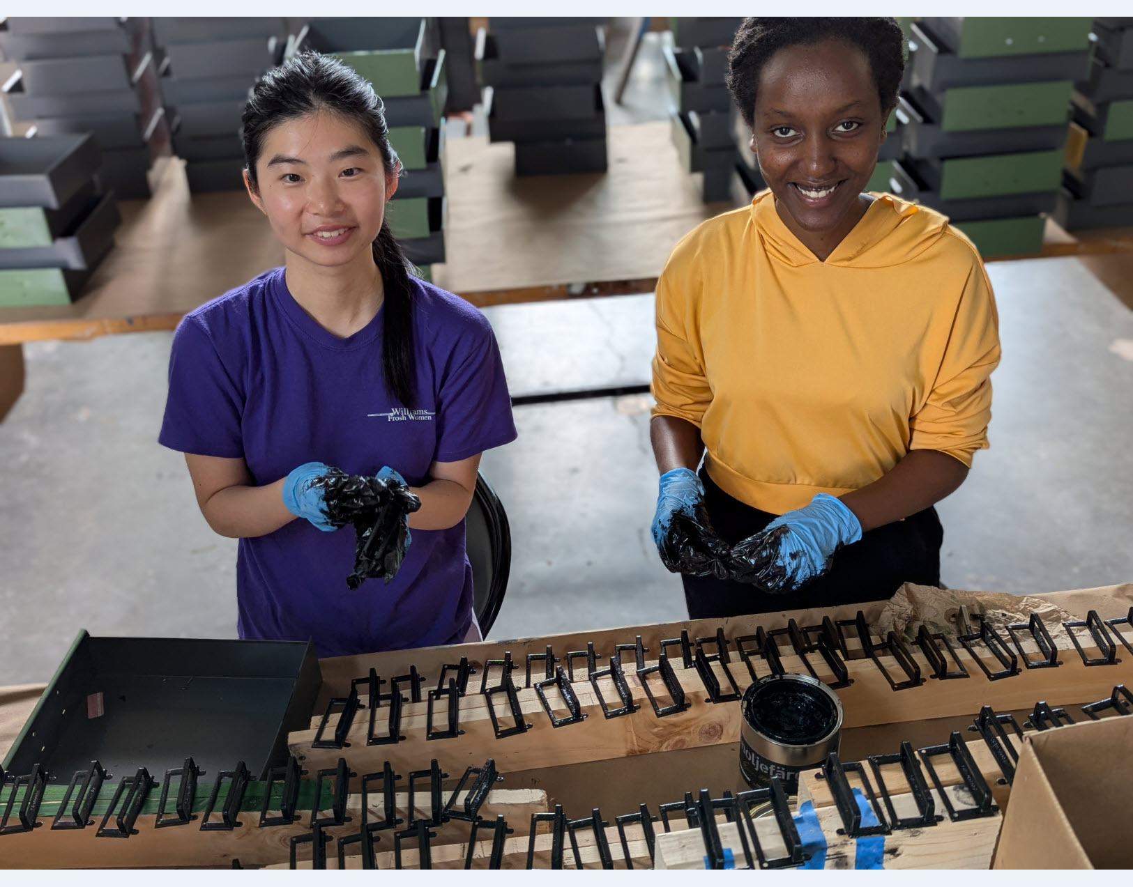
The summer Makerspace team of Divine Uwimana ‘27 and Qi Wang ‘26 transformed these apothecary cabinets.

The summer Makerspace team of Divine Uwimana ‘27 and Qi Wang ‘26 transformed these apothecary cabinets.

Magazine Rack

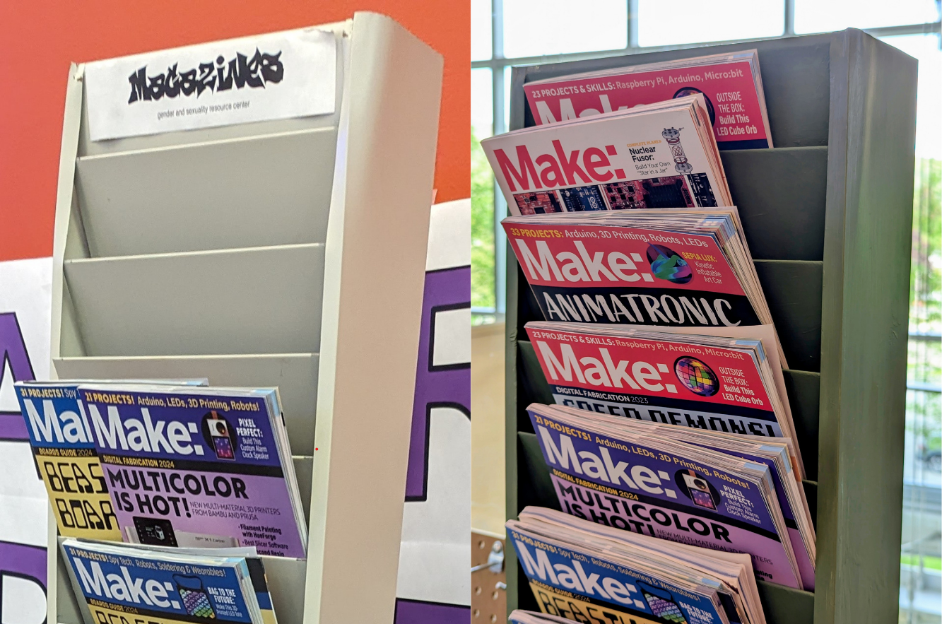
Or the tall metal magazine rack, once tucked away in Room 204 of Bascom House before the Davis Center moved to its new building. Rather than becoming scrap, it’s now a sleek storage solution helping Makerspace users find inspiration through printed guides and materials.

Upcycled one magazine rack from the old Davis Center in Bascom House.

Upcycled one magazine rack from the old Davis Center in Bascom House.

Cubby Organizer

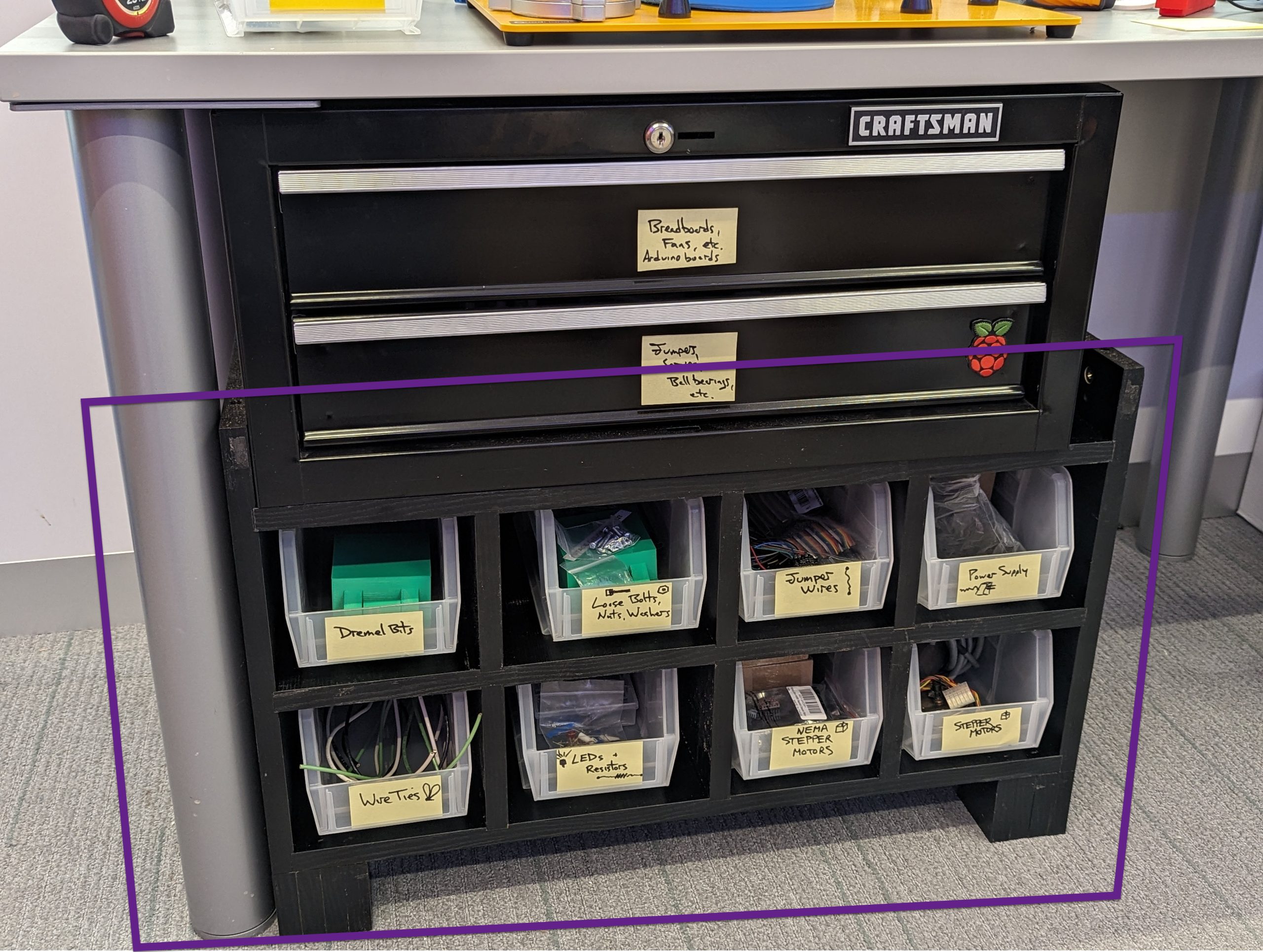
And then there’s the cubby organizer, which tells a particularly satisfying story of transformation. What began as a broken particle board box used to store printer resin was reborn, after a careful sun cure, some table saw finesse, and a lot of ingenuity, into a functional storage cubby, proving that even sticky beginnings can lead to tidy endings.

  • Restoration: Salvaged usable particle board, cut and routered, and reshaped into a purpose built cubby for our organizer trays
Repurposed a broken and trashed particle board box and David recrafted it into the Makerspace's first custom organizer. Less material for the landfill, and it's actively in use.

Repurposed a broken and trashed particle board box and David recrafted it into the Makerspace’s first custom organizer. Less material for the landfill, and it’s actively in use.

Work Tables

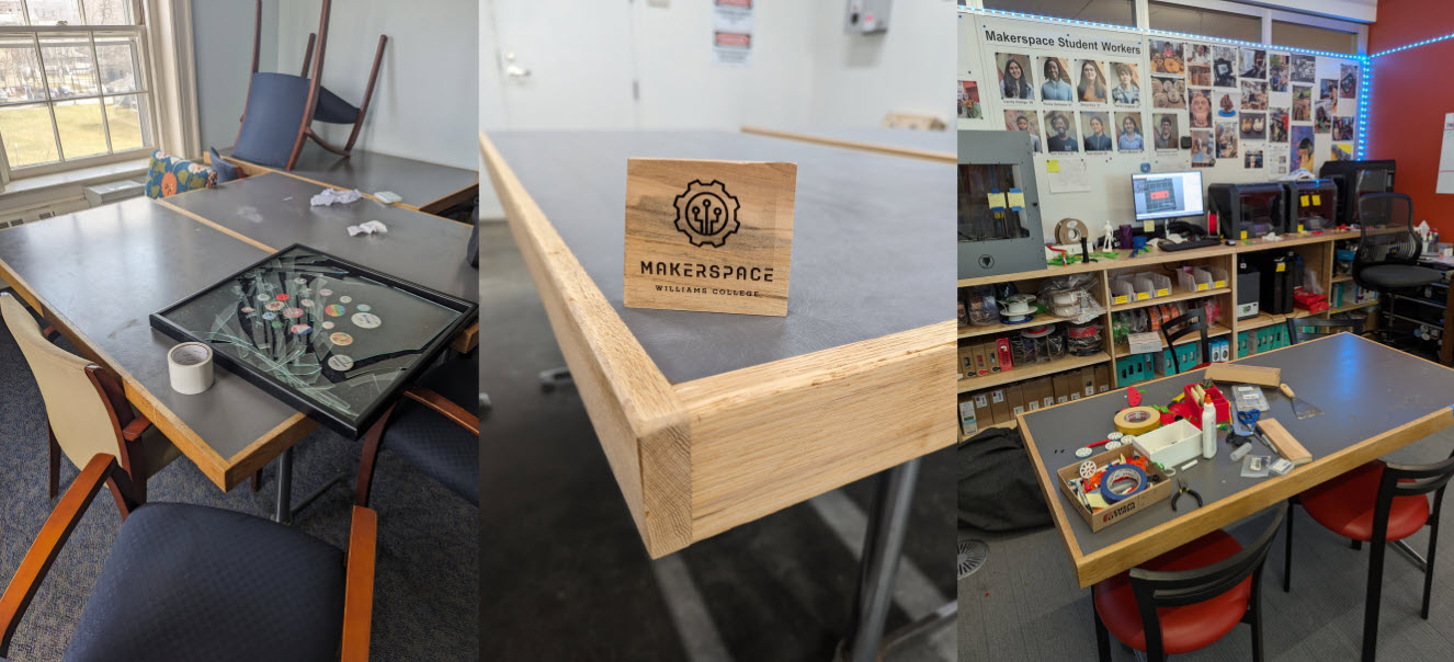
We also welcomed three sturdy tables from Bascom 204, each measuring 60″ by 30″, providing generous surface space for sketching, soldering, and brainstorming. These pieces carry with them the spirit of student collaboration from their previous home and now continue their journey in a space built on invention.

  • Restoration: removed blemishes and splinters by sanding formica top and oak edges, and then our awesome Facilities crew sprayed them with a coat of polyurethane
Repurposed three tables, also from the former Davis Center that was in Bascom House. David sanded, oiled, and applied a topcoat of polyurethane. These tables have never looked better, and are staples now in the Makerspace and FabLab. Zero dollars spent on furniture.

Repurposed three tables, also from the former Davis Center that was in Bascom House. David sanded, oiled, and applied a topcoat of polyurethane. These tables have never looked better, and are staples now in the Makerspace and FabLab. Zero dollars spent on furniture.

Workbench

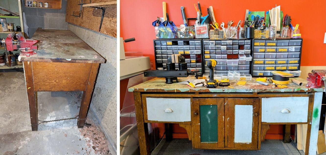
Finally, the new workbench carries a deeply personal legacy. Donated by Carolyn Behr, it once belonged to her late husband Robert “Bob” Behr, Class of 1955. After decades of serving as the heart of his home workshop, it now anchors our own, a quiet nod to generations of builders past and present.

This workbench was donated by Carolyn Behr. It had belonged to her late husband Robert “Bob” Behr, Class of 1955. After decades of serving as the heart of his home workshop, it now anchors our Makerspace, a quiet nod to generations of builders past and present.

This workbench was donated by Carolyn Behr. It had belonged to her late husband Robert “Bob” Behr, Class of 1955. After decades of serving as the heart of his home workshop, it now anchors our Makerspace, a quiet nod to generations of builders past and present.

The Makerspace: Practicing Sustainability

These upcycling projects are more than just practical solutions—they are a reflection of how the Makerspace values sustainability, storytelling, and thoughtful design. Every scratch, label, and drawer has a history. And now, a future.

Stay tuned for more stories like this as we continue to build with care—for the planet, the past, and each other.


Alumni Reunion Weekend at the Makerspace

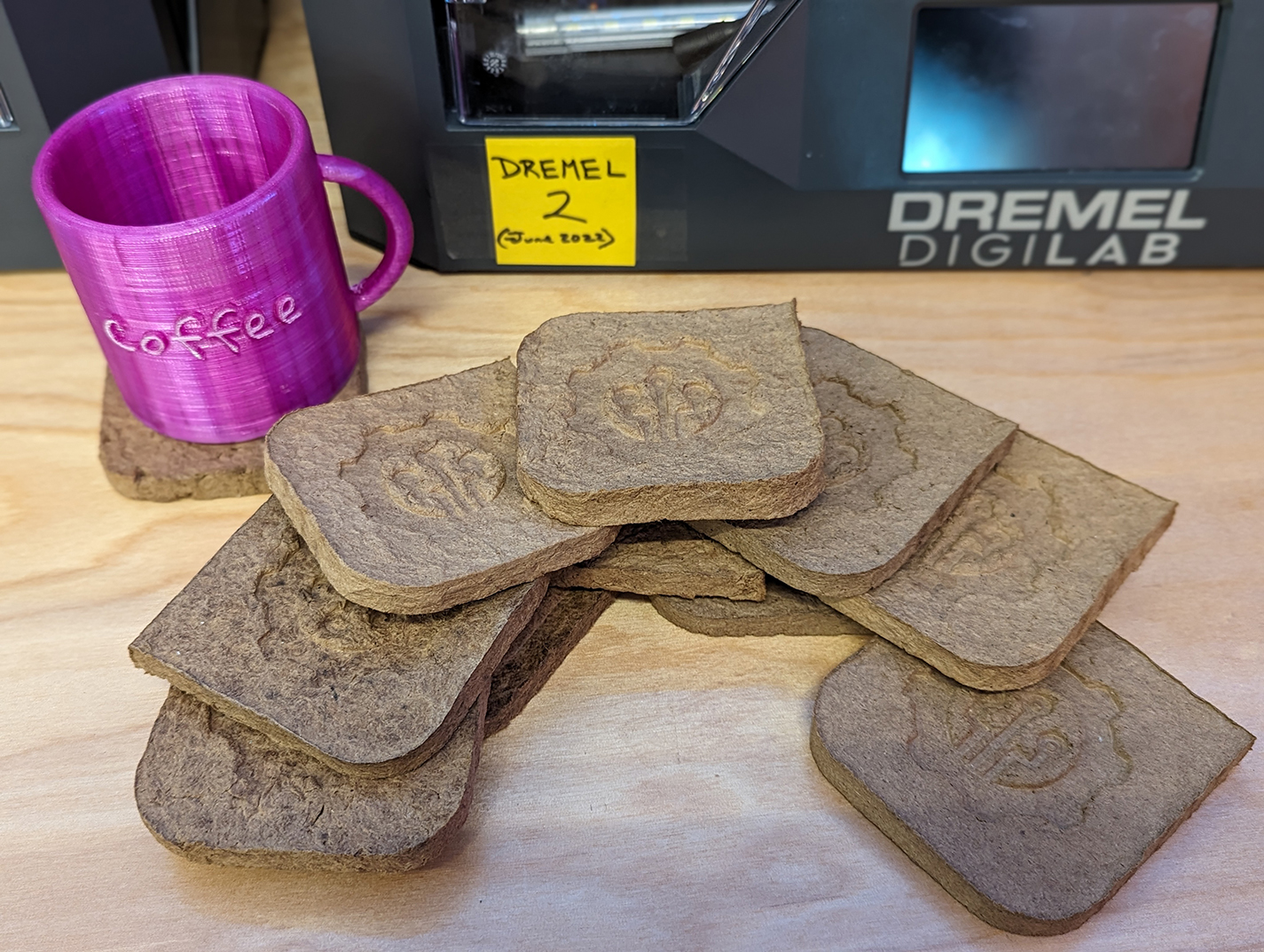
During the sunny and pleasant reunion weekend of June 7th and 8th, the Makerspace was bustling, offering tours and hands-on making experiences to over 200 Williams alums and their families. We prepared a hands-on project that would allow people to use 3D-printed molds to cast Makerspace-themed coasters, sourced from upcycled Amazon cardboard boxes. This fun experience allowed us to share and discuss an environmentally friendly DIY project that people could easily replicate at home. People can even create their own custom molds!

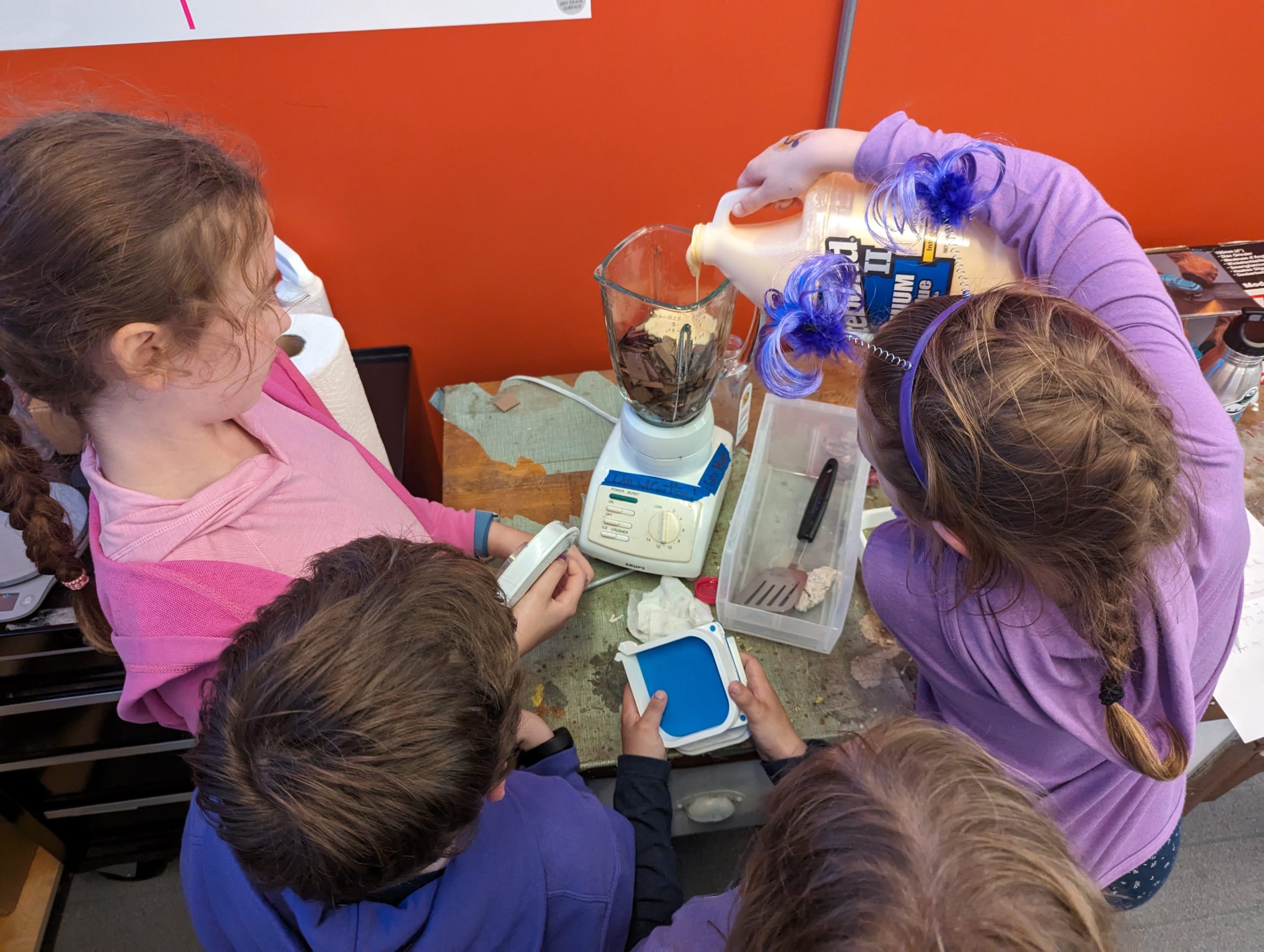
During the alumni reunion weekend, the kids seemed most excited to mix the ingredients, mold the pulp, and finally clamp the coasters. They also got to take home coasters that we had prepared (and dried!) ahead of time.

Alums in the Makerspace on June 7th, 2024

Alums in the Makerspace on June 7th, 2024

Recipe

  • Cardboard boxes (50g)
  • Water (170g)
  • PVA Glue (15g) (we used Titebond II woodworkers glue; Elmer’s white glue works, too)

Tools

Instructions

  • Cut the Amazon boxes into small pieces
  • Add into the blender: 50g of cardboard, 170g of water, and 15g of glue

    The kids were excited to mix the ingredients (cardboard, water, and glue)

    The kids were excited to mix the ingredients (cardboard, water, and glue)

  • Blend until it’s thick and looks like wet clay
  • Assemble the 3D-printed mold: we used and modified this Pulp-it model

    Kids took turns squeezing extra water from the pulp

    Kids took turns squeezing extra water from the pulp

  • Put the pulp in a cheese cloth and squeeze the excess water out
  • Fill the mold with the damp pulp
  • Press the pulp with your hands so that it is dense and evenly distributed in the mold

    And this is how you squeeze the clamps on the mold!

    And this is how you squeeze the clamps on the mold!

  • Attach the lid to the mold
  • Press the mold using a clamp
  • Let it dry for 24 hours
  • Carefully remove it from the mold and gently place it to dry in direct sunlight (or in front of a fan or heater vent) for about 6 hours
  • It should now be 100% dry and solid
  • Nice work!
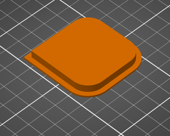
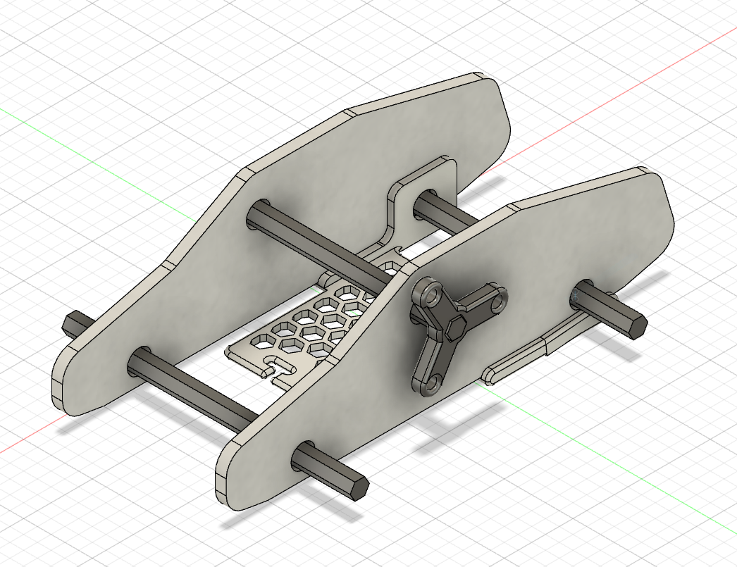
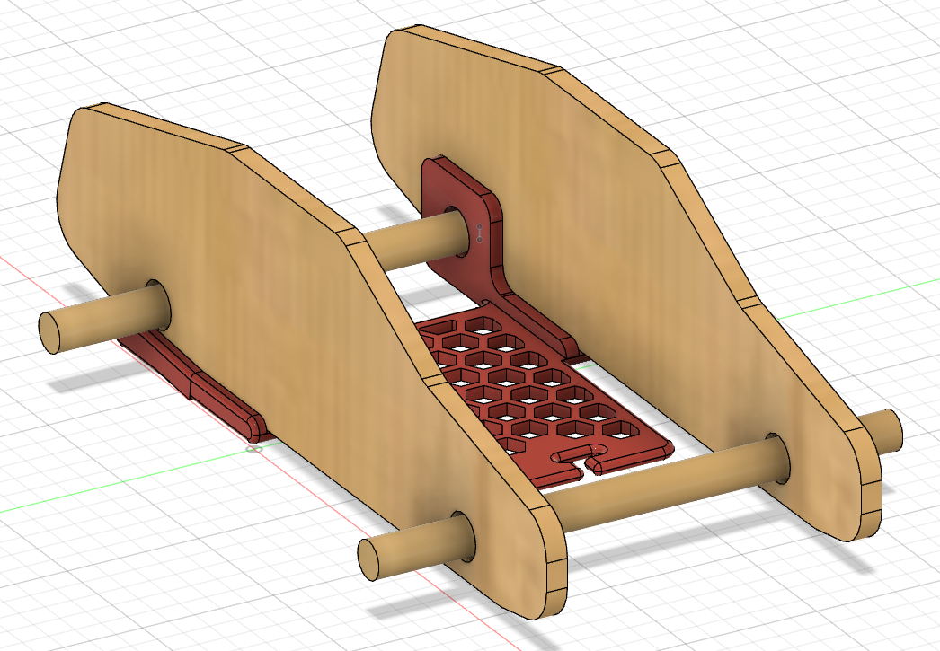
Fusion 360 software: We ended up iterating and tried inverting the extrusion of our design. Which version do you like better?

Fusion 360 software: We ended up iterating and tried inverting the extrusion of our design. Which version do you like better?

The kids had a blast making the coasters while learning about how upcycling minimizes waste in our environment. This activity demonstrated how individual action, no matter how small, may collectively impact positive change.

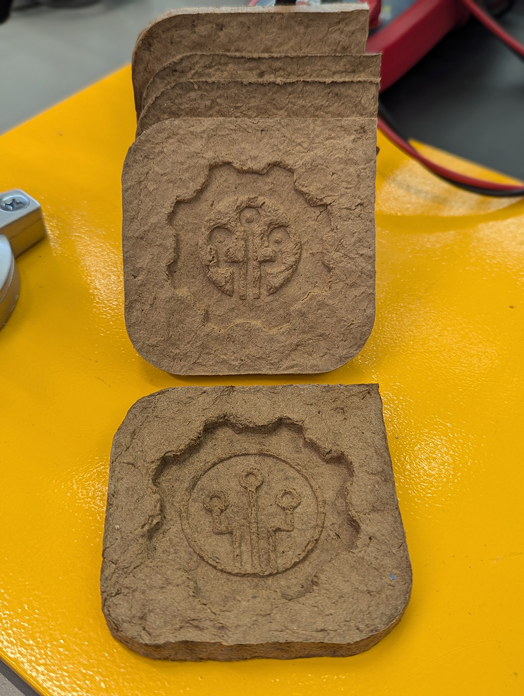
A pile of upcycled coasters made by our alumni's children (from scrap Amazon boxes)

A pile of upcycled coasters made by our alumni’s children (from scrap Amazon boxes)

According to the Environmental Protection Agency

Packaging materials account for 28.1 percent of the total municipal solid waste (MSW), amounting to 82.2 million tons of generation in 2018. This amount poses a high environmental risk and requires systemic and individual actions to mitigate the risks.

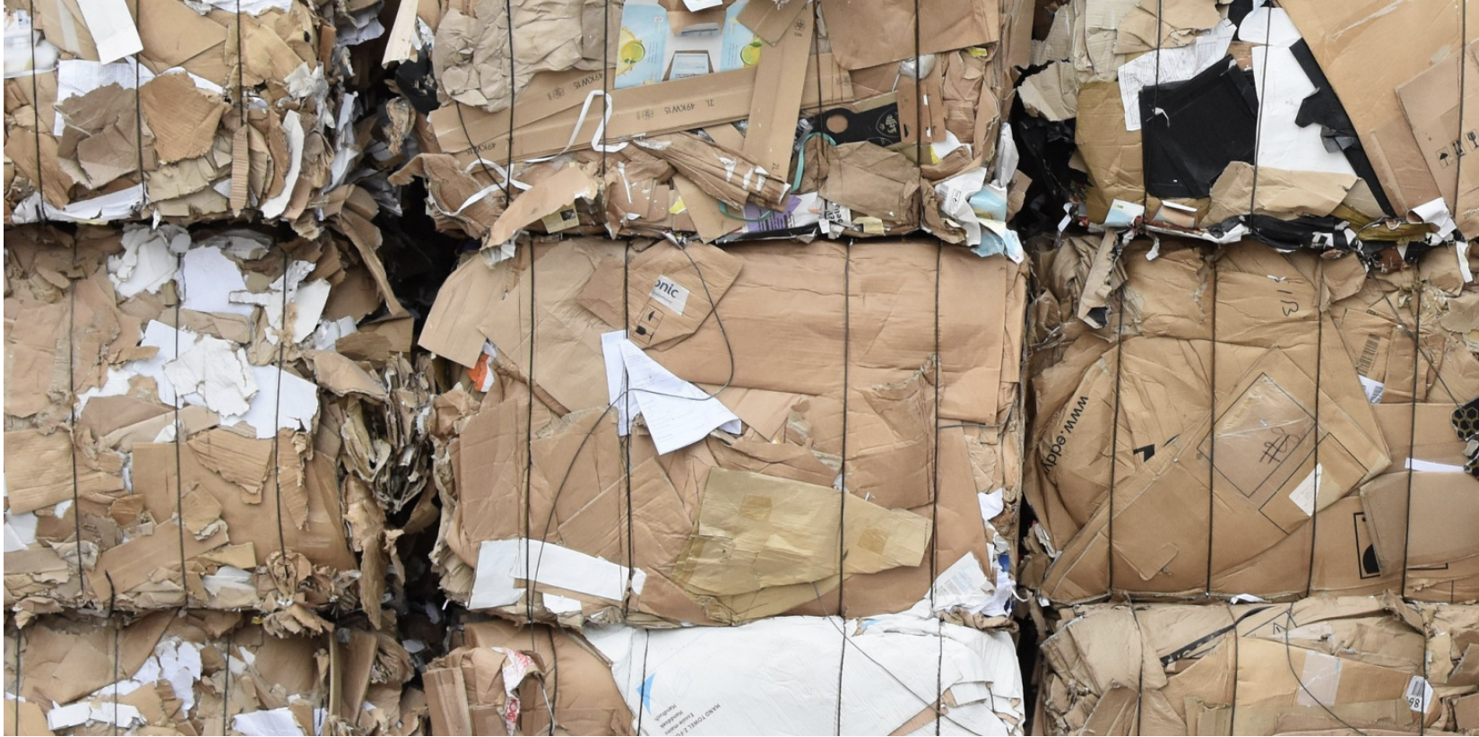
A pile of Amazon boxes

A pile of Amazon boxes

We were inspired by this Pulp-it project, and then we modified their open-source parts by using Fusion 360 software to add the Makerspace logo onto the coaster. To do this, we added an image of the logo and then extruded (raised) it about 8mm. To minimize waste, we tested our prototype models by printing it at 15% of the actual size. 

Fusion 360 software: Before adding our logo

Fusion 360 software: Before adding our logo

Fusion 360 software: After adding our logo

Fusion 360 software: After adding our logo


From Summer Sunshine to STEM Making: Makerspace’s Reflections on a Season of Innovation

Divine Uwimana ’27 and Qi Wang ’26 have an ice cream chat at Spoon Cafe on Spring Street with Makerspace Program Manager David Keiser-Clark.

Divine Uwimana ’27 and Qi Wang ’26 have an ice cream chat at Spoon Cafe on Spring Street with Makerspace Program Manager David Keiser-Clark.

Written by: Qi Wang ’26, Divine Uwimana ’27, Divya Sijwali’ 28.

What happens when you mix a dash of creativity, a sprinkle of STEM magic, and a whole lot of teamwork? Well, welcome to a summer at the Makerspace! Imagine learning how to 3D print parts for a science kit by day and swapping sketches on designs over ice cream by night. 

Divine Uwimana ’27 and Qi Wang ’26 worked in the Makerspace this past summer as student workers. They made significant progress on a Towards Inclusion, Diversity & Equity (TIDE) grant awarded to develop sustainable and reusable STEM learning kits for 5th-grade students in nearby under-resourced elementary schools. 

In the summer, Divine and Qi learned Fusion 360 (computer-aided design software) and advanced 3D printing, including calibrating printers and determining the most appropriate hot-end temperature settings. They identified and associated core curriculum science concepts with their STEM kit models and learned how to use rapid prototyping to test and quickly iterate on conceptual designs. By the end of the summer, they had developed three STEM kit models. Their kits centered on storing variable amounts of potential energy by using 3D printed torsion springs, gravity, and rubber bands. Their goal was for a single set of common parts to support all three models.

What Does Makerspace Mean to Them?

3D printed wind up car with an embedded rubber band power source

3D printed wind up car with an embedded rubber band power source

Divine Uwimana ’27 has worked in the Makerspace since the start of her first year at Williams. Divine believes that the Makerspace has offered her a place to learn and create. She said, “I love seeing the product of my learning, and it’s motivating to know that my summer experience will help elementary students learn.” As a math major, the Makerspace has allowed her to apply her skills in mathematics and be creative with them. She added, “I’ve also learned to pay attention to details and have noticed how you can see a huge difference when you change the smallest detail.” 

While working on this project, Divine felt a deep sense of excitement and responsibility: it was fun to make the kits, but making them for the kids made them more meaningful. Developing these STEM learning kits was a way to blend her skills with younger students’ needs, hoping it would enrich their learning experiences. Every design and every print felt a step closer to making a tangible impact. As she dove deeper into learning Fusion 360 and fine-tuning her 3D printing techniques, she felt a sense of accomplishment in turning ideas into designs and then finally into design models. Seeing the pieces come together was incredibly motivating for Divine; the process showed how small adjustments, like changing the length or thickness of a model or adjusting temperature settings, could make a huge difference in the final print.

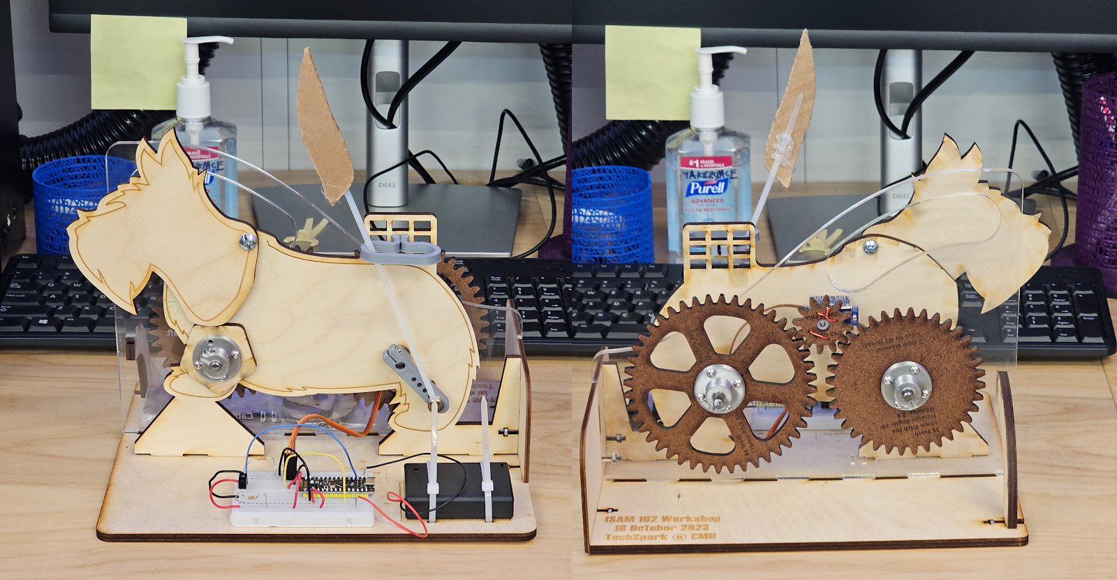
The opportunity to work collaboratively in a focused environment manifested several “aha” moments for Divine. She said that the most notable was having first-time opportunities to assemble a mechanical Scotty dog kit (created at Carnegie Mellon University’s TechSpark Makerspace), a 3D printer enclosure kit, a wall-mounted tool rack, and a DeWalt shop vac. These assembly projects helped Divine conceptualize pieces that go together. It also helped her learn how to approach designing her own STEM kit models.

3D printed gravity-powered car

3D printed gravity-powered car

Qi Wang ’26 started working in the Makerspace this summer. She appreciates the existence of the Makerspace at Williams because of its real-world application. She said, “Williams is a liberal arts college but also very prestigious. The courses here often are very theoretical, while internships trend towards being pre-professional. The Makerspace is a rare space in between these extremes.” As a comparative literature major, she recognizes that Williams’ courses focus on literature critiques rather than creative writing. The Makerspace offers a space for applied hands-on academic work that requires learning how to research and implement STEM concepts while utilizing her creative writing and thinking skills. Qi found this summer work filled a gap that had been missing in her education at Williams.

Qi also points out the invaluable opportunity of full-time summer work in the Makerspace. She said, “During a typical semester, you see progress only after many weeks because you can only work for at most 20 hours a week as a student worker, compared to the summer, where we have been working 40 hours a week. I feel really good about our summer project in the Makerspace because we’re seeing so much success in just over nine weeks of work.”

Qi believes that the connection between Comparative Literature and the Makerspace is a blend of storytelling and science, like finding the plot twist hidden in a machine or crafting a narrative around STEM. In Comparative Literature, she’s used to dissecting stories, examining themes, and understanding every word’s purpose. At the Makerspace, Qi found herself bringing that same attention to detail and creativity to projects, as if each STEM kit was its own story waiting to unfold.

Creating STEM kits is like crafting a hands-on narrative for the elementary students who will one day use them. Just as she analyzes texts to bring out underlying meanings, Qi digs into her projects with a literary eye—considering how each part fits, how each mechanism flows, and how a simple change in design can rewrite the entire “storyline” of a STEM model. The Makerspace offered her a refreshing new way to put her analytical mind to work, letting her blend the theoretical with the practical and transform her love for literature into a hands-on learning journey.

How Was Their Experience Working Together?

Qi believes that working with Divine has been one of the best teamwork experiences she has had at Williams. She said, “We each have our strengths and have learned how to contribute our ideas to each other’s established work. People often love to give advice, but we’ve figured out how to have our advice add value to our ongoing work.” 

“I’ve also enjoyed working on these kits with Qi and learned a lot from her,” Divine said. “She was always willing to help and provide me with honest feedback. She always had a positive attitude and always made the working atmosphere fun and motivating.”  

In the fall semester, they will hand off their work to two first-year students to develop it further. Divine said, “I am looking forward to seeing the impact of our work and to hearing feedback from both students and teachers at the Pownal Elementary School.” 

Makerspace Meets Machine Shop: A Summer Science Program Collaboration

Summer Science Program 2024

Summer Science Program 2024

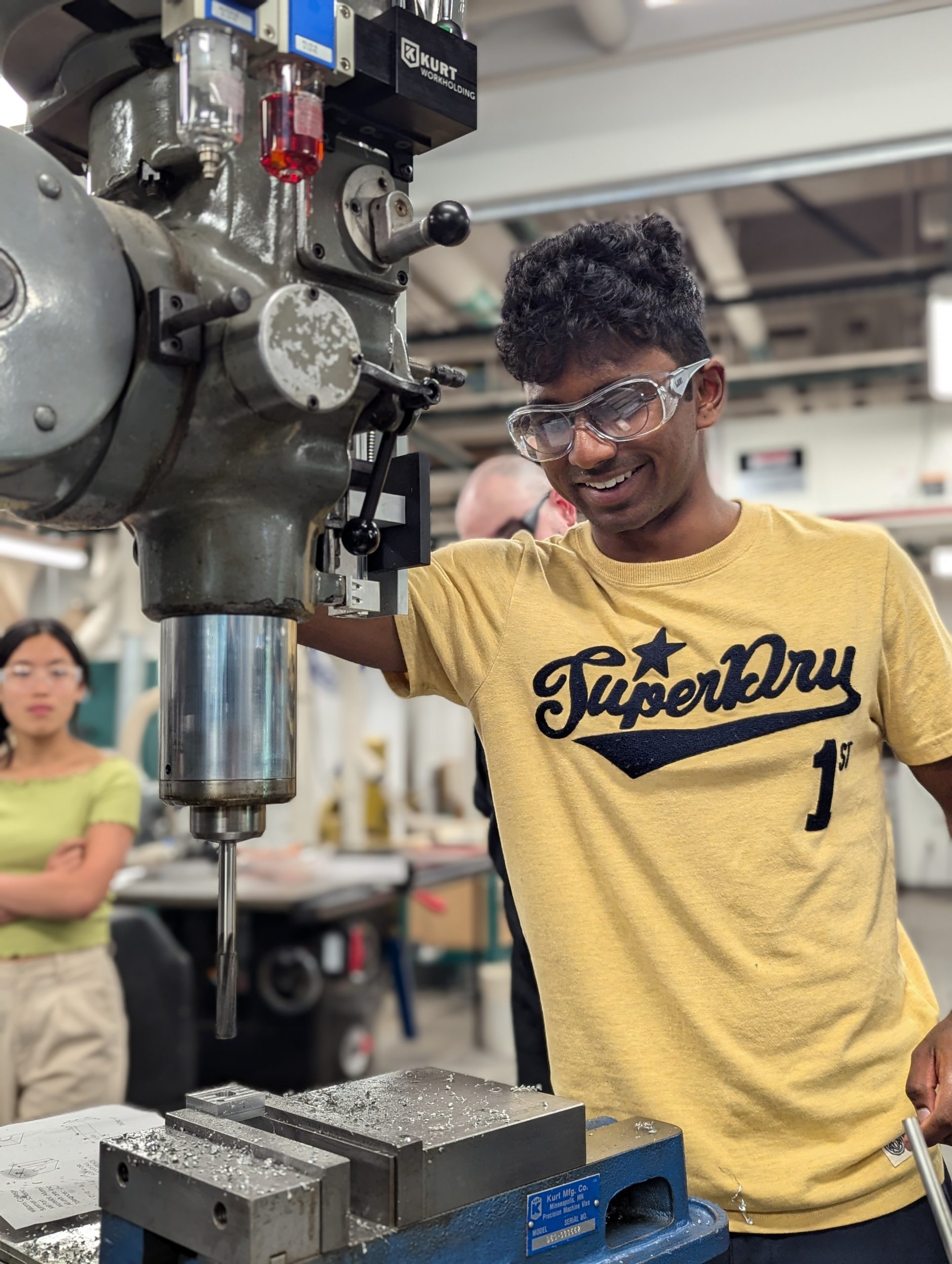
This June, the Williams College Makerspace and the Hopper Science Center’s Machine Shop teamed up to deliver hands-on training for the Summer Science Program (SSP), an intensive experience that welcomes an incoming cohort of about 20 students each year into STEM fields. When Senior Science Center Shop Engineer Jason Mativi found himself short-staffed for the week of June 17–21, Makerspace Manager David Keiser-Clark stepped in to co-teach the course, guiding students through the Bridgeport Mill and metal lathe across five full days of instruction. The partnership came together quickly and warmly: Science Center Director Amy Gehring reached out to Academic Technology Services, and with enthusiastic support from Director Tattiya Maruco and Barron Koralesky, the cross-unit collaboration was approved within hours — a nice reminder of how easily good partnerships can form here at Williams.

Summer Science Program 2024

Summer Science Program 2024

The collaboration turned out to be exactly the kind of teamwork SSP is built on. Jason later shared that he simply couldn’t have run the course without David’s help, praising him as a quick study who picked up the shop’s equipment with ease and helped every student move through the material safely and efficiently. The result was a smoother, more successful week for students and instructors alike — and the beginning of what both hope will be an ongoing partnership between the Makerspace and the Science Shop, with plans to keep building shared skills and expanding what students can learn from both spaces.


Summer Science Program 2024

Summer Science Program 2024

Summer Science Program 2024

Summer Science Program 2024

Summer Science Program 2024

Summer Science Program 2024

Summer Science Program 2024

Summer Science Program 2024


Introducing the Williams MakersWeb

Below is the Daily Message published on Tuesday, July 16th, 2024:

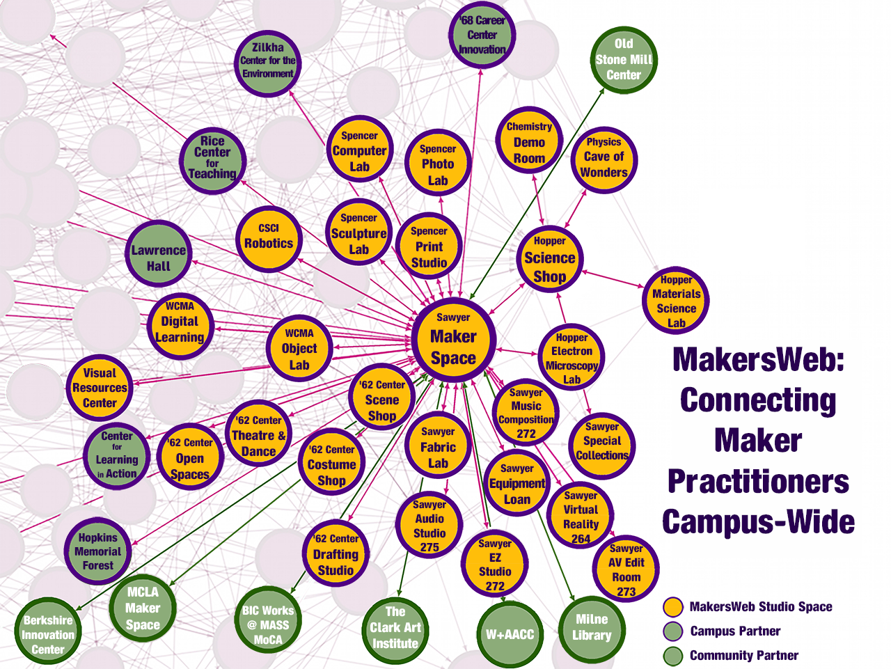
The Williams MakersWeb is a network of staff and faculty expert practitioners that represent the 27 maker spaces and studios distributed throughout campus. It also includes 6 campus and 9 community partners. The MakersWeb embraces interdisciplinary networking as a means to better serve the mission of the College.

The Williams MakersWeb is a network of staff and faculty expert practitioners that represent the 27 maker spaces and studios distributed throughout campus. It also includes 6 campus and 9 community partners. The MakersWeb embraces interdisciplinary networking as a means to better serve the mission of the College.

The Provost’s Office is excited to support the creation of the Williams MakersWeb, a staff-led initiative to improve opportunities for interdisciplinary collaboration between the 20+ creative work spaces on campus.

The MakersWeb offers a monthly forum for staff and faculty “maker” practitioners to share expertise, promote curricular projects and engaged scholarship, and to discuss improving access to making equipment, standardizing safety practices, and conserving resources through bulk purchasing and creating a hardgoods inventory. Meetings will be organized and facilitated by David Keiser-Clark (Makerspace) and Jason Mativi (Science Shop). 

The MakersWeb supports at least three strategic commitments (The Future of the Arts at WilliamsSustainability, and Learning Beyond the Classroom).

I hope that practitioners will participate and that the campus will support this work by dedicated individuals to support the curriculum.

More Information: MakersWeb

Turning Spreadsheets into Skylines: A Makerspace and Zilkha Center Collaboration

Nikhil Radosevich ‘27 created a data expression method for turning spreadsheets into 3D objects

Nikhil Radosevich ‘27 created a data expression method for turning spreadsheets into 3D objects

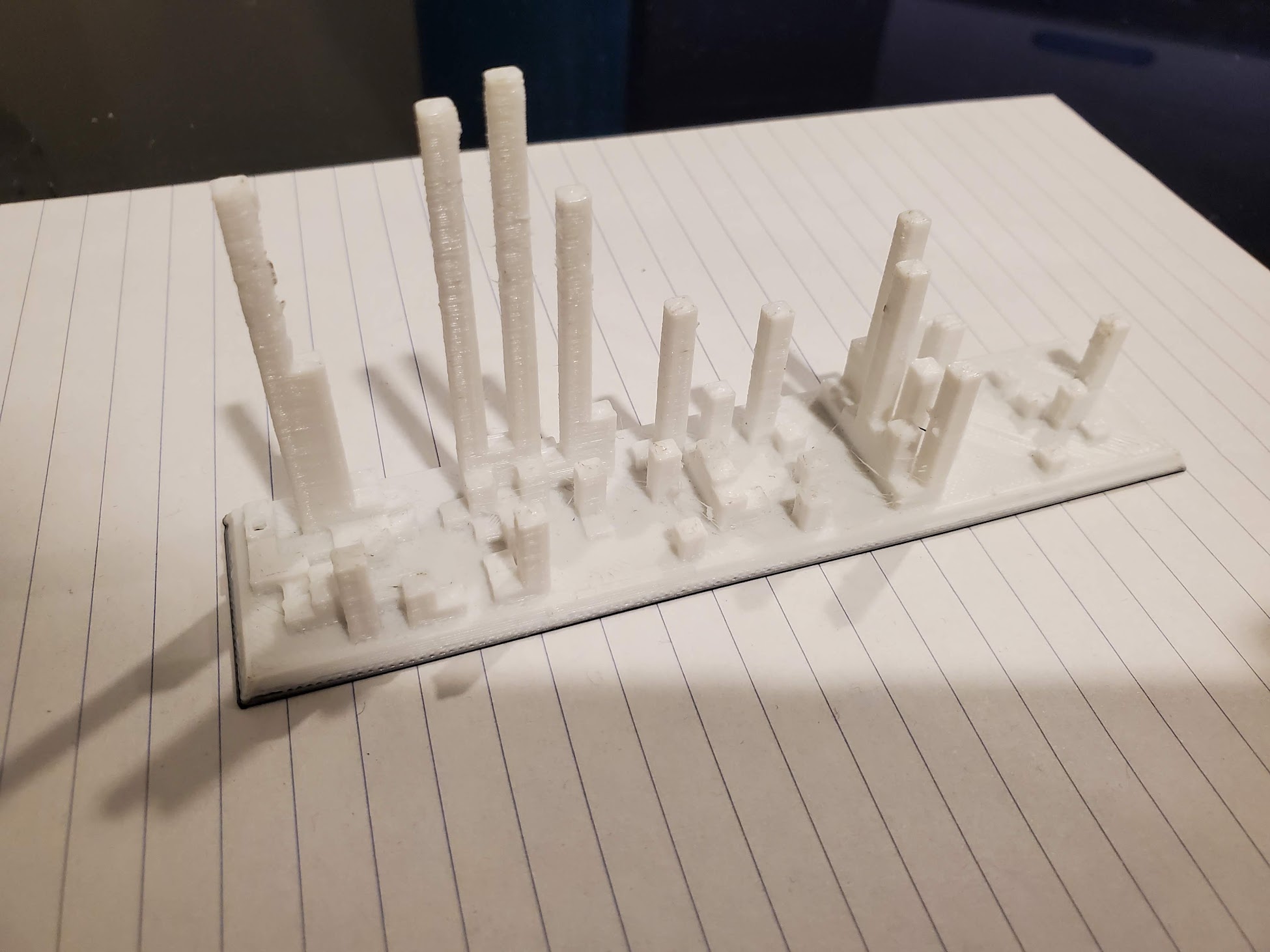
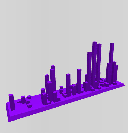
Some students see a spreadsheet and see rows and columns. Nikhil Radosevich ‘27 sees a skyline. Back in high school, Nikhil built a program that turns any spreadsheet directly into a 3D-printable file, and the print pictured above — also featured on the homepage of his site, solidifydata.com — is a perfect example of what that looks like in practice. This 3D printed object represents his own volunteer hours over the course of a year: the height of each column shows how many hours he logged, its position along the width marks the week of the year, and its depth marks the day of the week. Line it all up and a spreadsheet becomes a miniature city skyline you can hold, turn over, and study from every angle — busy weeks rising up like towers next to the quiet stretches in between. It’s a small, clever reminder that data doesn’t have to stay flat on a screen to be understood.

Nikhil Radosevich ‘27 created a data expression method for turning spreadsheets into 3D objects

Nikhil Radosevich ‘27 created a data expression method for turning spreadsheets into 3D objects

Now a student at Williams, Nikhil is applying that same creative instinct to campus sustainability data, and this summer he reached out to the Makerspace hoping to print physical visualizations that the Zilkha Center could share with staff and other stakeholders. Makerspace Program Manager David Keiser-Clark welcomed him back, connecting him with Divine Uwimana ’27 and Qi Wang ’26, who are staffing the Makerspace this summer and ready to help turn his files into finished prints, each taking less than three hours of machine time to produce. David also shared Nikhil’s work with colleagues across campus, including GIS expert Cory Campbell, who may find fresh ways to apply the same approach to spatial data. It’s a nice example of what can happen when a student’s independent project meets the right campus resources: a tool Nikhil built for himself in high school is now becoming a bridge between the Makerspace and the Zilkha Center’s efforts to make campus data something people can see, touch, and talk about.


Spinning Tales : Arduino Turntable Step-by-Step Tutorial (Part 2)

Welcome back to my deep dive into the creation of a low-cost DIY Arduino turntable designed for photogrammetry enthusiasts. In this continuation, I will share a detailed, step-by-step breakdown of the build process, highlighting the technical challenges and solutions, while providing comprehensive resources to empower you to replicate this project.
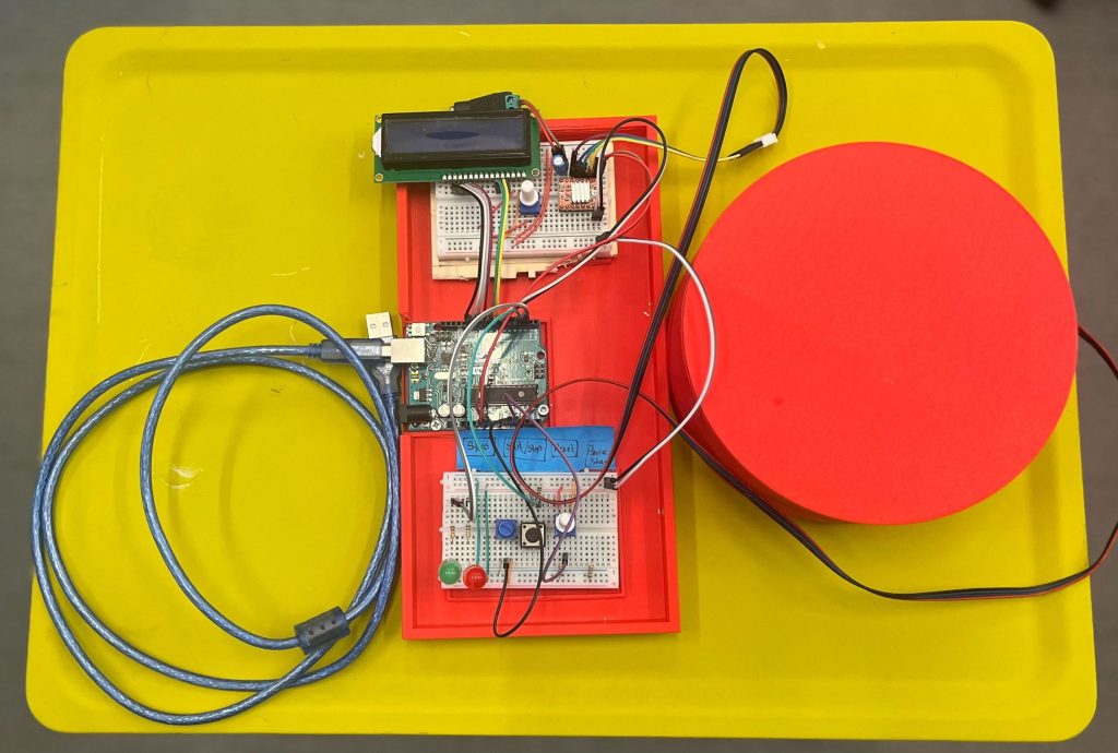
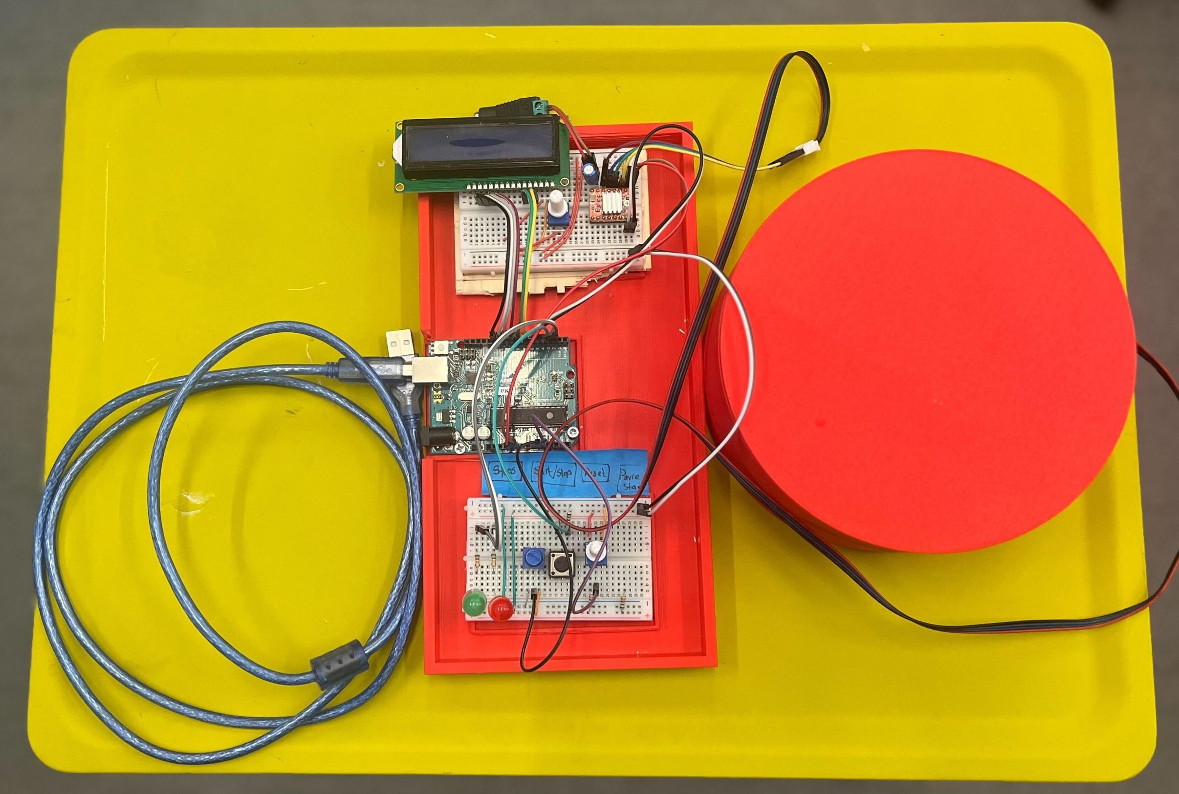
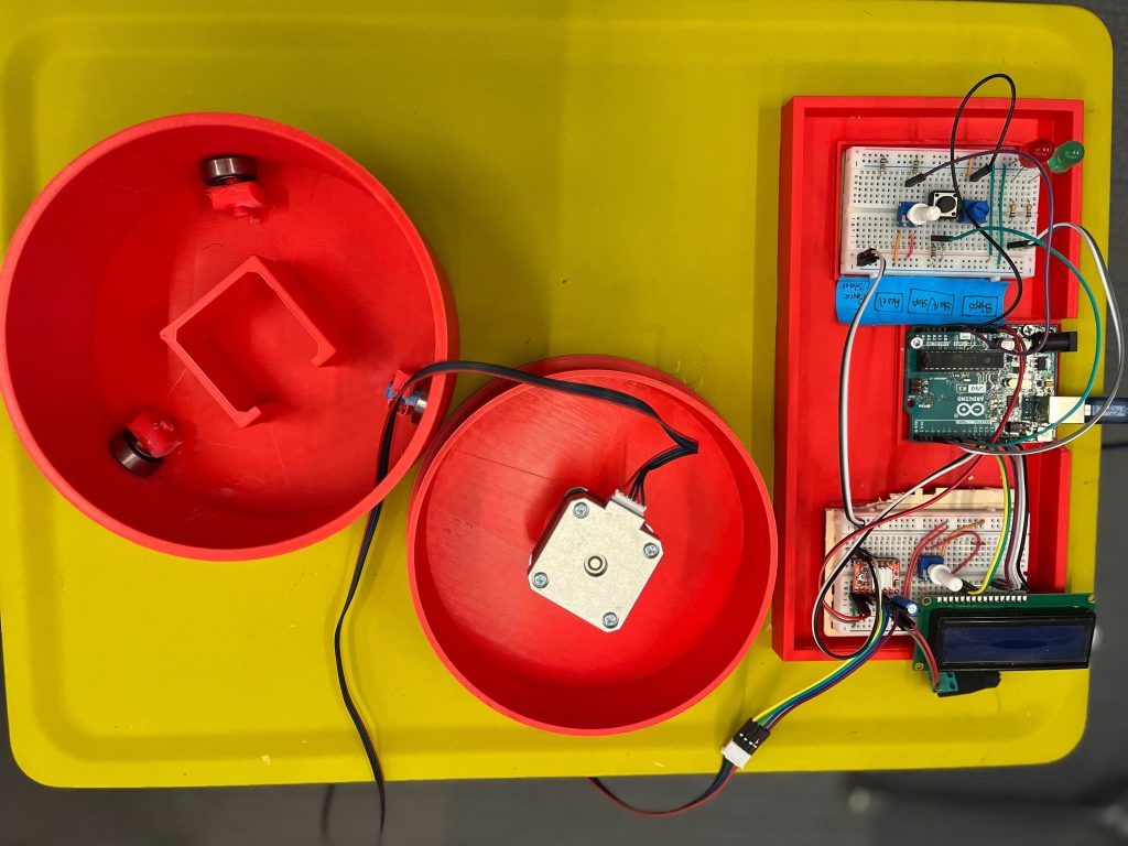
Completed Turntable with the control board

Components

The primary goal was to design a reliable and cost-effective turntable that can be easily assembled by hobbyists. The focus was on using readily available parts and open-source software to keep the project accessible. Below is a detailed component breakdown, including links, for each part needed, for the project:

1. NEMA 17 Stepper Motor
Quantity: 2-3
Why? Chosen for its balance between cost and performance. NEMA 17 offers sufficient torque for precise rotations necessary in photogrammetry without being overly robust for lightweight platform applications. Compared to larger steppers like the NEMA 23, which offers more power but at a higher cost and size, the NEMA 17 is more suited for desktop projects where space and budget are limited.

2. A4988 Stepper Motor Driver
Quantity: 2-3
Why? The A4988 is a reliable and widely used motor driver that offers easy interfacing with Arduino, making it ideal for beginners and intermediate users alike. It supports micro-stepping which is essential for smooth and accurate rotation. Other drivers like the DRV8825 could also be used but typically cost more and require additional adjustments, making the A4988 a more straightforward choice for this project.

3. 608 Bearing 8x22x7
Quantity: 4-6
Why? These standard skateboard bearings are cost-effective and easily available. They are durable and provide smooth rotation with minimal friction, which is crucial for the accuracy of the turntable. Alternative options like specialized robotics bearings offer higher precision but at a significantly higher cost, making them overkill for this application.

4. 12V Adapter with Female Adapter
Quantity: 1
Why? This adapter provides a reliable and stable power source for the project. 12V is typically needed for the stepper motors, and using a dedicated adapter ensures consistent performance. Alternatives like USB power sources do not generally offer sufficient current for larger motors and can lead to performance issues.

5. Male – Male Jumper Wires
Quantity: 1 pack
Why? Essential for making connections between the Arduino, motor driver, and other components. Chosen for their flexibility and ease of use, they can be quickly reconfigured as needed without soldering, making prototyping faster and simpler. Compared to other connectors, these are very cost-effective and work well in a breadboard setup.

6. Breadboard
Quantity: 1
Why? A breadboard is ideal for this type of project because it allows for easy adjustments and experimentation without permanent changes. This medium-sized breadboard was selected for its sufficient size to fit all components while remaining compact, offering a balance between workspace and portability. I do have plans for using a PCB board in future iterations. More details on it later.

7. Arduino Uno R3
Quantity: 1
Why? The Arduino Uno R3 is the standard for many DIY electronics projects due to its robust community support, extensive libraries, and compatibility with a wide range of shields and accessories. It strikes an ideal balance between functionality, price, and user-friendliness, making it preferable over more powerful boards like the Arduino Mega when simplicity and cost are considered.

8. Push Buttons
Quantity: 3

9. 330 Ohm Resistors
Quantity: 4
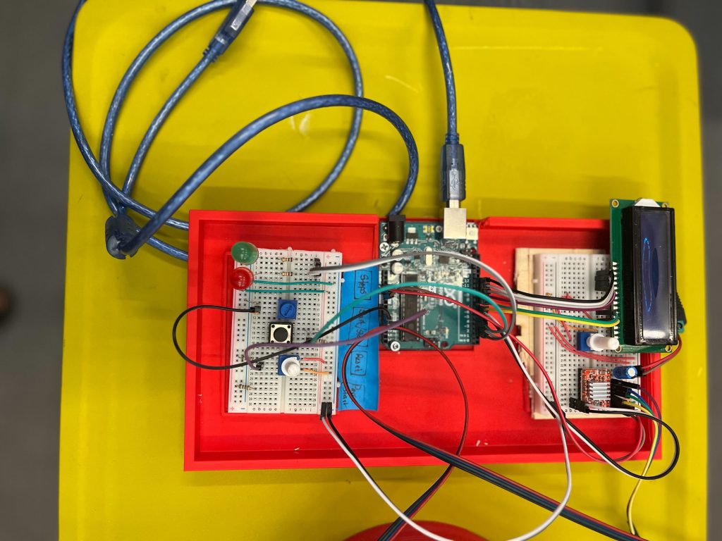
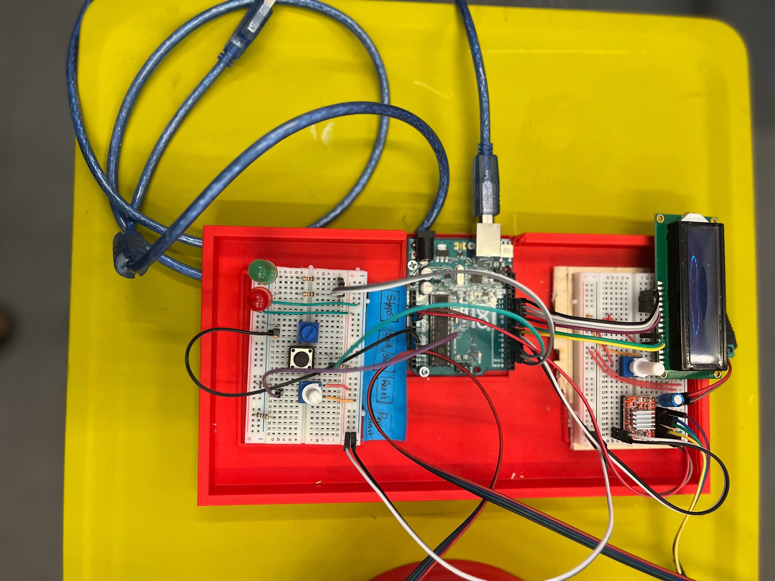
The control board

STL Files

For each part, I’ve created STL files that you can download and print. The files are designed to be printed with common filament materials like PLA or ABS, which offer a good balance between strength and ease of printing. You can download the .stl files from: https://github.com/tashrique/DIY-Turntable-Makerspace-Resources.

  • Base V2: This is the foundation of the turntable. It holds the stepper motor and the bearings.
  • Rotating Platform V2: This part is mounted on top of the bearings and is directly driven by the stepper motor. It is where the object to be scanned is placed.
  • Bearing Holders: These components are used to hold the 608 bearings in place. Print 3 pieces of these.

3D Printing Instructions

  • Material: PLA, PETG, ABS, or ASA
  • Layer Height: 0.2 mm for a good balance of speed and detail.
  • Infill: 15% is sufficient for structural integrity but can be increased for parts under more stress, like the motor mount and gear set.
  • Supports: All parts should print well without supports.
  • Bed Adhesion: Use a raft or brim if you experience issues with bed adhesion during printing.

Assembly Tips

Once the parts are printed, follow these tips for assembly:

  • Before the final assembly, test fit all parts together. This helps identify any print errors or adjustments needed.
  • If some parts don’t fit perfectly, you may need to sand or trim them slightly.
  • Use appropriate screws and adhesive to secure the parts firmly. This ensures the turntable remains stable during operation.
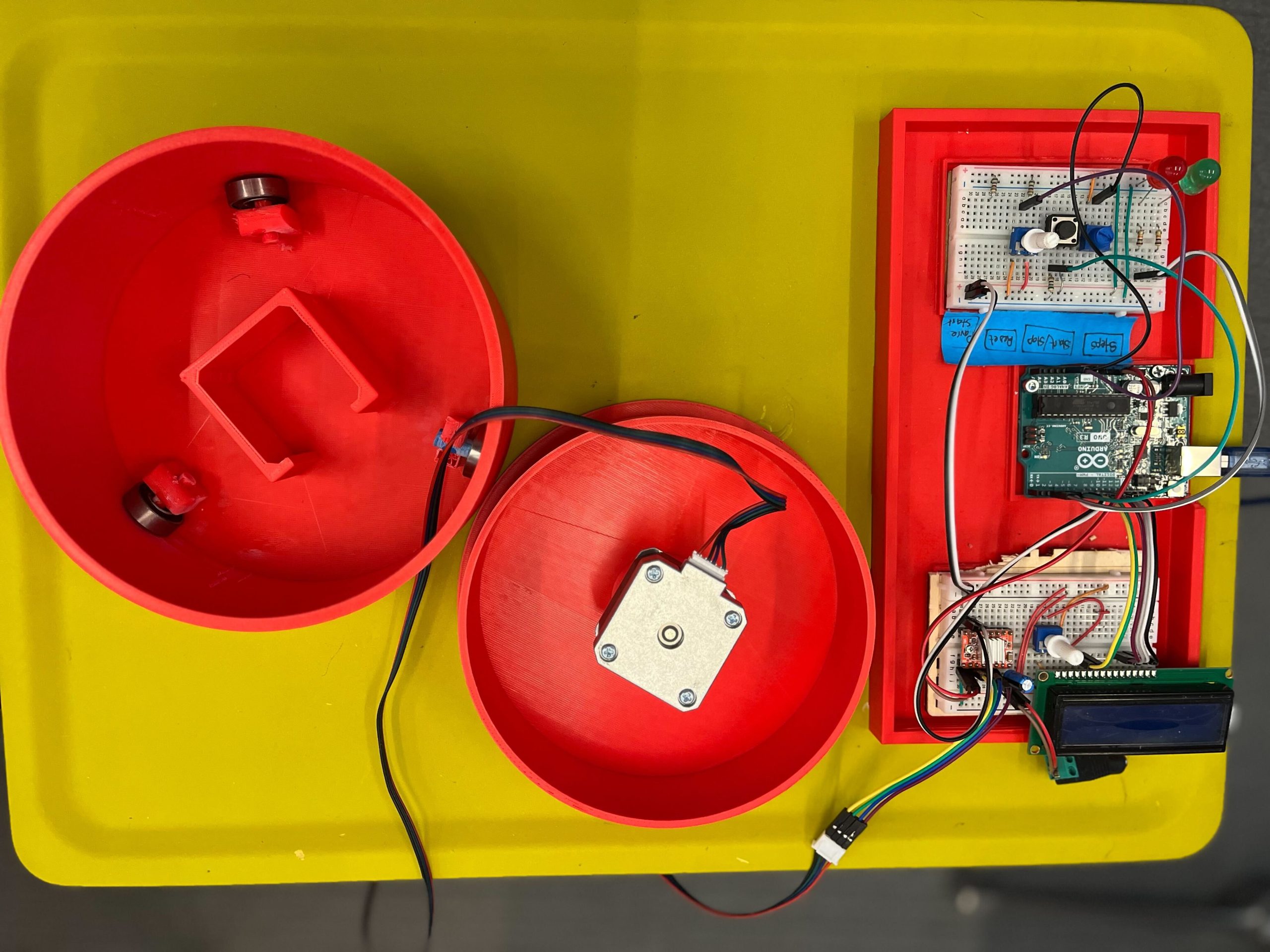
Completed assembly of the turntable

Assembly Process

Assembly Process for the Non-Electronic Components

Tools and Materials Needed

  • Super Glue (optional, for additional stability)
  • Sand Paper (optional, to make edges smooth)

Step 1: Preparing the Base Plate

  • Start by preparing the base plate, clear the base plate of any excess material from printing.

Step 2: Installing the Motor

  • Align the motor mount with the designated area on the base plate.
  • Slide the motor into the slot
  • Ensure the motor shaft protrudes through the mount to align with the gear system.

Step 3: Setting Up Bearings

Objective: Install the bearings that will support the rotating platform.

  • Position the bearing holders on the base plate as per the design.
  • Insert the 608 bearings into the holders. If the fit is tight, you may gently tap them into place using a rubber mallet. You might also want to use superglue to secure the holders in place.
  • Ensure the bearings spin freely without obstruction.

Step 4: Installing the Rotating Platform and Connecting the motor

  • Carefully align the rotating platform with the top of the bearings.
  • Slide and apply moderate pressure to put the motor shaft in the connector until it is stable and level.
  • Check that it rotates smoothly without catching or excessive play.

Step 5: Final Adjustments and Testing

  • Manually rotate the platform to check for smooth motion and correct gear alignment.
  • Make any necessary adjustments to the tightness of screws or alignment of gears.
  • Optionally, apply a small amount of lubricant to the gears and bearings for smoother operation.
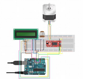
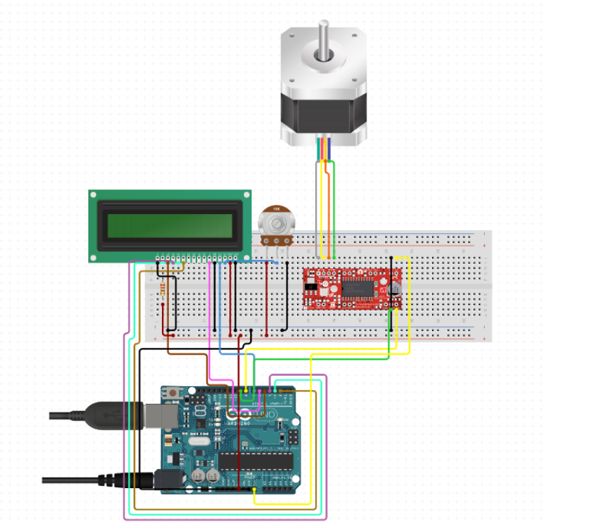
Schematic diagram of the electronic components and pin connections

Electronic Assembly Guide

Tools and Materials Needed

  • Wire Cutters
  • Wire Strippers
  • Soldering Iron (optional, for a more permanent setup)
  • Multimeter (for checking connections)

Step 1: Setting Up the Arduino
Objective: Prepare the Arduino board for connection.

  • Place the Arduino on your workbench or mount it on the base plate.
  • Ensure that it is accessible for connections to both power and other components like the LCD and stepper motor driver.

Step 2: Connecting the Stepper Motor Driver
Objective: Install the A4988 stepper motor driver (Tip: stepper driver documentation).

  • Connect the motor driver to the Arduino using male-to-female jumper wires. Here’s a basic pin connection guide:
  • Connect the DIR (Direction) pin on the driver to a chosen digital pin on the Arduino (e.g., D2).
  • Connect the STEP pin on the driver to another digital pin on the Arduino (e.g., D3).
  • Ensure ENABLE pin is connected if your driver requires it, otherwise it can be left unconnected or tied to ground.
  • Connect the VDD on the A4988 to the Arduino’s 5V output, and GND to one of the Arduino’s ground pins.

Step 3: Wiring the Stepper Motor
Objective: Connect the NEMA 17 stepper motor to the A4988 driver (Tip: NEMA17 documentation).

  • Identify the wire pairs of the stepper motor using a multimeter or by referring to the motor’s datasheet.
  • Connect these wires to the respective A and B terminals on the motor driver. Ensure that the polarity matches the driver’s requirements.
  • Double-check the connections to prevent any potential damage due to incorrect wiring.

Step 4: Adding the LCD Display
Objective: Connect the 16×2 LCD to the Arduino to display status and control messages.

  • Use a breadboard or direct jumper wires to connect the LCD. Typical connections are:
  • RS (register select) to a digital pin (e.g., D4).
  • E (enable) to another digital pin (e.g., D5).
  • D4 to D7 data pins of the LCD to digital pins D6, D7, D8, D9 on the Arduino.
  • Connect the VSS pin of the LCD to the ground and VDD to 5V on the Arduino.
  • Connect a potentiometer to the VO (contrast adjust) pin for contrast control.

Step 5: Power Supply Connection
Objective: Ensure proper power supply connections.

  • Connect the 12V adapter to the VMOT and GND on the stepper motor driver to power the stepper motor.
  • Ensure the Arduino is powered either via USB or an external 9V adapter connected to the VIN pin.

Step 6: Testing and Debugging
Objective: Test the setup to ensure everything is working as expected.

  • Upload a simple test sketch to the Arduino to check motor movements and LCD functionality.
  • Adjust the potentiometer to get a clear display on the LCD.
  • Use the multimeter to troubleshoot any connectivity issues.

Step 7: Final Setup
Objective: Secure all electronic components and clean up the wiring.

  • Use zip ties or cable management clips to organize and secure wires.
  • Ensure all connections are stable and that there’s no risk of loose wires interfering with the moving parts.

Wiring Diagram

LCD Pin Mapping
Reset = 7;
Enable = 8;
D4 = 9;
D5 = 10;
D6 = 11;
D7 = 12;

Stepper Motor Pin Mapping
Step = 6
Direction = 5
(Type of driver: with 2 pins, STEP, DIR)

Programming the Turntable

#include <LiquidCrystal.h>
#include <AccelStepper.h>

void(* resetFunc) (void) = 0;

/*
LCD Pin Map
Reset = 7;
Enable = 8;
D4 = 9;
D5 = 10;
D6 = 11;
D7 = 12;

Stepper PIN Map
Step = 6
Direction = 5
(Type of driver: with 2 pins, STEP, DIR)

*/


AccelStepper stepper(1, 6, 5);

const int rs = 7, en = 8, d4 = 9, d5 = 10, d6 = 11, d7 = 12;
LiquidCrystal lcd(rs, en, d4, d5, d6, d7);

int green = 2;
int red = 3;
int button = 4;
int controls = A1;
int speeds = A0;


String currentStat = "Reset";
String prevStat = "Reset";
int stepsTaken = 0;
bool buttonPressed = false;
bool actionTaken = false;
int buttonClicked = 0;
int currentSpeed = 0;


void setup() {
lcd.begin(16, 2);
pinMode(green, OUTPUT);
pinMode(red, OUTPUT);
pinMode(button, INPUT);

resetControls();
}


void loop() {
runProgram();
}

void runProgram() {
currentSpeed = readSpeed();
currentStat = getStatus();
buttonClicked = buttonClick();

digitalWrite(red, HIGH);

lcd.setCursor(0, 0);
lcd.print(": " + currentStat);

lcd.setCursor(8, 0);
lcd.print("-> " + String(currentSpeed) + "ms");


if (buttonClicked == 1) {
lcd.clear();

//Reset
if (currentStat == "Reset") {
lcd.setCursor(0, 0);
lcd.print("RESETTING...");
stepsTaken = 0;
prevStat = currentStat;
digitalWrite(green, LOW);
digitalWrite(red, HIGH);
resetFunc();
}

//Resume
else if (currentStat == "Start" && prevStat == "Pause") {
lcd.setCursor(0, 1);
lcd.print("RESUMED @" + String(currentSpeed));
prevStat = currentStat;
stepsTaken = commandStart(currentSpeed, stepsTaken);
}


//Start
else if (currentStat == "Start") {
lcd.setCursor(0, 1);
lcd.print("STARTED @" + String(currentSpeed));
prevStat = currentStat;
stepsTaken = commandStart(currentSpeed, 0);
}

else if (currentStat == "Pause" && prevStat == "Pause") {
lcd.setCursor(0, 1);
lcd.print("Already Paused");
}

//Undefined
else {
lcd.setCursor(0, 1);
lcd.print("Invalid Command");
}
}
}


/*--------------------------------------*/

int commandStart(int currentSpeed, int initial) {

lcd.clear();
int steps = 0;

digitalWrite(red, LOW);
digitalWrite(green, HIGH);

for (int i = initial; i <= 200; i++) {
stepper.moveTo(i);
stepper.runToPosition();
lcd.setCursor(0, 1);
lcd.print(i);

lcd.setCursor(4, 1);
lcd.print("/ 200 steps");
steps = i;
delay(currentSpeed);


//Check if any other button is pressed while started
String check = getStatus();
lcd.setCursor(0, 0);
lcd.print(check);

int clicked = buttonClick();
String clickedIndicator = clicked ? "*" : "";
lcd.setCursor(6, 0);
lcd.print(clickedIndicator);

if (clicked) {
if (check == "Reset") {
lcd.clear();
lcd.setCursor(0, 0);
lcd.print("RESETTING...");
delay(200);
stepsTaken = 0;
prevStat = "Reset";

digitalWrite(green, LOW);
digitalWrite(red, HIGH);

resetFunc();
}

else if (check == "Pause") {
lcd.clear();
lcd.setCursor(0, 0);
lcd.print("Paused");
delay(200);
prevStat = "Pause";

digitalWrite(green, HIGH);
digitalWrite(red, HIGH);
return steps;
}
}
}

return steps;
}

/*--------------------------------------*/

int buttonClick()
{
int reading = digitalRead(button);
return reading;
}


void resetControls() {
lcd.clear();
lcd.setCursor(0, 0);
lcd.print("Turntable - Tash!");
digitalWrite(red, HIGH);
digitalWrite(green, HIGH);
delay(500);
digitalWrite(red, LOW);
digitalWrite(green, LOW);
delay(500);
digitalWrite(red, HIGH);
digitalWrite(green, HIGH);
delay(500);
digitalWrite(red, LOW);
digitalWrite(green, LOW);
lcd.clear();
}


String getStatus() {
int controlStatus = analogRead(controls);
int controlRange = map(controlStatus, 0, 1023, 1, 4);
String stat = "";

if (controlRange == 1)
stat = "Reset";

else if (controlRange == 2)
stat = "Pause";

else if (controlRange == 3 || controlRange == 4)
stat = "Start";

else
stat = "-----" ;
delay(100);

return stat;
}


int readSpeed() {
int sensorVal = analogRead(speeds);
int stepSpeed = map(sensorVal, 0, 1023, 250, 5000);
return stepSpeed;
}

The code for the turntable is structured to handle various functionalities: controlling the motor, updating the LCD display, and reading inputs from the rotary encoder. Access the full commented code my GitHub repository: https://github.com/tashrique/DIY-Turntable-Makerspace-Resources

Troubleshooting Common Issues

Motor Noise or Vibration

  • Check alignment of gears and ensure the stepper driver is correctly calibrated.

LCD Display Issues

  • Verify wiring connections and contrast settings; adjust the potentiometer if used or calibrate the voltage divider correctly for clear visibility.

Code Bugs

  • Use serial debugging to monitor outputs and verify that the logic in your sketches matches the intended functions.

Future Enhancements

Integration of IR Sensors

  • Automate the camera shutter operation in sync with the turntable’s rotation to facilitate overnight operations.

PCB Board

  • Integrate all the circuit in a PCB Board

Conclusion

If you have read this far, thank you and good luck! This guide aims to equip you with all the knowledge needed to create and customize your own turntable, fostering further exploration into the fascinating world of DIY electronics. Feel free to share your project progress and reach out with questions or suggestions. Your feedback helps improve and inspire future projects!

 

Lions at the Spruces

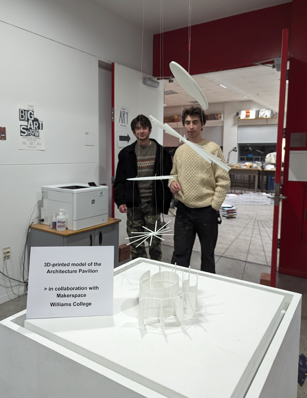
2024 Big Art Show Exhibition

2024 Big Art Show Exhibition

What do Vienna, a long-lost trailer park in Williamstown, and two fifth graders have in common? They all came together via architecture, storytelling, and a whole lot of glue in a Makerspace project that began as a college classroom assignment and grew into something far more textured (literally and metaphorically).

Welcome to ARTS 222 / ENVI 202: Critical Architecture Practice, where theory meets practice, and memory is not only something you hold onto, but something you build.

The Backstory: Lions, Memory, and the Spruces

The Spruces was a trailer park in Williamstown, Massachusetts that was flooded by Hurricane Irene, and then closed in 2016. While it’s no longer standing, its memory continues to ripple through the town’s environmental and architectural narratives. For this class project, led by Giuseppina Forte, Assistant Professor of Architecture and Environmental Studies, (with TAs Elijah Washington ‘24 and Grace Espinosa ’26), students set out to reimagine the site and its emotional geography through architectural modeling.

David Keiser-Clark took measurements of the lion statues (on site) at the former Spruces in Williamstown, MA

David Keiser-Clark took measurements of the lion statues (on site) at the former Spruces in Williamstown, MA

The mission

Recreate a tabletop model of the Spruces site and anchor it with two majestic lions, inspired by those that once guarded the entrance. But these weren’t just any lions.

How to (Re)Build a Lion

Let’s rewind to Vienna, Austria. A statue stands outside the METAstadt in Donaustadt of a proud, regal lion. David Keiser-Clark, Makerspace Program Manager, searched Google and found what appeared to be an exact match of “our” lions at the METAstadt. He found a digital version of the statue that had been uploaded by a tourist who scanned it with Polycam in LiDAR mode with their iPhone 14 Pro Max (credit to @Stefan_80888). David drove to the Williamstown lion statues, and used a 30’ measuring tape to mark down the dimensions.

Left: Autodesk Fusion 360 CAD renderings created by Alice Sore '27, from measurements, to 3D print the pillars and base. Right: digitized lion scan placed, to scale, on top of pillars structure.

Left: Autodesk Fusion 360 CAD renderings created by Alice Sore ’27, from measurements, to 3D print the pillars and base. Right: digitized lion scan placed, to scale, on top of pillars structure.

Alice Sore ’27, a Makerspace student worker, used AutoDesk’s Fusion 360 software to model the statue’s pedestals and columns from scratch, creating not just pieces of the project but a learning moment. She used this experience to then lead the Makerspace’s first “Teach-In: Learning Fusion 360”, and walked fellow students through the software and showed them how to model architectural structures with precision and confidence.

Intelligent CAD modeling includes auto-centering devices that also add strength and rigidity.

Intelligent CAD modeling includes auto-centering devices that also add strength and rigidity.

Once the lion, pedestal, and columns were ready, we printed them in white PLA in four separate sections, kind of like Legos for architects, and bonded them with cyanoacrylate glue.

Left: first completed statue. Right: The second one is always easier and quicker.

Left: first completed statue. Right: The second one is always easier and quicker.

But they weren’t finished. Not yet.

Enter: Two Fifth Graders and a Can of Paint

What do you do when you want your lion statues to look like they’ve stood in the elements for decades, rather than hours?

You recruit two fifth graders, naturally.

Elizabeth Heeringa and Anderson Keiser-Clark, fifth graders, provided the vision for aging and the labor to complete the entire post-processing effect. (Clockwise from top left: Anderson on left, and Elizabeth on right; Elizabeth dry brushing with greens to create moss effect; Bottom left: more dry bushing; Bottom right: Getting out the ladder as these lions are tall!

Elizabeth Heeringa and Anderson Keiser-Clark, fifth graders, provided the vision for aging and the labor to complete the entire post-processing effect. (Clockwise from top left: Anderson on left, and Elizabeth on right; Elizabeth dry brushing with greens to create moss effect; Bottom left: more dry bushing; Bottom right: Getting out the ladder as these lions are tall!
Elizabeth Heeringa and Anderson Keiser-Clark, armed with brushes, DryLok Masonry Waterproofer, acrylic paint, a misting bottle, and a creative eye, transformed glossy 3D prints into textured, time-worn sentinels. They painted the lions with two coats of DryLok, which added grit (sand is in the paint) and also obscured the 3D printed lines. They then used an “acrylic wash”, a mixture of 85% water and 15% black acrylic paint, and spritzed the lions multiple times, allowing them to dry between each coating. Finally, they used a technique called dry-brushing, using tiny brushes and miniscule amounts of pure acrylic color to create highlights. They used greys to emphasize age, and greens to simulate moss or lichen, until the lions no longer looked like something made yesterday but like artifacts pulled from a lost world. (Elizabeth shared that an optional final step would be to dip a paint brush in white acrylic paint and then flick it at the object to create little stippled drops of paint.)

Elizabeth initially warned that the black acrylic wash solution goes on strong and creates deep and dark puddles, but eventually dries much lighter. Effectively, she said: "Don't worry, David." Left: You can see the difference of the acrylic wash on cardboard (dried dark), and how 3 successive additive layers dried on the scrap base with slightly darker tones and increase variation of patterning. Right: Massive puddling and dripping of black paint that will dry in significantly lighter tones.

Elizabeth initially warned that the black acrylic wash solution goes on strong and creates deep and dark puddles, but eventually dries much lighter. Effectively, she said: “Don’t worry, David.” Left: You can see the difference of the acrylic wash on cardboard (dried dark), and how 3 successive additive layers dried on the scrap base with slightly darker tones and increase variation of patterning. Right: Massive puddling and dripping of black paint that will dry in significantly lighter tones.

Elizabeth created this original 3D post processing recipe from scratch. You saw it here first.

Anderson also helped calibrate the Makerspaces 3D printers, because of course he did.

Left: Lion dripping from the acrylic wash spray; Right: Completed lion after multiple acrylic wash sprayings.

Left: Lion dripping from the acrylic wash spray; Right: Completed lion after multiple acrylic wash sprayings.

A Model of Memory

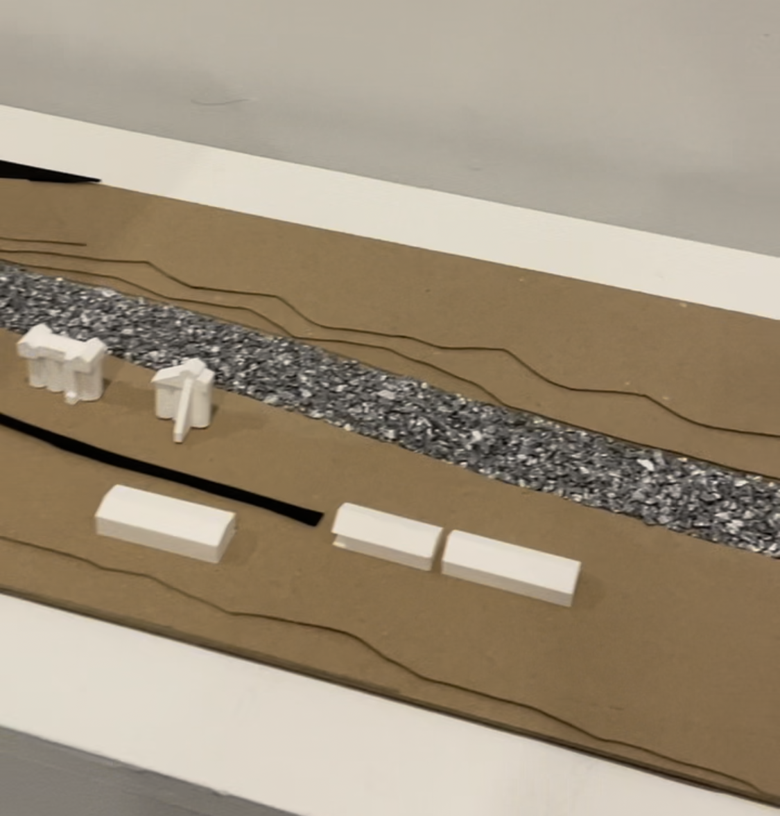
Meanwhile, Professor Forte and her team worked on designing the 30” x 30” tabletop model of the Spruces site built to a scale of 800:1, which means it represents a 2,000’ x 2,000’ section of land. Four interlocking 15” x 15” environmentally friendly MDF panels called Eucaboard (made from eucalyptus fibers), two layers thick, formed the base. An etched river flows through the landscape, marked by laser-etched topography and filled with translucent blue acrylic.

Every detail of mobile homes represented by tiny markers, zones carved into MDF, and even the idea of including a scale model trailer with furnishings was designed to be both informative and deeply effective. This wasn’t just about land use. It was about memory, displacement, community, and presence.

Why It Matters

Architecture isn’t just about buildings. It’s about what we build to remember. What we build to mean something.

This project took a long-forgotten corner of Williamstown, wrapped it in theory, scaled it to human imagination, and rebuilt it with resin, MDF, paint, and story.

It involved artists, scientists, young makers, international scans, and kids with paintbrushes.

And as the lions stood silent, strong, slightly green at the mane you could almost hear them guarding the gates not just of a trailer park, but of a memory that refuses to fade.

Left: Lion and Elizabeth; Right Anderson and Lion.

Left: Lion and Elizabeth; Right Anderson and Lion.

2024 Spring Big Art Show Exhibition. Lions standing as sentinels.

2024 Spring Big Art Show Exhibition. Lions standing as sentinels.

Elizabeth’s Post Processing Recipe

Elizabeth mentions it’s important to use the normal version of DryLok Masonry Waterproofer, as the “extreme” version lacks the sandy texture.

Elizabeth's supplies.

Elizabeth’s supplies.

More Information

Postscript (February 14, 2025)

Brenda Aubin of Dining Services reached out to the Makerspace to include the lions in their Winter Carnival celebrations, complete with AV and slideshows for ambience. Dining Services rock!

Brenda Aubin of Dining Services reached out to the Makerspace to include the lions in their Winter Carnival celebrations, complete with AV and slideshows for ambience. Dining Services rock!

Sustainable 3D Printing at Williams College (Part 2)

Polyformer Updates

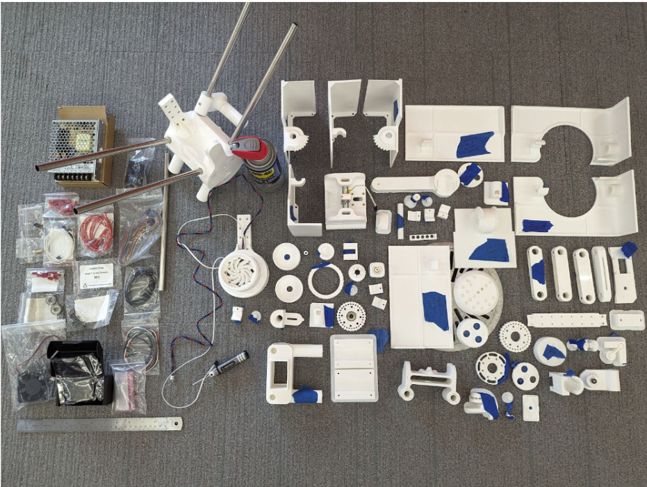
Polyformer 3D printed parts and electronics ready to be assembled.

Polyformer 3D printed parts and electronics ready to be assembled.

My name is Camily Hidalgo Goncalves, and I am a sophomore at Williams College majoring in Chemistry with a Neuroscience concentration. As a Makerspace student worker, I have recruited Milton Vento ’26, Tashrique Ahmed ’26 (both Computer Science students at Williams College and fellow Makerspace student workers), and Oscar Caino ’27, a student at Swarthmore College who is a prospective Engineering major, to assist me in assembling the Polyformer parts and electronics. We have completed several milestones, and made significant progress on the Polyformer project at Williams College. This innovative project aims to upcycle waste plastic bottles into locally-sourced 3D printer filament.

Assembly and Integration

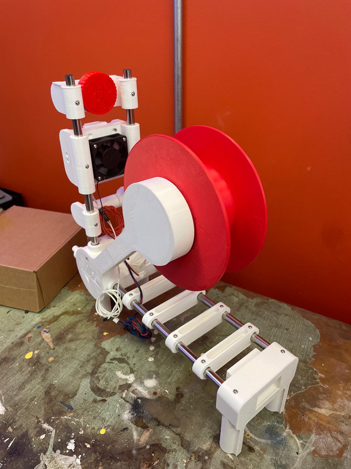
The assembled Polyformer

The assembled Polyformer

Milton, Oscar and I worked together to assemble the 78 individual 3D-printed parts required for the Polyformer. This intricate process demanded precision and teamwork. Following the assembly of the physical components, I assisted Tashrique with integrating the electronics. This included the installation of a circuit board, LCD screen, volcano heater block, stepper motor, and various sensors and wiring. These components are essential for the Polyformer to function effectively, converting plastic bottles into usable 3D printer filament. 

Collection and Processing of Plastic Bottles

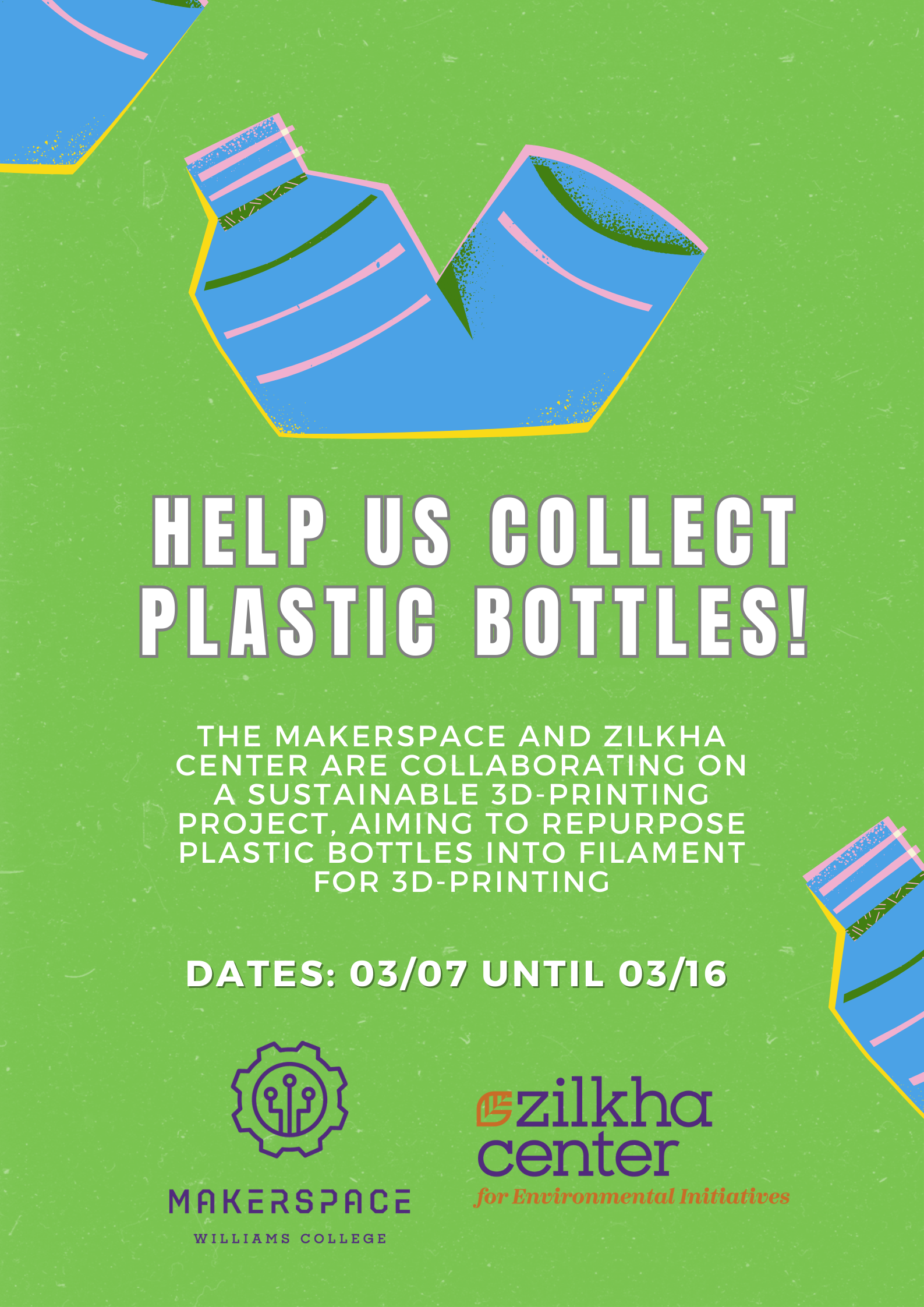
Plastic bottle collection poster.

Plastic bottle collection poster.

In preparation for testing, we collected approximately 75 plastic bottles. These bottles were contributed by the Williams College community, demonstrating a collective effort to reduce plastic waste. Elena Sore ‘27, a prospective Computer Science major and Makerspace student worker, and I worked on the initial step in the processing phase, which involved us cleaning the bottles and cutting them into long, consistent ribbons. These plastic ribbons will then be fed into the Polyformer, where they will be melted and extruded into filament.


Testing and Quality Assurance

Next fall semester we will begin rigorous testing to ensure that the Polyformer operates smoothly and produces high-quality filament that meets the required standards for 3D printing. Several tests will be conducted, including:

  1. Durability Testing: Assessing the strength and flexibility of the produced filament.
  2. Consistency Testing: Ensuring the filament has a uniform diameter, which is crucial for reliable 3D printing.
  3. Compatibility Testing: Verifying that the filament performs well with various 3D printers and printing conditions, while accommodating different material thicknesses from various brands of PET bottles.

Project Goals and Benefits

The Polyformer project aligns with Williams College’s sustainability goals and offers numerous benefits:

  • Waste Reduction: By upcycling plastic bottles, we reduce the amount of plastic waste that ends up in landfills or oceans.
  • Sustainability Education: The project serves as a hands-on educational tool, teaching students about the importance of repurposing and innovative ways to repurpose waste materials.
  • Local Impact: The filament produced will be used to create practical items such as plant pots and compost bins for the Zilkha Center for Environmental Initiatives, supporting local sustainability efforts.

Next Steps

We hope to create a sustainable cycle of converting plastic waste into useful products, while minimizing the environmental impact of plastic disposal. This project provides practical solutions to plastic waste,  and also serves as an educational tool, raising awareness about sustainability and encouraging innovative thinking in environmental conservation.

As we move forward, our next steps will be to refine the process and increase the efficiency of the Polyformer:

  1. Rigorous Testing: Thoroughly test the Polyformer to ensure it produces reliable and high-quality filament that meets 3D printing standards.
  2. Scaling Up: Increase the number of collected bottles and the quantity of filament produced.
  3. Educational Workshops: Host campus workshops to educate the broader community about the Polyformer and the importance of sustainable practices. We might seek to collaborate with the Williamstown Milne Library to host a workshop for local community members.
  4. Research and Development: Continue to improve the design and functionality of the Polyformer based on feedback and test results.

Acknowledgements

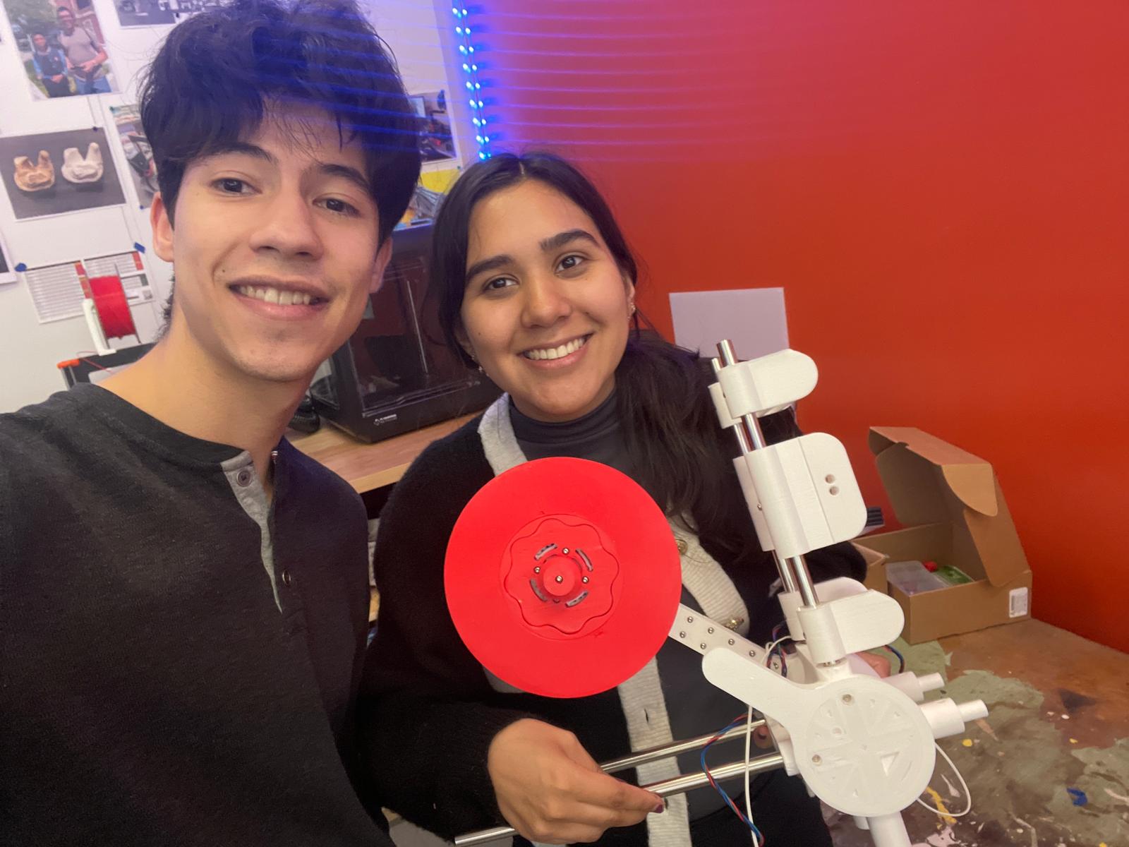
Assembling the Polyformer: Oscar Caino ‘27, a Swarthmore College student (left), and Camily Hidalgo Goncalves ‘26, a Williams College student (right).

Assembling the Polyformer: Oscar Caino ‘27, a Swarthmore College student (left), and Camily Hidalgo Goncalves ‘26, a Williams College student (right).

This project would not have been possible without the ongoing support and collaboration received. We are immensely grateful to our collaborators: David Keiser-Clark (Makerspace Program Manager), Milton Vento ‘26, Tashrique Ahmed ‘26 and Elena Sore ‘27 (Makerspace Student Workers), Yvette Belleau (Lead Custodian, Facilities), Christine Seibert (Sustainability Coordinator, Zilkha Center), Mike Evans (Deputy Director, Zilkha Center for Environmental Initiatives), and Oscar Caino ‘27 (Swarthmore College Student). Their expertise, guidance, and contributions have been invaluable to the progress of the Polyformer project.

Stay tuned for more updates as we continue to develop and test the Polyformer. Together, we can make a significant impact in reducing plastic waste and promoting sustainable practices at Williams College.

Reefs Reimagined: 3D Printing the Effects of Tsunamis on Coral

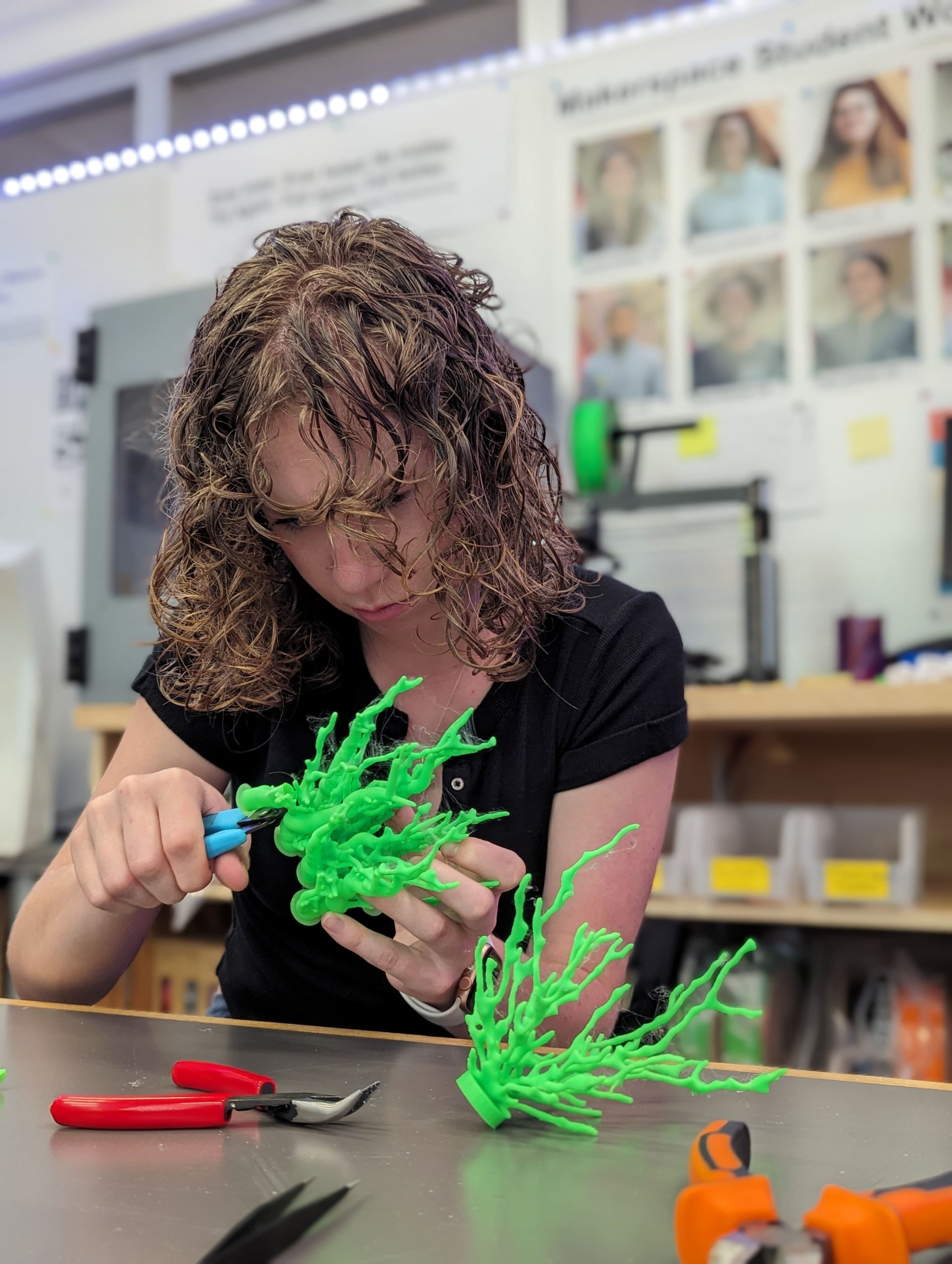
Lauren Mukavitz ‘27: In the Makerspace taking the supports off my finished models

Lauren Mukavitz ‘27: In the Makerspace taking the supports off my finished models

When most people think about coral reef degradation, they often think about bleaching and the effects of climate change. However, coral faces another danger that is hardly talked about—tsunamis. Coral reefs have a unique structure that increases the friction a tsunami encounters on its way to the shore, slowing down the wave and mitigating damage. However, the intense forces during a tsunami can be extremely damaging and can destroy entire reefs. To better understand this impact, I embarked on a project for my class Geologic Hazards with Mike Hudak, Assistant Professor of Geosciences, to model coral before and after a tsunami.


Replicating Tsunami Damaged Coral

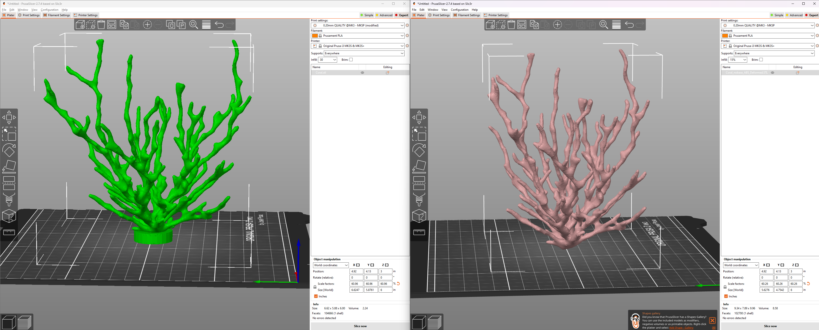
First, I created an undamaged model that represented a small colony of coral polyps before a tsunami event. I used Ultimaker Cura to design a 3D model of the coral. Next, I wanted to simulate the damage caused by a tsunami. After struggling to find existing methods for modeling tsunami forces on coral, I teamed up with the David Keiser-Clark, Makerspace Program Manager, Elena Sore, Makerspace Student Worker, and Jason Mativi, Science Shop Instrumentation Engineer, to use SolidWorks, a 3D CAD program. We applied a nonlinear analysis with 0.3 bar (or 3E3 N/m^2) of pressure, the estimated force an average piece of coral experiences during a tsunami, to the undamaged model and let SolidWorks create a “deformed” model for us. It took the software approximately four hours to render these forces to the 3D model.

Left: Original coral model; Right: Same model but deformed using SolidWorks to simulate tsunami forces

Left: Original coral 3D model; Right: Same model but deformed using SolidWorks to simulate tsunami forces

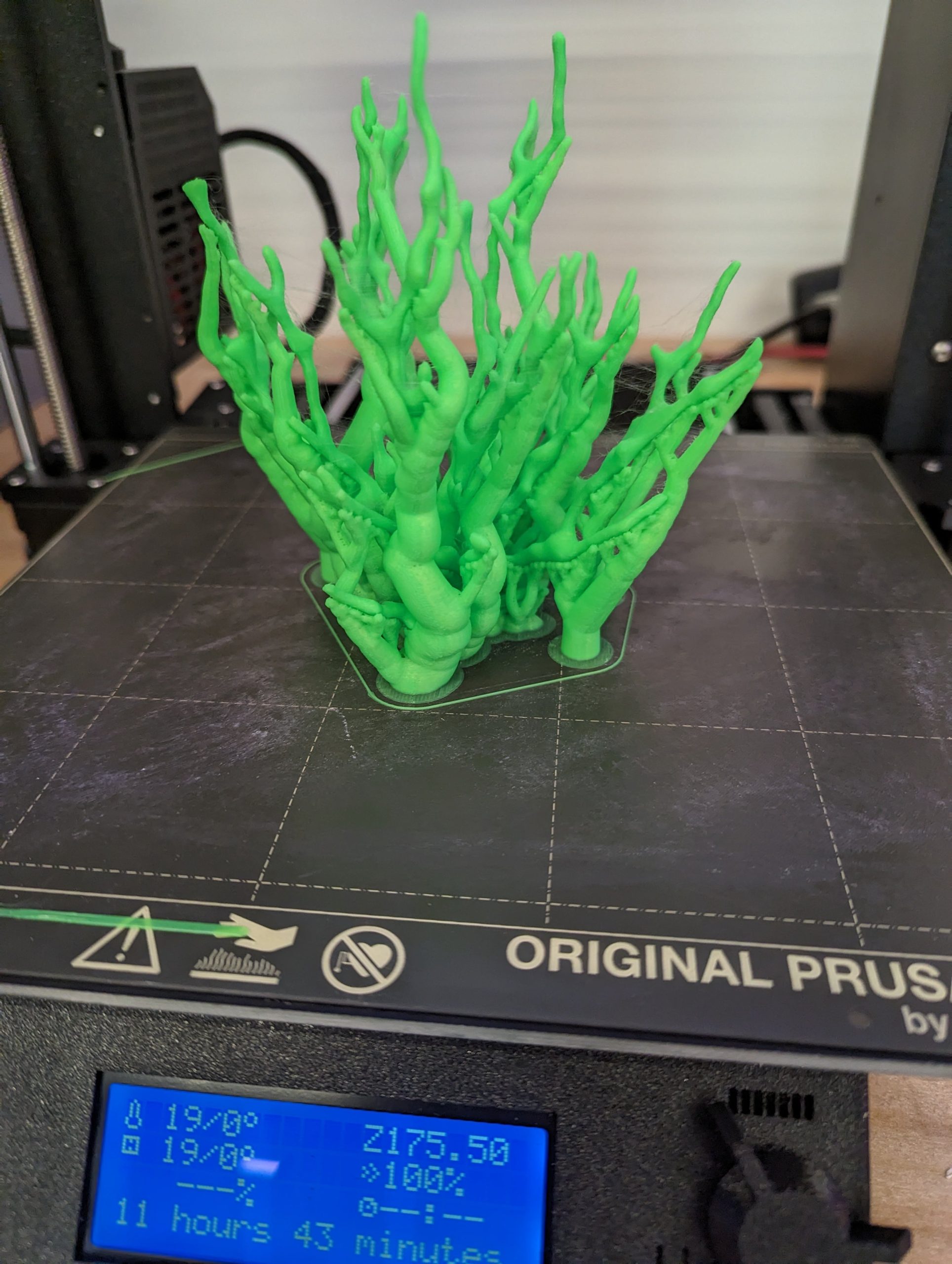
The successful PLA print -- Stonefil was not a fan of my design

The successful PLA print — Stonefil was not a fan of my design

Then I had both models printed at the Makerspace. Initially, we tried using Stonefil PLA, a filament that would approximately mimic coral’s composition with its half PLA (a polyester typically derived from fermented plant starch, such as corn, cassava, sugarcane, or sugar beet pulp) and half ceramic powder. However, the model was too intricate for the material, resulting in a messy and unusable print. We ended up using standard PLA for the final models, which, while less accurate in texture, allowed us to proceed with the physical representation. To simulate sediment damage, I took the “deformed” model to the science shop and used a sandblaster. Unfortunately, the PLA was too strong, and the glass beads in the sandblaster didn’t deform as expected. So, we resorted to breaking the model by hand to represent the kind of physical damage coral might endure during a tsunami.

My models are only approximations of the damage coral sustains during tsunamis. The exact forces on coral polyps during these events are unique and complex, making accurate modeling challenging.

Next Steps

The first step to creating a more accurate model would be refining the methods to determine the necessary forces and coefficients. Then, we could use a 3D CAD program like SolidWorks for a more precise analysis. Additionally, applying post-processing techniques to the 3D printed models, such as using adhesives and texturing materials, could make the PLA models physically look-and-feel more like real coral, enhancing their realism.

Creating more accurate models provides a deeper understanding of the interactions between coral reefs and tsunamis, helping us plan better for these events. This knowledge can guide conservation efforts, inform disaster preparedness strategies, and contribute to the broader field of marine biology. As better models are developed, we move closer to mitigating the devastating impacts of natural disasters on vital ecosystems like coral reefs.

Postscript (August 16, 2024)

See related CNN article: Why this scientist is leaning on surfers, skaters and artists to protect the ocean – “Cliff Kapono is a Native Hawaiian pro surfer and chemist in a race to save the ocean he loves. He co-founded The Mega Lab, a science research group that welcomes anyone (no degree required!) who can help them develop technology and raise awareness about dying coral reefs.”

Postscript (September 9, 2024)

See related CNN article: See the technique that could help save the Great Barrier Reef – “Researchers in Australia are testing a technique called ‘coral seeding’ [that utilizes 3S printers] to help the Great Barrier Reef recover from the effects of climate change.”


The Lincoln Logs: Printing for the WCMA’s Emancipation Exhibition

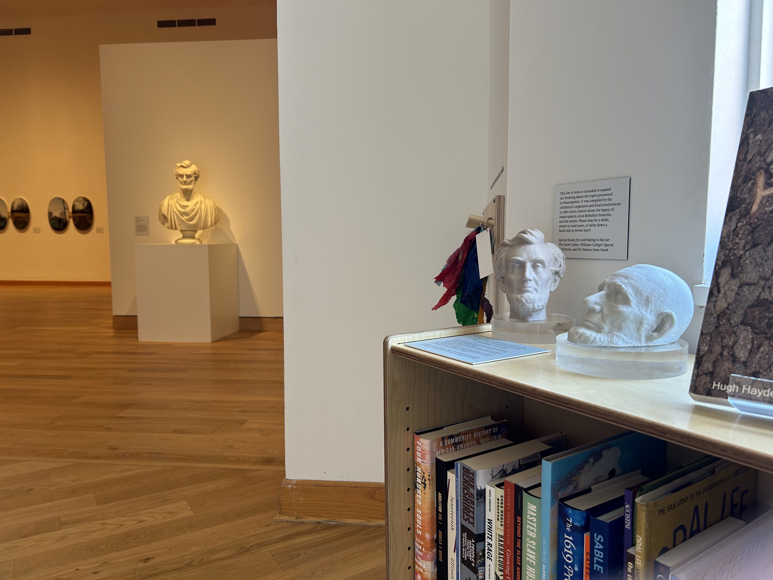
WCMA’s “Emancipation: The Unfinished Project of Liberation” exhibit

“Emancipation” exhibit

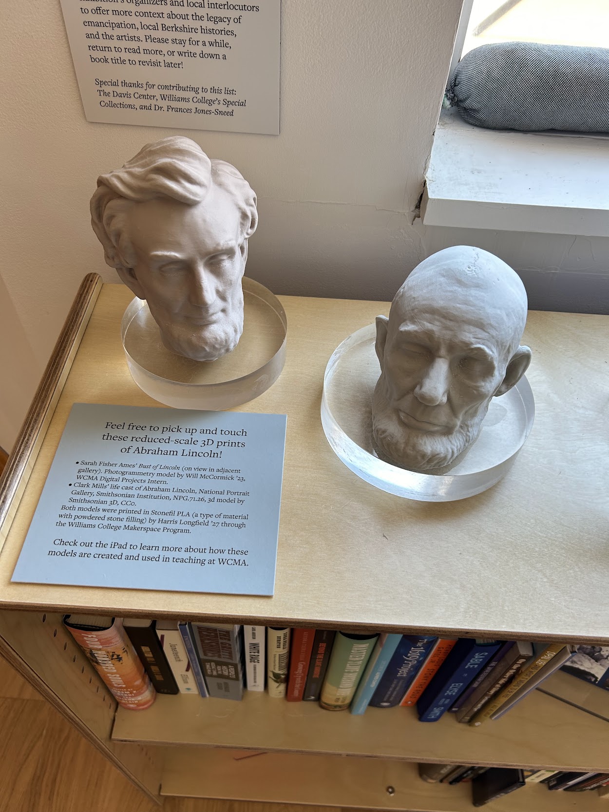
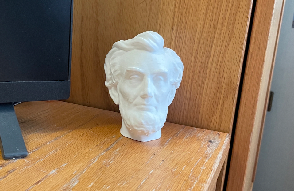
My most recent Makerspace academic project was assisting Beth Fischer, Assistant Curator of Digital Learning and Research for the Williams College Museum of Art. My task was to 3D print replicas of two sculptures of President Lincoln—Sarah Fisher Ames’ bust of Lincoln and the iconic Abraham Lincoln Life Mask by Clark Mill—as part of the WCMA’s “Emancipation: The Unfinished Project of Liberation” exhibits. These two models complement the work of Hugh Hayden, also present at Emancipation, who incorporates PLA prints into his artistic process. The exhibit emphasizes 3D printing as a relatively accessible medium for creativity and showcases different ways it can assist other styles of art, particularly molds.

Setup

The two photogrammetry-based 3D models were gorgeous. They defined every ridge, bump, and strand of hair on Lincoln’s head while carrying the texture of the clay, but it was this beauty that posed a challenge. The multidimensional texture in clay is hard to depict using horizontal layers of filament, which is how 3D printers print. Although not a solution, a remedy to this problem was using a hybrid filament – part ceramic and part PLA. Although this filament can’t recreate the vertical complexity of a sculpted model’s texture, it provides a smoother, heavier finish that better resembles the original material. 

Gallery View of the WCMA Emancipation Exhibition

Gallery View of the WCMA Emancipation Exhibition

We had some leftover StoneFil filament from a previous project, but we knew we would need more to complete both prints. The question was how much more. We did not know how much filament remained on the spools and there was no specific size requested – simply that the two models remain proportional and be as large as possible. 

Naturally, as a math major, I took this as a challenge to maximize the size we could print with only one additional spool of filament. First, I printed two smaller models, noted their xyz scaling, and measured the distance from the nose to the chin. I then used those measurements to find the scale between the height of one and the length of the other. Then, given that scaling, I noted the estimated combined length of the models at a few different sizes and found the factor at which the necessary filament would scale in comparison to the size. In theory, I could approximate the maximum print size given the length of the filament we had left and the spool arriving soon. There was only one problem – we didn’t know how much filament we had. We could weigh the filament, but any statement on the spool-to-filament proportion would’ve been guesswork. 

That was when another Makerspace student worker, Alice Sore, had an idea to create a reference guide for the weight of empty filament spools. We use a variety of brands of filament, and each has a different sized spool. Now, when we finish a spool, we weigh it and enter it into a spreadsheet, allowing us to measure the amount of filament remaining on any given spool by subtracting the spool from the overall weight. 

Printing and Troubleshooting

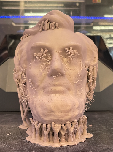
The final bust with its supports still attached

The final bust with its supports still attached

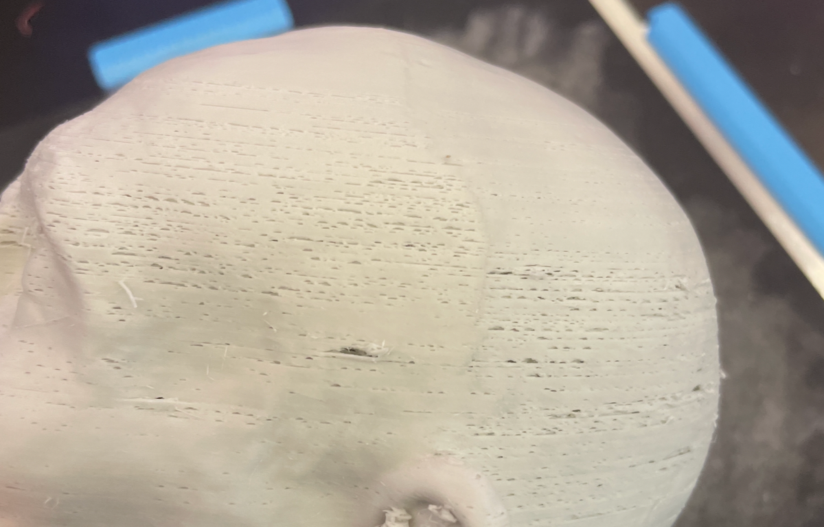
The time came to print the models. I had decided on the heights 140mm and 93.15, which would give us just enough filament to print both models with enough to spare to be able to still print one more, just in case of failure. I sliced and started the print of the bust and 20 hours later, it came out well. There were a few small holes that indicated mild under-extrusion, but they were not too distracting and the WCMA was interested in showcasing the uniqueness of 3-D prints, so I was perfectly content with the model. 

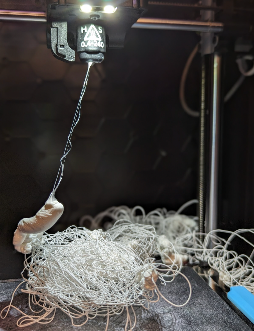
The second print was not as fortunate. Externally, it looked fine, except the under-extrusion was more visible than the first model. Before removing the model from the plate, I started googling remedies for under-extrusion because I was concerned that I didn’t have enough filament to endure another failure. I recalibrated the printer, increased the nozzle temperature, slightly decreased the printing speed, and ran another mini model with ordinary PLA. It came out perfectly – and that worried me because I was nervous that the problem was with the ceramic filament, which was a requirement for the project. Eventually, I stumbled onto a solution by turning the StoneFil model upside down to examine the supports, and to my shock, I found that they were completely “spaghettified”. The supports had completely failed and were just a mess of tangled filament. I was impressed that the print had managed to build at all. 

The under-extrusion was far more noticeable on the first print of the mask than the bust.

The under-extrusion was far more noticeable on the first print of the mask than the bust.

Exhibition: “Feel free to pick up and touch these reduced-scale 3D prints of Abraham Lincoln!”

Exhibition: “Feel free to pick up and touch these reduced-scale 3D prints of Abraham Lincoln!”

I spent some time in different slicing softwares, trying to optimize the supports. It took (admittedly longer than it should have) to realize that with supports as dense as the model requested, this was a rare case where it would be more filament-efficient and less failure-prone to fill the space underneath the mask with infill, instead of supports. This was the solution we went with, and the bust printed perfectly.

While weighing the options for the final print, David Keiser-Clark, Makerspace Program Manager, and I brainstormed ways of filling in the holes caused by under-extrusion. Our favorite idea, and the only experiment we ran, was using a heat gun to melt a tiny bit of StoneFil filament into the hole and then sand down the excess. It was good in theory, and fun to try, but not entirely effective because it looked like a visible patch. This is because 3D printing filament solidifies incredibly fast after cooling, and we would have needed to either pour a liquid into the hold and/or do a tremendous amount of sanding afterward.

Conclusion

Coincidentally, as the final prints started, I again fell very ill and had to return home for the week and did not get to hand off the pieces. However, I did get the chance to go to the Emancipation exhibit and see the final results. The space itself was a moving experience, and I would strongly encourage anybody to visit or read about the exhibition and its incorporation of 3D printing. This was a fun project to complete during Winter Study, and I got the chance to answer a lot of looming questions about 3D printing during it. I learned a lot about the balance of layer height, print speed, and temperature, I’m excited to see what else we can do with our filament data log, and melting PLA with the heat gun was so much fun that I may try to find a way to make it practical. Although, I must admit, my favorite part of this project is the little Lincoln that found himself a home in my dorm.

An early, miniature prototype that now adorns my desk as a reminder of my work on this WCMA project!

An early, miniature prototype that now adorns my desk as a reminder of my work on this WCMA project!

Lost but Found in the Photogrammetry World

The Quandary

Have you ever broken or lost a small part of an important object you value? Perhaps the strap of that beautiful watch you got from your grandma or the battery cover for the back of your remote control? You looked for it everywhere, but the part was too “insignificant” to be sold on its own. Or it just wasn’t the sort of thing that anyone would expect to need a replacement.

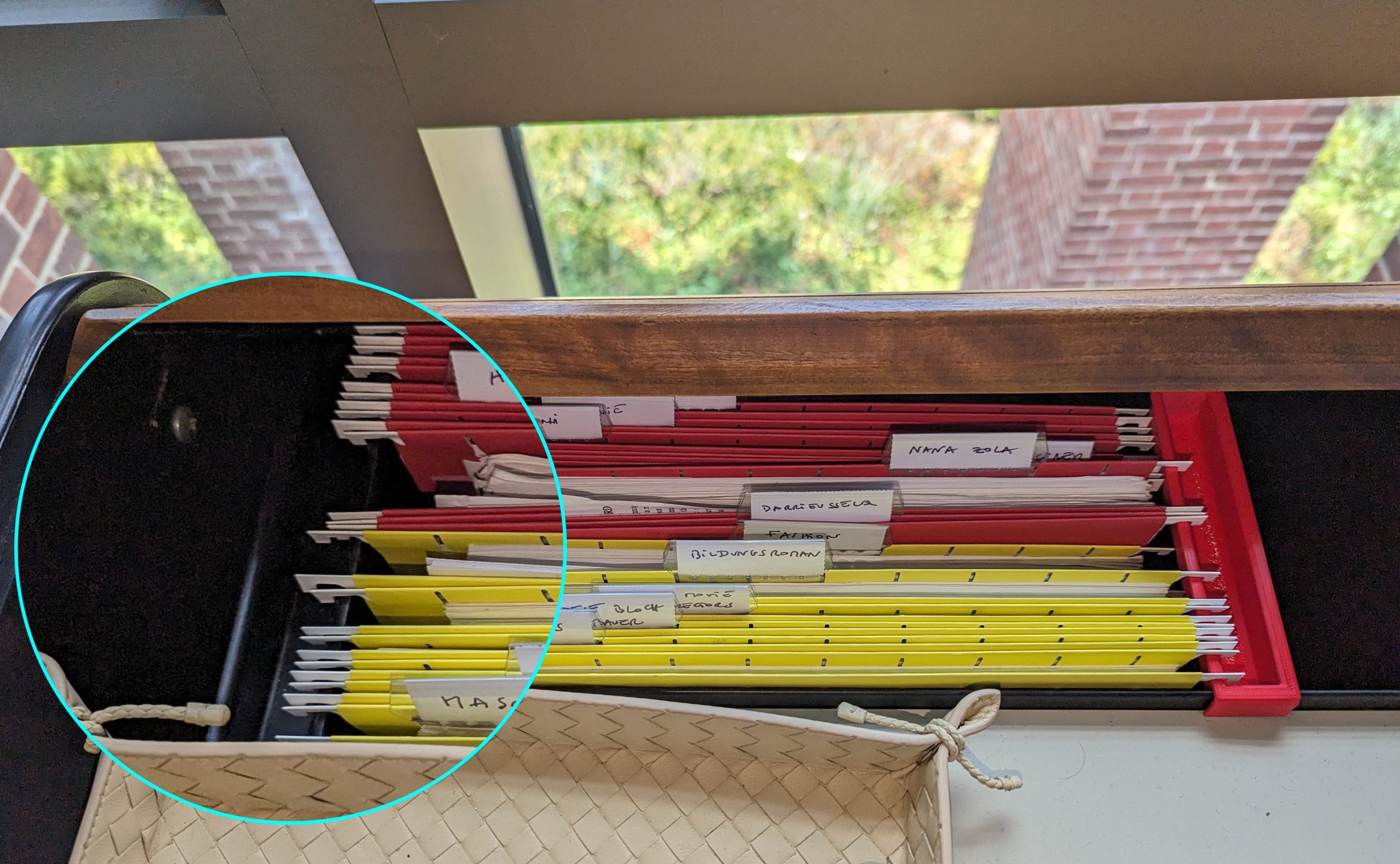
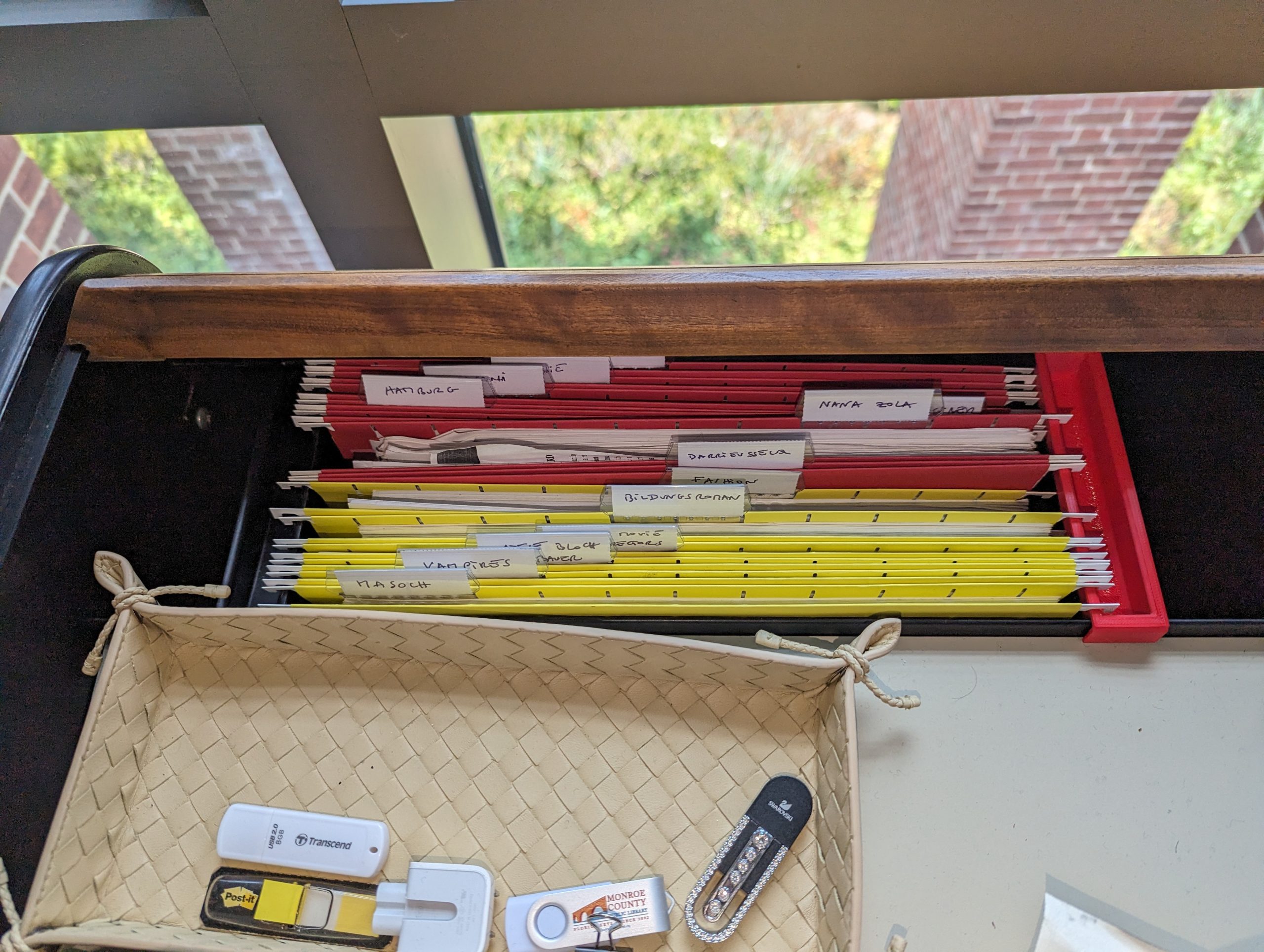
The original black “obsolete plastic object” (on left) keeping files safely stored, alongside the newly cloned red part (on (right)

The original black “obsolete plastic object” (on left) keeping files safely stored, alongside the newly cloned red part (on (right)

Last semester at Williams College, Chris Koné, Associate Professor of German and Director of Oakley Center for Humanities & Social Sciences, had a similar experience. He lost an integral part of his desk that allows him to keep his files neatly stored and organized (shown on picture). Desperate to have a place for the files and papers scattered miserably on the floor, Prof. Koné looked in a brick and mortar NYC office parts store, as well as on Amazon, eBay, and other e-commerce websites, but alas, the object was nowhere to be found. It had become obsolete!

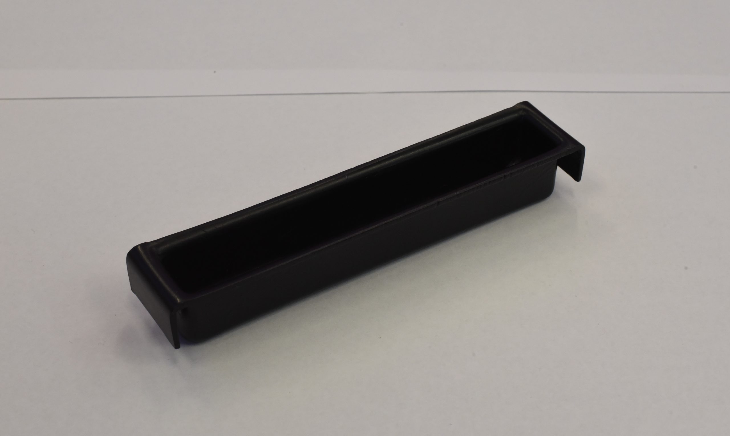
The “obsolete plastic object”

The “obsolete plastic object”

Determined to leave no stone unturned in finding a replacement for the obsolete plastic object, Prof. Koné did what any sensible person with access to the Makerspace would do – he asked for a 3D-printed model of the object! And it is here that he met me, an intern working at the Makerspace over the summer. In the process of helping him, I learned about multiple methods of photogrammetry and created a significantly more efficient and streamlined workflow for the Makerspace. 

Some Background

As a new student worker with zero knowledge about photogrammetry and 3D printing, David Keiser-Clark, the Makerspace Program Manager, thought this project would be just the right amount of challenge for me. Photogrammetry is the process of creating a 3-dimensional digital model of an object by taking dozens or hundreds of photos of the object from different angles and processing them with software to create a digital spatial representation of the object. Doing this project would be a good introduction to the 3D digital world while allowing me to get acquainted with the Makerspace.

If you have tried photogrammetry, you know that some of the most difficult objects to work with are those that are dark or shiny. This object was dark and shiny! When an object is dark, it becomes difficult for the software to distinguish one feature on the object from another, resulting in an inaccurate digital representation. Likewise, light is reflected when an object is shiny, resulting in images that lack details in the shiny areas. Thus, you can imagine how challenging it is when your object is both shiny and dark!

Step 1

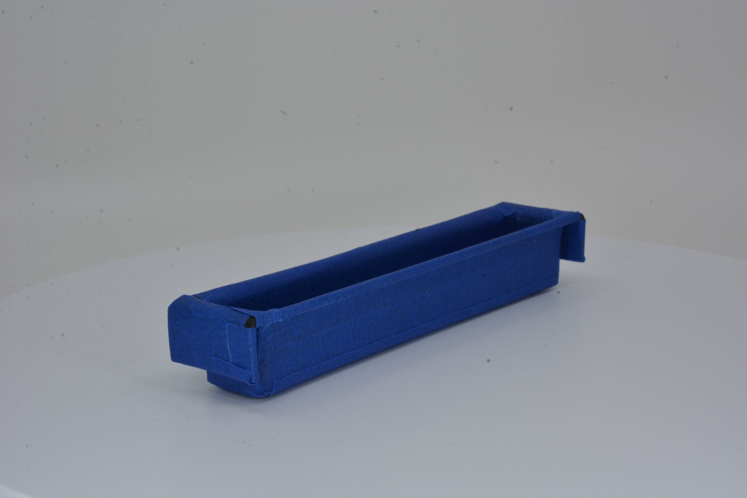
The first step was to figure out how to reduce the darkness and shininess of the object. To kill both birds with one stone, I covered the object with white baby powder, a cheaper alternative to expensive photogrammetry sprays used in industry. The powder’s white color would help eliminate the object’s darkness and offer it some helpful texture, while its anti-reflective nature would reduce shininess. After several attempts to completely cover the object, this method proved ineffective as the powder would not stick to the object’s smooth surface. A little out-of-the-box thinking led me to cover the object with matte blue paper tape, which proved very effective as the tape’s rough texture allowed minimum light reflection. 

obsolete plastic object coated with blue tape

obsolete plastic object coated with blue tape

A Bit of Photography

Milton taking pictures for photogrammetry

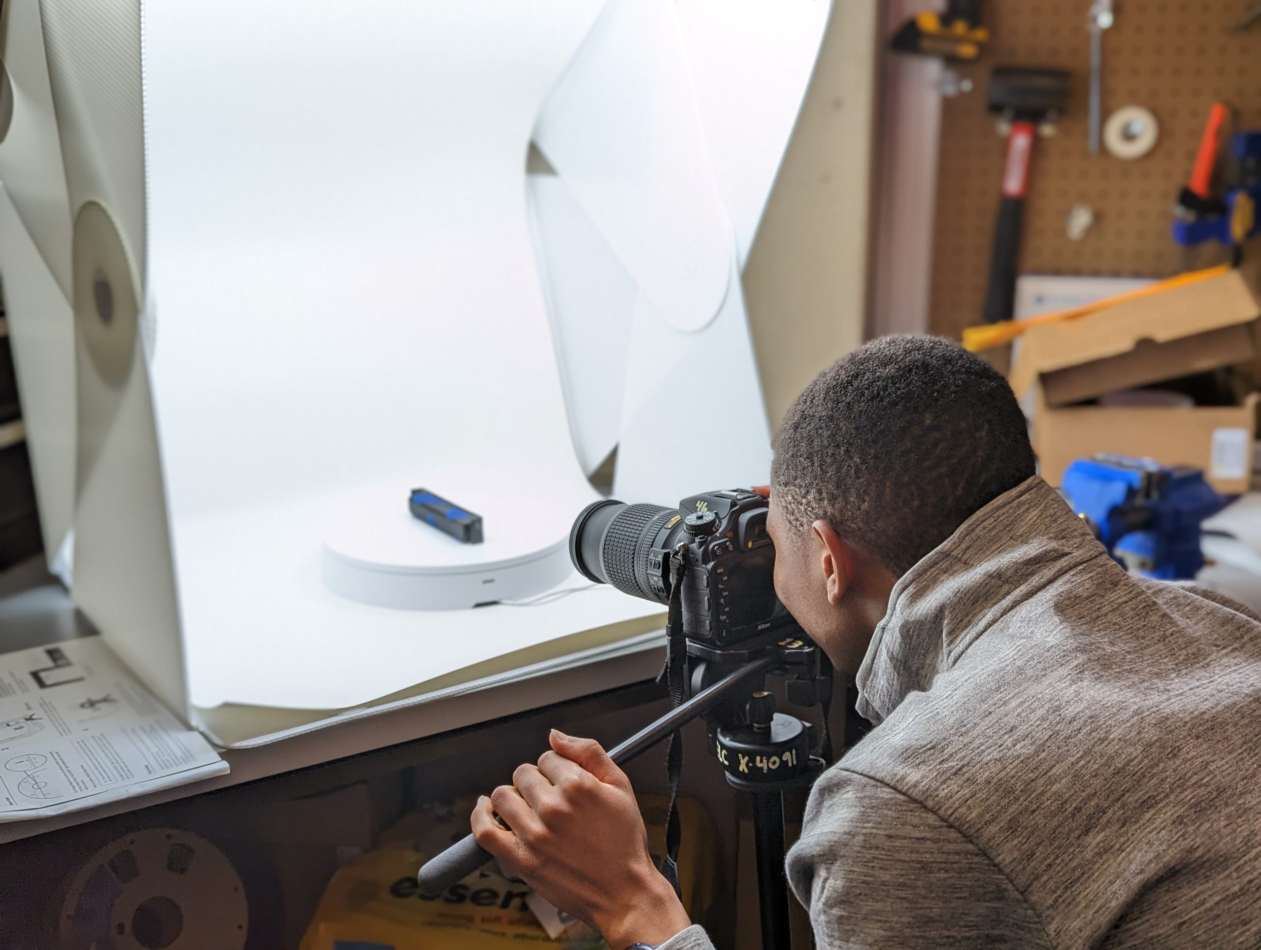
Milton taking pictures for photogrammetry

Now that the two biggest giants had been slayed, it was time to move on to the next step: taking pictures of the object. Taking shots for photogrammetry is very similar to doing stop-motion animation. You take a picture of the object, move it at a small angle (between 5-15 degrees) by hand or with a turntable (a rotating disc), and take another picture. Then you repeat this process until the object has rotated completely, change the camera angle (e.g., by taking shots from the top of the object), and redo the whole process again. This can be quite tedious, especially if you have to do it by hand, but luckily for me, the Makerspace had recently bought a new automated turntable, so I didn’t have to rotate the object manually. I also got to be the first to create a documentation guide for other Makerspace student workers to more easily be able to utilize the turntable in the future!

Alignment Process

Once the photos were ready, the next step was to analyze them using photogrammetry software. I turned to Agisoft Metashape, a powerful program that receives pictures of an object from different angles and analyzes them to create a 3D depiction of the object. The software first finds common points between the various images, called anchor points, and calculates their relative distances, allowing the software to place them in a 3D place. This process is called alignment.

Unfortunately, despite my efforts to aid the software by covering the object with matte blue tape to reduce its shininess and darkness, the obsolete plastic object did not align properly in Metashape. While I could not pinpoint the exact reason, I suspect it was due to its hollow shape, which made it challenging for the software to capture points on the inner surfaces, especially the corners. It was quite disappointing to get these results, especially after having had to wade through Metashape’s jungle of commands, but that was certainly not the end of it all. I decided to try a different approach – raise an older desktop 3D scanner from the grave!

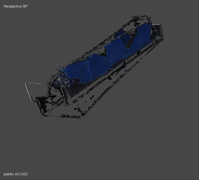
Misalignment in Metashape

Misalignment in Metashape

The Hewlett Packard (HP) 3D Structured Light Scanner

The 3D David Scanner (now called the HP 3D Structured Light Scanner) works by projecting light onto a subject and capturing the reflection. It measures the time taken for the light to return, determining the distance of each point. These points, represented as XYZ coordinates, are collectively used to digitally reconstruct the object in a 3D space. I intended to use the structured light scanner as an alternative to Metashape software because it allows more control over the alignment process. For example, you can select two specific images you want to align and tell the software how you want them to get aligned. In addition, the scanner features a projector that sheds light on the project you’re scanning, as well as a calibrated background panel, allowing for greater detail to be picked up. 

HP 3D Structured Light Scanner

HP 3D Structured Light Scanner

A Bit of Scanner Surgery

Using the HP 3D Structured Light Scanner

Using the HP 3D Structured Light Scanner

The Makerspace’s HP scanner unfortunately hadn’t been functional in over three years. The camera was not working, and the scanner’s software could not make exports due to licensing issues. I updated the device’s software and installed new camera drivers, and in no time, the scanner was fully functional again. I then scanned the obsolete plastic object with the structured scanner. Unfortunately, the results were unsatisfactory. It resolved the prior alignment issue with Metashape, but the digital model had thin walls and holes on some of its surfaces, making it impossible to print. 

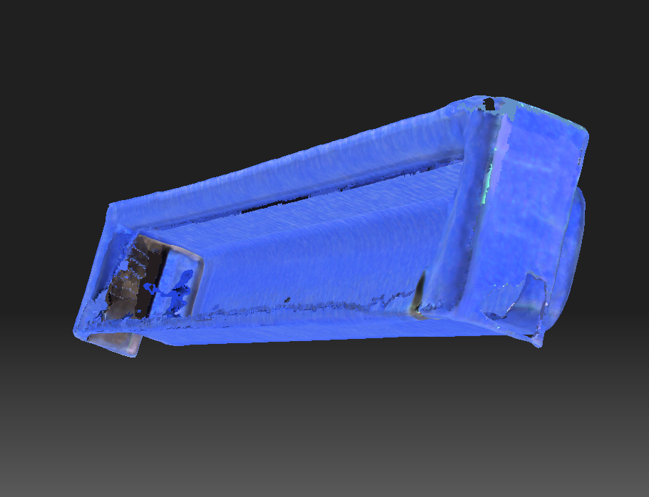
Thin walls and holes in the structured light scanner model

Thin walls and holes in the structured light scanner model

Building from the Ground Up with Fusion 360

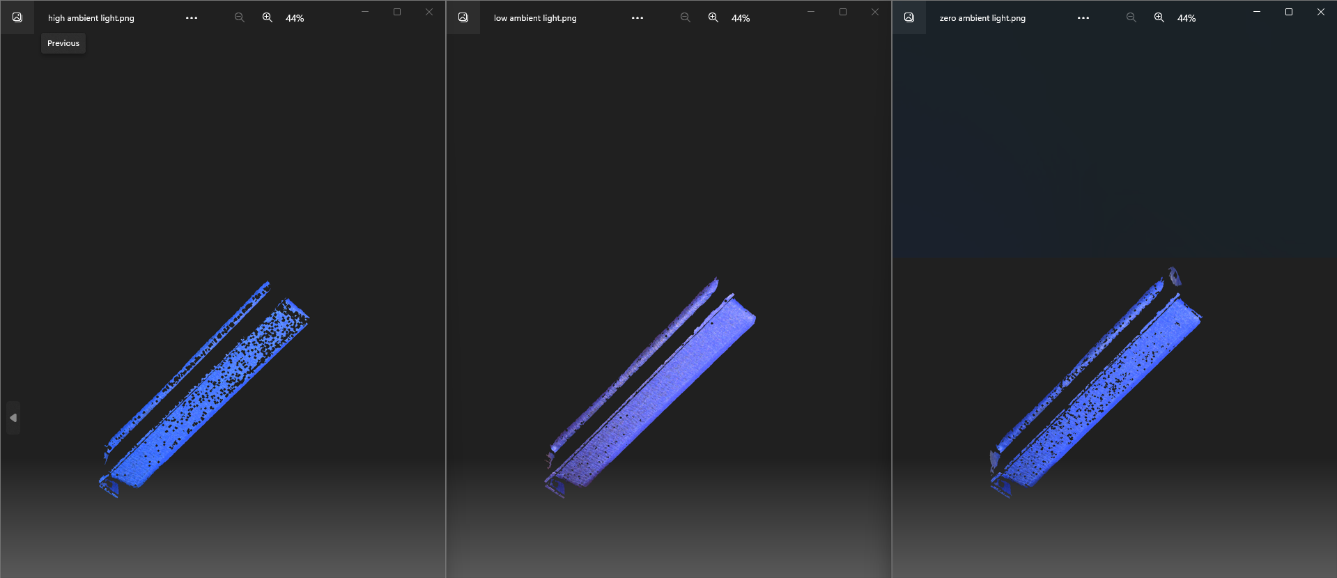
Results of different lighting setting in HP 3D Structured Light Scanner

Results of different lighting setting in HP 3D Structured Light Scanner

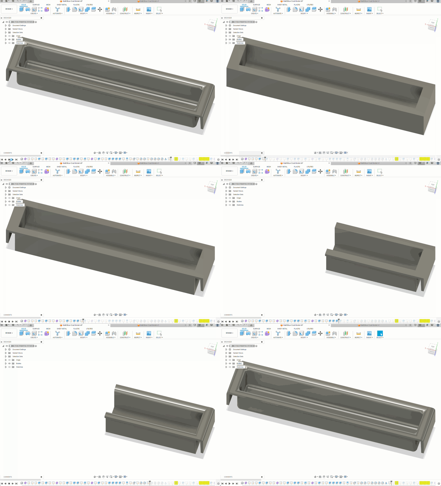
After trying out different strategies with the HP 3D Structured Light Scanner, such as different light settings, but still not getting good results, David suggested a different method – building the model from scratch! Excited to try out new software (and get a break from the structured scanner!), I began exploring Fusion 360 tutorials and documentation. Autodesk Fusion 360 is a Computer-Aided Design (CAD) software with applications across various sectors, including manufacturing, engineering, and electronics. It allows one to create a simple sketch of a model and build it into a solid model with precise dimensions. You can even add simulations of real-world features such as material sources and lighting. 

Of course, this new, complicated, piece of software came with its challenges. For example, I had to know the dimensions of the fillets (the arcs) inside and outside my object. A little creativity combined with a pair of vernier calipers and a piece of paper did the job. Another challenge was understanding the timeline feature of Fusion 360, one of the most important features of the program, which allows you to record your progress and go back to a certain point. Researching online and getting help from a friend (shoutout to Oscar!) with more experience in Fusion 360 proved helpful in better understanding the software. 

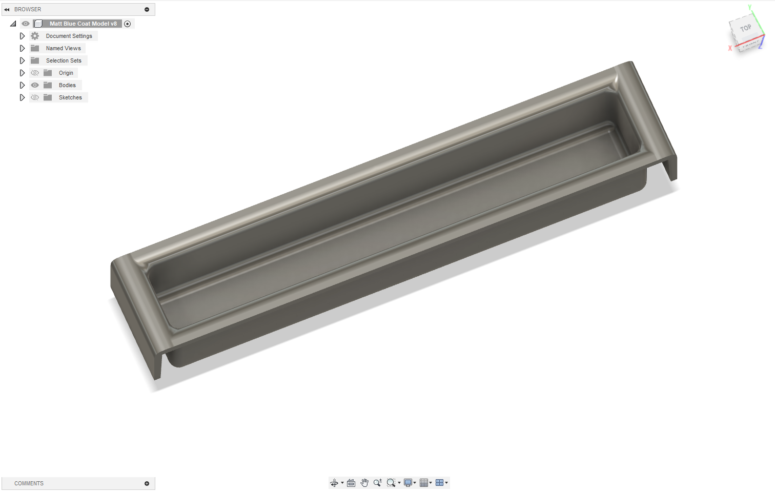
Successful Fusion 360 model of the obsolete plastic object

Successful Fusion 360 model of the obsolete plastic object

Fusion 360 timeline for modeling the obsolete plastic object

Fusion 360 timeline for modeling the obsolete plastic object

The Obsolete Plastic Object Was No Longer Obsolete

Finally, after several days of learning Fusion 360 and incrementally building a model, the obsolete plastic object was no longer obsolete. I produced an accurate model of the object and printed several copies, which Professor Koné was more than happy to receive. His files had regained their home, and time spent scouring eBay and Amazon for a nameless object had come to an end!

The red part (right), is the new clone of the original black “obsolete plastic object” (on left). Files are once again safely organized.

The red part (right), is the new clone of the original black “obsolete plastic object” (on left). Files are once again safely organized.

Conclusion

My experience working on photogrammetry and 3D modeling at the Makerspace was certainly full of twists and turns but definitely worth it. I learned how to use more than three very complicated software applications, significantly improved the Makerspace photogrammetry procedure (reduced a 3-month process to 1-2 days), and approached new challenges with an open mind.

Prof. Koné and myself holding the original (covered in blue tape) and a newly printed black 3D “obsolete” plastic object

Prof. Koné and myself holding the original (covered in blue tape) and a newly printed black 3D “obsolete” plastic object

Next Steps

I look forward to exploring other methods of photogrammetry, particularly ones that require less equipment, such as those that use only a smartphone. Reality scan is one promising alternative that can create lower-resolution scans and models in less than 15 minutes. With new technologies coming out every day, there are many avenues to explore, and I’m excited to discover better methods. 

Screenshot: Experimenting with the Reality Scan smartphone app

Screenshot: Experimenting with the Reality Scan smartphone app

Truly-Local Internet: The PiBrary Project

Figure 1: A Raspberry Pi 4 Model B

Figure 1: A Raspberry Pi 4 Model B

If a local organization has important information for its neighbors, is there a way it can broadcast directly to them without bouncing the data to Toronto and back? I grew up here in the Berkshires, and have recently joined the Office of Information Technology (OIT) at Williams. Thinking about Williams College’s commitment to community service and support, my project goal was to demo a low-cost, low-maintenance device which a local organization could use to easily broadcast information and resources over WiFi directly to nearby cell phone users through familiar, standard methods — (1) connecting to a WiFi network, and (2) navigating to a website address in a browser — without needing national or global infrastructure, or specialized equipment or technical skills on either side of the connection. Such an “internet-in-a-box” model could have useful applications in emergency scenarios, but also could provide curated information or resources digitally to multiple people in other specific, time-limited places and moments — for example, at a festival, workshop, teach-in, or other community event.

Figure 2: Wilmington VT, a mere 40-minute drive from Williams.

Figure 2: Wilmington VT, a mere 40-minute drive from Williams.

Let’s give this idea some real context. Imagine a small town in nearby southern Vermont – say, Wilmington. It’s late August, and a storm rips through, dropping 8 inches of rain in 24 hours, washing out roads and bridges, and knocking cell towers and internet infrastructure offline, leaving you without any connectivity for days. Local fire, rescue, and police services, town government, even your electric company, typically use websites, social media, and text messages to communicate critical information — but now, those methods don’t work. Where can you go for information regarding emergency food, shelter, medical care? Is the water safe to drink? When will power be restored? Where are the downed power lines and flooded roads? You’re both literally and figuratively in the dark.

No need to imagine: this actually happened in 2011, with Tropical Storm Irene. Superstorm Sandy in 2012 presented a similar case. And just this April, a single fiber optic cable damaged by a late-season snowstorm shut down Berkshire businesses for a day.

Truly local connections literally do not exist on the modern Internet. Are you on campus and want to view the williams.edu website? That data lives on a server in Toronto, and travels through 6 or 7 intermediary servers (including places like New Jersey and Ohio) before it lands in your cell phone’s browser (also producing 0.5g CO2 each visit). Under normal conditions, this globalized infrastructure is reliable, and has important benefits. But it’s useful to think about the edge cases. Climate change is bringing more unpredictable severe weather events. Rural areas like ours are often underserved by internet service providers (ISPs), which often have little financial incentive to invest in maintaining or expanding infrastructure.

This post offers a guide to creating your own DIY hyper-local webserver. If you can write a webpage (in plain HTML) and are open to my guidance in using a command line: follow along!

Required Equipment and Steps

Figure 3: Required hardware: Raspberry Pi 4 Model B, Power Supply, PiSwitch, and 32GB MicroSD card with Raspberry Pi OS installed.

Figure 3: Required hardware: Raspberry Pi 4 Model B, Power Supply, PiSwitch, and 32GB MicroSD card with Raspberry Pi OS installed.

I decided to build using a Raspberry Pi 4 Model B single-board computer. The Pi is about the size and weight of a deck of cards, and runs a version of Linux, an open-source operating system (OS).

There were two tweaks I determined were necessary to make the Pi ready to play the role I imagined. First: I needed to enable the Pi to act as a webserver, rather than a desktop. Second: I needed to adjust the Pi’s built-in WiFi connection to broadcast, rather than receive, a WiFi signal.

Tweak 1: Webserver Setup

Globally, 30% of all known websites use Apache, an open-source webserver software launched in 1995. I installed Apache on the Pi through the command line, using the command:

sudo apt install apache2

Now, any content I wanted to broadcast to other users I could simply place into the preexisting folder at /var/www/html/. I wrote a home page, an “about” page, and created 4 subfolders loaded with some open-licensed content (PDFs, audio and video files). You can check out my content (and adapt it if you like!) at github.com/gpetruzella/pibrary.

Tweak 2: Adjusting WiFi to Broadcast

I then used the following on the command line to tell the Pi to broadcast as a WiFi hotspot:

sudo nmcli device wifi hotspot ssid <my-chosen-hotspot-name> ifname wlan0

(The Pi’s built-in WiFi device is named “wlan0”; I chose to name my hotspot “pibrary”.)

Now, the Pi was broadcasting a WiFi hotspot, which other devices would be able to see and connect to. But… I wanted to make sure this happened automatically every time the Pi was switched on. To accomplish that, I needed to find the new hotspot’s UUID, then use that in one final configuration step. I found the hotspot’s UUID by running:

nmcli connection

This displayed a table with multiple rows: I found the “pibrary” row and copied its UUID. Then, I ran:

sudo nmcli connection modify <pibrary’s UUID> connection.autoconnect yes connection.autoconnect-priority 100

With this modification completed, simply switching on the Pi will automatically start broadcasting a WiFi signal (as a “hotspot” or source), with no extra steps.

Connecting from a Nearby Mobile Phone

screenshot of the homepage at pibrary.local.

Figure 4: Viewing the homepage at pibrary.local.

Now, the Pi was both “serving” webpages, and broadcasting a WiFi hotspot. Even without Internet — such as during power outages — any nearby user could find and connect to the WiFi hotspot on their phone… but what “web address” would they type in the browser to reach the content? The final piece of the puzzle requires knowing the Pi’s “hostname”. When I first set up my Pi, I gave it the hostname pibrary (just like the hotspot). The domain name

.local

is a special-use domain name reserved for local network connections. So, once a cell phone has connected to the “pibrary” WiFi hotspot, that user can type

pibrary.local

into the browser to reach the homepage I had set up in Tweak 1. Finding your own Pi’s hostname is as easy as entering the following on the command line:

hostname

Experiencing the Local Website

Below are a few screenshot examples of navigating the PiBrary resources from an Android phone.

screenshot of streaming an open-licensed video.

Figure 5: You can stream an open-licensed video.

screenshot: accessing directories of open-licensed learning resources.

Figure 6: You can access directories of open-licensed learning resources.

Figure 7: You can view PDFs.

Figure 7: You can view PDFs.

Challenges and Future Expansions

One limitation of this implementation is the range of consumer-grade WiFi: the maximum signal distance is roughly 90 meters under ideal conditions. The HaLow (802.11ah) standard offers up to 1km of range; but today’s consumer cell phones aren’t built to use that standard. One solution could use HaLow to send data from one Pi to another – say, one in town hall and another at a fire station (if each has an inexpensive HaLow module installed), with each one serving its own nearby neighborhood over standard WiFi. Alternatively, even off-the-shelf home mesh or WiFi “extender” hardware could improve the reach of this model without significant cost.

A second challenge: maintaining and editing content. My ideal use-case was for non-technical community members (e.g. in public safety or town government) to easily push information, announcements, etc. However, this demo succeeded because I knew how to edit and manage webpage content directly (i.e. by writing HTML). For a non-technical community member, using the bare Apache webserver this way could be a significant barrier to easy deployment or quick posting, especially in the environment of a public emergency. To address this, I would like to explore whether the YunoHost open-source server management application is compatible with the PiBrary project. YunoHost offers a very familiar and robust web editing interface, plus other possible additional services, such as email hosting.

In terms of sustainability, a lightweight Pi-hosted local site radically reduces the total carbon impact of each site visit, even taking into account the fact that Williams’ website is “hosted green”. A fascinating expansion of this project would be to use sustainable web design principles and standards as a standard part of the college’s digital presence.

Finally, privacy. Unlike ordinary internet browsing, which has many elements protecting and encrypting the flow of data, this demo creates a simple, direct, unencrypted WiFi network. (You may have noticed the “insecure alert” icon next to the address in some of the screenshots above.) In the absence of any technical trust guarantees, this setup is suitable only for very specific cases where the connection between server and client is based on human trust – like in a local community!

Thanks to David Keiser-Clark, Makerspace Program Manager, and to my colleagues on the Academic Technology Services team, for their support in developing this prototype.


Simulating Spaces with Augmented Reality (AR)

Fig.1 This is me standing in front of Chapin Hall, using my tablet to view my AR model (see below) superimposed as a "permanent object" onto the Williams campus.

Fig.1 This is me standing in front of Chapin Hall, using my tablet to view my AR model (see below) superimposed as a “permanent object” onto the Williams campus.

At age nine, I had a bicycle accident (and yes, for those who know me, I can’t swim, but I can pretty much ride a bike, thank you!). It was not that unusual compared to how you usually fall from a bike: I was going up perhaps faster than what my mom allowed me at the time, and I bumped into a really, really, BIG rock. In great pain, someone nearby picked me up and, crying very much, I said: “I want to go home, give me my tablet.” A very Gen-Z answer from me, and I don’t recommend that readers have such an attachment to their devices. But let’s be honest—would I have been in such a situation at the time if I was peacefully playing the Sims instead of performing dangerous activities (such as bike riding) in real life? Is there a fine line between real and virtual? Can I immerse myself in a virtual environment where I *feel* like I drive without actually driving *insert cool vehicle*?


Fig. 2: I created this sketch of "maker space" in Procreate on my tablet.

Fig. 2: I created this sketch of “maker space” in Procreate on my tablet.

Augmented Reality (AR) is something I have been interested in learning more about as an internet geek. Although I count stars for a living now (I am an astrophysics major), I am still very much intrigued by the world of AR. Whenever there is a cool apparatus in front of me, I take full advantage of it and try to learn as much as I can about it. That’s why one of my favorite on-campus jobs is at the Williams College Makerspace! It is the place where I get to be a part of a plethora of cool projects, teach myself some stuff, and go and share it with the world (i.e., as of now, the College campus and grand Williamstown community!). Fast forward to my sophomore year of college, Professor Giuseppina Forte, Assistant Professor of Architecture and Environmental Studies, reached out to the Makerspace to create a virtual world using students’ creativity in her class “ENVI 316: Governing Cities by Design: the Built Environment as a Technology of Space”. The course uses multimedia place-based projects to explore and construct equitable built environments. Therefore, tools like Augmented Reality can enhance the students’ perspectives on the spaces they imagine by making them a reality.

This project could not have been possible without the help of the Makerspace Program Manager, David Keiser-Clark. He made sure that there was enough communication between me and Professor Forte so that deadlines for the in-class project completion were met, as well as the Williams College “Big Art Show”. In short, my role was to help students enhance their architectural designs with augmented reality simulations. This process involved quite a few technical and creative challenges, leading to a lot of growth as a Makerspacian, especially having no background in AR before taking part in this project!

Choosing Tools and Techniques

My role in this project was to research current augmented reality softwares, select one, and then teach students in the course how to utilize it. In consultation with Giuseppina and David, we chose Adobe Aero because it’s free, easy to use, and has lots of cool features for augmented reality. Adobe Aero helps us put digital stuff into the real world, which is perfect for our architectural designs in the “ENVI 316: Governing Cities by Design” course. I then set up a project file repository and inserted guides that I created, such as “Interactive Objects and Triggers in Adobe Aero” and “How to Use Adobe Aero”. This documentation is intended to help students and teaching assistants make their own AR simulations during this — and future — semesters. This way, everyone can try out AR tools and learn how to apply them in their projects, making learning both fun and interactive.

AR Simulations: My process

Fig. 3: I have successfully augmented reality so that, viewed through a tablet, my "maker space" 3D model now appears to be positioned in front of Chapin Hall at Williams College.

Fig. 3: I have successfully augmented reality so that, viewed through a tablet, my “maker space” 3D model now appears to be positioned in front of Chapin Hall at Williams College.

Once we had all the tools set up with Adobe Aero, it was time to actually start creating the AR simulations. I learned a lot by watching YouTube tutorials and reading online blogs. These resources showed me how to add different elements to our projects, like trees in front of buildings or people walking down the street.

Here’s a breakdown of how the process looked for me:

  1. Starting the Project: I would open Adobe Aero and begin a new project by selecting the environment where the AR will be deployed. This could be an image of a street or a model of a building façade.
  2. Adding 3D Elements: Using the tools within Aero, I dragged and dropped 3D models that I previously created in Procreate into the scene. I adjusted their positions to fit naturally in front of the buildings.
  3. Animating the Scene: To bring the scene to life, I added simple animations, like people walking or leaves rustling in the wind—there was also the option to add animals like birds or cats which was lovely. Aero’s user-friendly interface made these tasks intuitive, and videos online like this one were extremely helpful along the way!
  4. Viewing in Real-Time: One of the coolest parts was viewing the augmented reality live through my tablet. I could walk around and see how the digital additions interacted with the physical world in real-time.
  5. Refining the Details: Often, I’d notice things that needed adjustment—maybe a tree was too large, or the animations were not smooth. Going back and tweaking these details was crucial to ensure everything looked just right. Fig. 1, 2 & 3 show an example of a small project I did when I just started.

Final Presentation: The Big Art Show

Figures 4 and 5 show side-by-side comparisons of real-life vs AR spaces as presented in the Williams College “Big Art Show” in the fall semester 2024. The student who used the AR techniques decided to place plants, trees, people and animals around the main road to make the scene look more lively and realistic. 

Fig. 4: Exhibition at the "Williams College Big Art Show" featuring 3D printed houses and buildings alongside a main road.

Fig. 4: Exhibition at the “Williams College Big Art Show” featuring 3D printed houses and buildings alongside a main road.

Fig. 5: Live recording of an AR space in Adobe Aero, enhanced with added people, trees, and birds to create a more memorable scene.

Fig. 5: Live recording of an AR space in Adobe Aero, enhanced with added people, trees, and birds to create a more memorable scene.


Lessons Learned

Reflecting on this project, I’ve picked up a few key lessons. First, jumping into something new like augmented reality showed me that with a bit of curiosity, even concepts that seem hard at first become fun. It also taught me the importance of just trying things out and learning as I go. This project really opened my eyes to how technology can bring classroom concepts to life—in this case, the makerspace!—making learning more engaging. Going forward, I’m taking these lessons with me.

Resurrecting the Ancient: A 3D-Printed Chinese Oracle Bone Finds a New Home at Williams

When students in ASIA 325 / ARTH 325: The Arts of the Book in Asia walk into class, they are greeted by an object that feels both ancient and cutting-edge: a 3D-printed replica of a 3,000-year-old Chinese oracle bone. What they may not realize is the complex and fascinating journey that brought this piece into their classroom, a story of international collaboration, digital preservation, and creative craftsmanship.

The 3D-printed replica of the Chinese Oracle Bone

The 3D-printed replica of the Chinese Oracle Bone

From Oracle to Object

Using open-access scans from the Cambridge University Library, and with permission from Professor Dominic Powlesland, who co-holds copyright with Cambridge, the team downloaded and processed a high-resolution 3D model of Oracle Bone CUL.52.

“We don’t have any oracle bones on campus, and it wouldn’t be ethical to acquire one. But thanks to digital tools and Cambridge’s generosity, we can still bring one into students’ hands,” said Anne Peale.

3D print ready for resin.

3D print ready for resin.

The etchings after resin.

The etchings after resin.


From Data to Artifact

The project’s journey from digital file to physical artifact unfolded in several stages:

  • January 30, 2023: STL files arrived from Cambridge.
  • February 1: The first prototype was printed using FDM (fused deposition modeling).
  • February 7: A final resin print was scheduled, scaled to preserve the original details.
  • March 16: Print studio technician Javier Robelo applied etching ink, transforming the object’s surface from shiny resin to an aged, textured finish.

“To my eyes, the etching ink transformed the resin print into something that feels older and more authentic,” said David Keiser-Clark.

Ink covered 3D print.

Ink covered 3D print.

Ink resin used to age the 3D print.

Ink resin used to age the 3D print.


A Teaching Tool with Character

Javier Robelo (Print Studio Technician) added water soluble etching ink to the resin print, then wiped it off using tarlatan wiping fabric. This process allows only the ink within the crevices to remain and that greatly the enhances visible contrast of the 3,000 year old markings.

Javier Robelo (Print Studio Technician) added water soluble etching ink to the resin print, then wiped it off using tarlatan wiping fabric. This process allows only the ink within the crevices to remain and that greatly the enhances visible contrast of the 3,000 year old markings.

By late March, the project reached completion. Both Peale and Mumtaz were impressed by how the replica captured the visual depth and tactile quality of the original oracle bones.

“WOW, what a transformation! I can’t believe how much more visible the characters have become. May I share this with Dominic at Oxford?” wrote Peale in response to the final version.

“It is really looking like the real deal now! We would be delighted to teach with this,” added Mumtaz.

Acknowledging the Origins

This project would not have been possible without the digital preservation work of Cambridge University Library and Professor Dominic Powlesland. All future educational materials will include the following acknowledgment:

Oracle Bone, CUL.52. With thanks to Cambridge University Library and Professor Dominic Powlesland for making these scans available for research and teaching.

What’s Next

A second resin print, featuring the same inked detailing, will be produced as a gift for Professor Powlesland. The team is also exploring new materials and inking techniques to enhance texture and durability. The replica will continue to be a highlight of ARTH 325: The Arts of the Book in Asia, giving students a tangible connection to early Chinese history and script. Through this collaboration, ancient writing and modern technology meet in a way that deepens understanding and preserves cultural heritage.

TIDE Grant: Sustainable and Reusable STEM Learning Kits for Students in Under-Resourced 5th and 6th Grade Classrooms

Written by Divine Uwimana ’27 and Alice Sore ’27. 

Introduction

Our latest prototype of the car includes a winding mechanism, which will act as an additional modification of the base kit.

Our latest prototype of the car includes a winding mechanism, which will act as an additional modification of the base kit.

In an ideal world, students would have equal access to education, but that isn’t the case. While some schools have the latest learning technologies, hands-on opportunities, and all the funding they need, others are trying to give students the highest quality education they can without access to these resources. Worst of all, the schools negatively impacted are often in historically underrepresented communities, often ones with large populations of people of color, perpetuating a cycle of poverty. While brainstorming ways of helping our local communities as part of the TIDE Grant (Towards Inclusion, Diversity, and Equity Grant) proposal, providing more equitable access to STEM education was a clear way we thought we could make an impact. Building these STEM kits is a way we Williams students can use our education and access to help build up the community around us.

What is Hands-On STEM Education?

Hands-on STEM education uses physical interaction to provide real-world experiences that help reinforce the concepts being taught. While they can be helpful to the learning process, these experiences are often expensive. Whether it’s premade kits that can cost upwards of 40 dollars a student or involve costly field trips, these experiences often don’t fit within the budgets of schools. This disparity is critical to solve because studies have shown that hands-on learning opportunities help students retain what they learn better than standard learning methods such as lecturing. The problem is exacerbated in the education of younger students (K-6 range) because younger children’s lower attention spans can cause them to lose focus more quickly in the absence of active and experiential pedagogy.

This problem doesn’t only exist in a classroom setting. Many attempts have been made to bring hands-on learning to the home as supplemental education and homeschooling tools; however, cost is even more of a problem here. One of the largest companies currently producing these kits for home use is Crunch Labs. While they are similarly priced, averaging around $30 a kit, the requirement to purchase a monthly subscription typically results in costs of $300 or more per child. Also, Crunch Labs and other kits built for a home environment are often not reusable.

Access to hands-on STEM education is so important because high-quality STEM education improves students’ creativity and problem-solving skills. Research has shown that exposing kids to STEM in elementary school – especially between the first and third grades – provides students with the foundation they need to succeed in STEM-field careers. According to the research, U.S. adults with 1-2 years of experience in the workforce have reported the highest exposure to STEM concepts in elementary school. Between the ages of 5 and 8, 46% of this population experienced a STEM-related track in school and 53% of this population currently works in a job that is either entirely or heavily involves STEM – by far the largest percentage of any sector of jobs in the workforce. This suggests that exposing students to STEM at a young age captures their imagination and keeps them interested in science, technology, engineering, and math jobs early in their careers.

As student workers in the Makerspace, Divine Uwimana ‘27 and I, Alice Sore ‘27, met and collaborated with Paula Consolini, Adam Falk Director of the Center for Learning in Action, Tanja Srebotnjak (Director of the Zilkha Center for Environmental Initiatives), and David Keiser-Clark (Makerspace Program Manager). We identified a few critical criteria for STEM kits:

  1. Our STEM Kits need to be as low-cost as possible to produce. To ensure this, we must find creative ways to reduce material usage and implement supplies students may already have in their classrooms into the kits.
  2. We must design STEM kits to leverage existing lesson plans and learning requirements to ensure that the STEM kits fulfill the educational needs and standards set out by organizations like the Department of Education. 
  3. The STEM Kits must be designed to be reusable, durable, and sustainable, using sustainably sourced and produced materials wherever possible.

Brainstorming

Divine and I began the brainstorming process by researching existing STEM kits currently available on the market and how we might further improve them for our demographic group with respect to the aforementioned criteria. Since we both had little experience in the field beforehand, we wanted to understand better the design features other organizations used to create highly engaging STEM kits. Some of the qualities we observed that we believe we should replicate are listed below:

  • A good STEM kit is highly interactive. Parts of the kit, especially mechanical parts, should be designed so that students can visually see what is happening and how the action they are putting in is causing the final result.
  • A good STEM kit should not be a “one and done.” Ideally, a STEM kit will have multiple stages that allow students to build upon a product in stages, introducing new concepts or building on previous concepts.
  • A good STEM kit should be a manageable length. Even if students are having fun, dragging it out too long risks boring the students and causing the learning aspect to be ineffective.
  • A good STEM kit should be fun yet educational. This means balancing the kit to both be rich in academic concepts and interesting to keep them engaged.
  • A good STEM kit should encourage teamwork and cooperation. It should allow kids to work together to build their social skills while learning.
  • A good STEM kit should allow “trial and error.” It should enable the kids to learn from mistakes and thus build their problem-solving skills.
  • A good STEM kit should be simple yet visually complex. Just because the final mechanism is a complex contraption doesn’t mean the process of assembling it can’t be simplified and streamlined.
Front and back views of the mechanical scotty dog kit from Carnegie Mellon University.

Front and back views of the mechanical scotty dog kit from Carnegie Mellon University.

During our design process, we also got to experience assembling a STEM kit first-hand, specifically the mechanical Scotty dog kit we received from Carnegie Mellon University, courtesy of Professor Bill Nace and Professor Robert Zacharias. The materials used to assemble it are easy to manufacture, primarily made of thin sheets of wood and acrylic with 3D-printed plastic parts. The design is simple but very interesting; a single motor in the middle drives both the tail wagging on the back and the head bobbing on the front through a system of gears on the back. The head is made to bob up and down in a specific pattern through the radius of the spinning piece increasing or decreasing as it turns, creating a pattern of head movements that feels random. The tail spins on an arm and is locked upright using a bracket, making the tail wag back and forth with a simple spinning motion. Finally, all of this is controlled with a light sensor, allowing the user to control the speed of the motion by raising or lowering their hand above it. All these mechanisms combined to create a fascinating kit from a design standpoint, with a lot of interactivity and interesting mechanisms on display while being very quick for us to reassemble, even without instructions.

From this experience, we better understood how to design an effective STEM kit. Then, we started brainstorming ideas for STEM kits that we could create. At the end of this brainstorming, we ended up with three designs we wanted to develop further. The first is a model car, which would use a wind-up mechanism built by students to showcase the properties of potential and kinetic energy. The second idea is an energy kit expansion for the car, allowing students to electrify it while teaching them the basics of electricity and explaining renewable solar energy concepts. Finally, the third idea is a solar system kit, which would be focused on having students assemble a solar system model to teach about the planets in our galaxy and our place in the universe. With these initial ideas, we started prototyping the model car kit.

Prototyping the Model Car Kit

An initial prototype for the base car kit, giving us an idea of what the final product may look like.

An initial prototype for the base car kit, giving us an idea of what the final product may look like.

The main idea of our wind-up car kit was simple. But, as with many projects, it quickly evolved into a complex design with many digital iterations and three 3D printed prototypes. For this first design, a 3D printed base would connect the two cardboard sides and help support the back axle, which would wind up using a rubber band attached to it and the frame. Wooden dowels would act as axles and bottle caps as wheels, so when you pulled it back, the car would launch forward using energy stored in the rubber band. 

While this was a great initial idea, we encountered some problems. First, cutting out the sides made of cardboard proved difficult because two holes needed to be cut in the middle of it for axles. Ultimately, we decided that the side pieces should be replaced with laser-cut wood in the final design, which would be reusable and easier for kids to work with while providing more structural rigidity. Another issue we discovered was that the rubber band would stay on the axle instead of coming unhooked at the end, catching it, and abruptly stopping the car. Our solution was to move the hook point for the rubber band forward so it had enough energy to detach itself from the axle at the end. We also had to ensure this expansion didn’t use too much plastic, as we hope to create all the filament ourselves using recycled PET from locally gathered plastic bottles. We ended up using a honeycomb pattern, often seen in structures that use empty space to save material resources while retaining structural integrity, and by implementing this we were able to save sufficient plastic such that the larger prototypes consumed less plastic than our smaller initial prototype.

Our first three prototypes for the 3D printed base, showing how it evolved to meet the project's needs while remaining efficient in plastic usage.

Our first three prototypes for the 3D printed base, showing how it evolved to meet the project’s needs while remaining efficient in plastic usage.

For our third prototype, we rounded and smoothed as many parts as possible to prevent sharp points or edges that can occur in 3D printing. We also did this to prevent sharp points from catching or breaking the rubber band. Finally, we modified the slot at the front for the rubber band to help the car retain it, even after it detaches from the axle.

The biggest problem we ran into was not with the design of the base but with the kit itself. Our initial idea was interesting but violated one of our initial design rules. The kit was just one thing: assembling the car with the rubber band. If we wanted to make an exciting kit, we had to make at least one additional stage involving more engineering and differently demonstrating the concepts of potential and kinetic energy. 

While looking for inspiration, we stumbled upon a design by a maker named Greg Zumwalt for a 3D Printable Wind-Up Car that used a simple mechanism to limit the speed, allowing it to move farther and longer after windup as opposed to a design like ours, which simply went at top speed after release. Looking into this project’s mechanics, we realized that a similar design could be perfect to demonstrate the ways energy can be modified in the process of converting from potential to kinetic energy. So, to better understand how the mechanics worked, we downloaded the files and began printing them out to design a similar mechanism within the constraints of our model kit.

It was at this moment that the Office of Institutional Diversity, Equity, and Inclusion announced that our application for a TIDE grant was accepted and that our STEM kit project would be funded. 

Next Steps

Our next steps are to complete the second expanded energy source for our car prototype, align that with curricular concepts, and then meet later this month with an elementary school teacher to share our project and hear initial feedback. We plan to incorporate that feedback into the car prototype and then next meet with that teacher’s class and observe student reactions to utilizing it. As we continue to build several STEM kits, our theme will be to test, demonstrate, observe, seek feedback, iterate, and repeat. We hope these kits might have a significant impact on elementary students’ education in the Berkshires.

Beyond Board Games: Exploring a 3D Printed Catan Boards’ Role in Creativity, Connection, and Vulnerability

Top view of hexes (and an easter egg in the sheep tiles!).

Top view of hexes (and an easter egg in the sheep tiles!).

Few technologies capture the imagination like 3D printing. The ability to bring digital designs to life and hold them in our hands ignites a creative spark within us–or maybe just me. One of my first encounters with detailed 3D printed objects was at the Berkshire Innovation Center (BIC), an organization in Pittsfield, MA dedicated to investing in the local community. BIC’s passion and ability to embody childlike wonder left a lasting impression, particularly in the form of a blue, square-shaped chainmail pattern. Defying its angular components’ design constraints, the chainmail moved with remarkable fluidity, which was fascinating to a person like me with a strong spatial and tactile memory. It was incredible to see where negative space was needed for movement and the precision with which the chainmail was printed. This is where the allure of 3D printing lies with most people–the ability to transform concepts into tangible objects. Even seeing others’ projects can have a profound impact on creativity.

This all brought me to my dear friend Mo (Mohammad Faizaan ‘23). As I sat in Lee’s booth waxing starry-eyed over a 3D printed Catan board I saw online, he mentioned that he had experience with Williams’ Makerspace and could help make this dream a reality. (Thank you, Mo!)

Interpersonal Connectivity of Catan

3D printed Catan hexes, complete with my favorite detail--red silos for wheat storage.

3D printed Catan hexes, complete with my favorite detail–red silos for wheat storage.

Beyond its status as a game, Catan offers valuable lessons applicable to real life. While the basics of resource management and investment strategies are readily apparent, the game’s social dynamics are equally intriguing. Depending on the group of players, the game can take on vastly different tones. On one hand, I have a group that is very much into competitive play (you know who you are ?) and is driven by the idea of winning at whatever cost, which features more individualistic motives and trading futures (because…you know…Williams). On the other hand, my preferred collaborative-based play has been lovingly dubbed “socialist Catan”–prioritizing mutual trades, collective advancement, and the fun of the game. But regardless of which group I play with, it’s always part of the fun for me to observe how different players navigate these dynamics and how they adapt to each situation—when to use the stick and when to use the carrot—which provides insights into an array of problem-solving approaches and interpersonal dynamics (and yes, I’m a psychology major).

The Joy of Sharing Worldbuilding

My daughter and I would paint on the floor and take pictures to remember the colors we used.

My daughter and I would paint on the floor and take pictures to remember the colors we used.

What started as a pursuit of visual appeal and a quirky gameplay experience unfolded into a heartwarming journey of discovery with my three-year-old. Stepping back from strategy, painting the stark white 3D printed pieces became an exploration of the ‘big picture.’ Discussing color, the significance of a base layer for depth, and her inquiry about why I painted the “pointy trees” one color and the “round trees” a different color led to conversations about the different types of trees and their similarities and differences. This colorful journey became a means for her to develop a general understanding of Catan’s terrains, insights into each terrain’s unique elements, and why they were crucial for settlement–to the point where she ensures each sheep hex touches a wheat hex “so they can eat!” I even snuck a little geometry in there, and, to this day, she proudly proclaims that “hexagons are the bestagons” (fun link if you’re interested!). Beyond strategy, economics, art, geography, and math, the process was a rich opportunity for sharing experiences, bonding, and transmitting knowledge to the next generation.

Struggles with painting and being vulnerable (but mostly the vulnerability part)

The detached tree hex still counts as lumber, so at least we're not 'missing the forest for the tree.'

The detached tree hex still counts as lumber, so at least we’re not ‘missing the forest for the tree.’

I am no artist. This admission is not fueled by self-deprecation but rather an acknowledgment of my pursuit to overcome a slight strain of perfectionism. This project has been fun…and stressful. Even when David saw the finished product and expressed his admiration, encouraging me to write this blog post and share my experience with all of you, my initial response was tinged with embarrassment. The echoing thought in my mind: “It’s not good enough.” Those pesky white spots that were just surprisingly difficult to get paint to, the accidental detachment of a tree (oops), the crooked lines, and the colors that didn’t quite achieve a perfect harmony. It all seemed like a lot. 

I am also no blogger! Posting this article is even more terrifying! Sharing imperfect paintings is one thing, but sharing imperfect words?! Terror! Sharing this with you all is challenging for me. It shines a spotlight on my areas of vulnerability, whether it’s the brushstrokes that miss their mark, the sentences that might not be as polished as I’d like, or even my experiences as a parent and student. But if I tell my daughter, “You can do hard things, ” then I can too. So I hope that this post can shine a light on the amazing capabilities of the Makerspace and encourage a few of you to see what it has to offer. They are all wonderful people who are excited to help you discover a few new facets of yourself! 

Thanks for reading.

(3D printing files can be found on Thingiverse by creator JAWong.)

Thanks to David Keiser-Clark, Makerspace Program Manager, for providing me an opportunity out of my comfort zone, the patience to wait until I felt ready to post this, and allowing me to share my wacky love of 3D printing, games, and my life side-quest of normalizing vulnerability.

Before printing the 3D borders, but we were eager to play!

Before printing the 3D borders, but we were eager to play!

Architecture in Slices: 3D Printing for the Big Art Show.

The Arts 314 exhibit in the Big Art Show

The Arts 314 exhibit in the Big Art Show

In my first Makerspace academic project, I jumped into the deep end. My role was to support Giuseppina Forte, the Assistant Professor of Architecture and Environmental Studies, and her students by preparing exhibition materials for the end-of-semester campus Big Art Show. I supported her two studio arts classes “ARTS 314 / ENVI 310 – Design for the Pluriverse: Architecture, Urban Design, and Difference” and “ENVI 316 / ARTS 316 – Governing Cities by Design: the Built Environment as a Technology of Space”. For ARTS 314, her students designed an architectural model of an outdoor community building, and for ARTS 316, they re-envisioned the Cole Avenue Rail Yard area of Williamstown into a river-side park. My role was to convert the students’ digital architectural designs into 3D-printed objects. What seemed straightforward quickly became a challenging—and amazing—learning experience filled with challenges and growth that I want to share. 

Prototyping

The first of many difficulties arose when I sliced, or readied, the models for the 3D printers. First, some files seemed to have problematic features deeper than the abilities of the FlashForge and Prusa slicer software repair algorithms. So, I spent some time learning MeshMixer and how to identify the Achilles heels of the models. In most cases, manually widening thin connections was sufficient. Second, some prints seemed impractical, if not entirely impossible. In some cases, these impractical features were easily removable without destroying the final product, like thin columns on B3. In others, features were inherent to the design, such as with A1, which posed a challenge for 3D printing due to its elevated, thin, and intricate spiral design. Finally, some prints, like B2, would just take an incredibly long time to print – up to 60 hours.

The models I would print. From top left to bottom right: A1, A2, A3, A4, A5, S1, S2, B1.

The models I would print. From top left to bottom right: A1, A2, A3, A4, A5, S1, S2, B1.

A prototype of A2

A prototype of A2

In a typical project, I would prototype each print and present them before starting any final prints. This helps to set expectations for what a 3D print looks like, how the pieces go together and allows me to get feedback on the prints. However, these prints proved particularly challenging to prototype for the above reasons. While I could get a couple of iterations of the simpler prints, many prints proved difficult to scale down due to their small and intricate details, and, in my mind, no prototype is worth 40 hours or 100 meters of filament because of the likelihood of repeated failed prints.


Crunch Time

For prints with exposed, flat surfaces like A4, printing upside down provided a smoother finish and allowed the prints to peel off of the plate more consistently

For prints with exposed, flat surfaces like A4, printing upside down provided a smoother finish and allowed the prints to peel off of the plate more consistently

However, dilly-dallying in this “half-prototyping” stage created a problem. Since I was hesitant to review an incomplete set with everyone, I mentally stayed in the prototyping phase, not starting any of the final prints. Instead, I spent this time optimizing the prints that I hadn’t been able to prototype. I ran tests to maximize the quality of the print while minimizing the filament used. While I can’t say that this time was wasted, since many of the optimizations helped me later, in hindsight, I wish that I had paid more attention to the time and started my final prints sooner, as I could have prevented much of the stress in the final time crunch.


I found that I was able to go as low as 8% infill on solid prints before jeapordizing structural integrity.

I found that I was able to go as low as 8% infill on solid prints before jeapordizing structural integrity.

The final week and a half of the project was a combination of epic stress and stellar production. It started with David Keiser-Clark, the Makerspace Program Manager, asking me if I thought it would be possible to finish and deliver the prints before the start of the show in nine days. I panicked. I had become so immersed in solving the technical issues that I had lost track of the delivery date. I sat down and figured out that the total printing time for this project would take ~240 hours. Had I immediately started two prints on the two working printers and ran them 24/7, the prints would have only finished three or four days before the deadline. I immediately put two prints on the printer and responded to David, cautiously telling him I thought I could finish them in time. 

A spectacular failure of one of the prints

A spectacular failure of one of the prints

My estimates couldn’t have been more wrong. My first two prints should have been relatively quick and easy, but when I returned to collect them I was greeted by two spaghettified clumps of white PLA. I reran both prints, praying that they were flukes, but of course, they weren’t. Within 5 minutes, both prints had failed again. I did a 20-minute calibration of both printers and reran the prints: the print in the FlashForge was successful, but the Prusa failed again. Time was slipping away, and only one printer was operating reliably. 


Removing Roadblocks

All four printers running smoothly!

All four printers running smoothly!

I reached out to David and explained the issue. He helped me configure the two out-of-commission Dremel printers, which seemed to be my saving grace. However, I transferred my slices to the Dremel and found that many of the round prints were larger than the Dremel’s base plate. This, combined with the fact that the Dremels struggled with finer detail in test prints added to my stress. However, after examining the models, I found that I could cut the larger files into smaller pieces, print them, and then later assemble and permanently glue them together. 

The final print of A2 and the tops of S1 and S2, unfortunately printed in different sizes.

The final print of A2 and the tops of S1 and S2, unfortunately printed in different sizes.

Six days before the show we had four working printers. The Prusa had been fixed (twice) and was churning out the finer detailed prints. The FlashForge was working on a piece of the largest print, which I had cut down to 30 hours (from 48) by increasing the layer height to the maximum of 0.3mm (75% of the nozzle diameter). Both Dremels were printing the remaining pieces of the largest print and we had received permission to use the Science Shop’s Ultimaker for A1, which was the most challenging, longest-running, and most likely-to-fail print in the entire project. For a moment, it looked as if the project would be done comfortably in time, with several days of cushion to spare.

Using natural supports used less filament, took less time, and failed less than vertical supports

Using natural supports used less filament, took less time, and failed less than vertical supports

One day later the situation flipped on its head. The filament for the Ultimaker, ordered in advance, failed to arrive. Three prints in the Makerspace failed. The filament roll on the FlashForge got tangled and caused a jam, the Prusa had spaghettified, and one Dremel printed the house sans the roof. I was able to find and solve a problem within the Dremel slicer software and recalibrate the Prusa, but for now, the FlashForge was out of commission. 

In hindsight, I had not anticipated the variance in scaling among different slicing softwares. The Dremel software defines its x-axis differently than the FlashForge software, which resulted in pieces that scaled poorly with the rest of the model. 

A copy of A1 printing on the FlashForge 1 day before delivery.

A copy of A1 printing on the FlashForge 1 day before delivery.

Three days before the show, I had somehow managed to print A2, A3, A4, A5, B1, and B3. We fixed the Dremel and set the most structurally fragile and complicated print (A1) to run overnight on all four printers. This would be our last chance. 

One day before the show, our final prints were completed: the Prusa and FlashForge succeeded, while both the Dremels failed. Of the two successful prints, the Prusa created a beautiful, highly detailed print. Unfortunately, I woke up with the flu and didn’t get to say goodbye to the prints, nor could I go to the Big Art Show. However, I got to see pictures and I was proud to support the students’ architectural work for the show, but, to me, the greatest value of this project was not in the prints themselves, but in the lessons that I learned and that I will take with me into my future work both in and out of the classroom. Specifically, I developed confidence in my ability to solve technical problems in a new medium while working under pressure and improved my capacities in project management.

The final collection of pieces

The final collection of pieces

Murphy’s Law

The Arts 316 exhibit in the Big Art Show

The Arts 316 exhibit in the Big Art Show

Murphy’s Law states that when something can go wrong, it will. Doubly so when you are under a time crunch. In hindsight, most of this pressure could have been avoided had I made an effort to timeline the project before the due date was imminent. When printing, you have to strike a balance between quality, material used, and time. Before the time crunch, I was trying to maximize quality and minimize the material used. However, the instant time became the driving factor, I swapped those priorities. All in all, it worked out, but if I had managed my time better I likely could have delivered just as good of a final product with less stress. 

Post Mortem

During this project, I discovered how fragile 3D printers are. We had four printers in the Makerspace, and I had to do a total of eight mechanical fixes. At some points, I felt completely defeated. It seemed like every successful print was counterbalanced by an awful grinding sound or a jammed PLA feed. This was not the first time I had ever 3D printed, but it was my first time tinkering with 3D printers. Admittedly, at the start of the project, I was so scared of breaking something that I barely opened the side panel before asking for help. The silver lining of the printers breaking so often was that I had the opportunity to learn how to fix them. During the project, David took a few hours to show me around each printer, explaining how they work and where they usually fail. This paid itself off in dividends. By the end of the project, I was more than comfortable repairing every single printer we had and reached a point where I didn’t even have to tell David when they were broken, likely saving him more time than it took to help me figure out how all of them work. I’m excited to take this experience and apply it to my next faculty project in the Makerspace.


Pixels or Petals? Comparing Physical vs. Digital Learning Experiences

Fig. 1: Isabelle Jiménez and Harper Treschuk outside the Williams College Makerspace located in Sawyer 248

Fig. 1: Isabelle Jiménez and Harper Treschuk outside the Williams College Makerspace located in Sawyer 248

Learning has not been the same since COVID. Just like the vast majority of students around the world, my classes were interrupted by the COVID pandemic back in 2020. After having classes canceled for two weeks, and in an effort to get back on track, my high school decided to go remote and use Google Meet as an alternative to in-person learning. Remote learning did not feel the same — this included using PDF files instead of books for online classes, meeting with peers over video conferencing for group projects, or taking notes on my computer and studying only digital material for exams. I cannot say that I was not learning, because that would not be the best way to describe it, but I can say that something rewired my brain and I have not been able to go back. Due to COVID and other factors, the use of simulations in schools may increasingly supplant hands-on learning and more research needs to be done not only on the implications for content knowledge but also for students’ development of observational skills.

Fig. 2: Sketchfab provides a digital view of the 3D model of a lily, accessible via an iPad interface. This interface allows the children at Pine Cobble School to engage with and explore the object in a virtual environment.

Fig. 2: Sketchfab provides a digital view of the 3D model of a lily, accessible via an iPad interface. This interface allows the children at Pine Cobble School to engage with and explore the object in a virtual environment.

Last week, Williams College students Isabelle Jiménez ‘26 and Harper Treschuk ‘26 visited the Makerspace to start a project for their Psychology class, “PSYC 338: Inquiry, Inventions, and Ideas” taught by Professor Susan L. Engel, Senior Lecturer in Psychology & Senior Faculty Fellow at the Rice Center for Teaching. This class includes an empirical project that challenges students to apply concepts on children’s curiosity and ideas to a developmental psychology study. Isabelle and Harper decided to analyze the ideas of young children following observations with plants, more specifically: flower species. The students plan to compare how two groups of similarly aged children interact with flowers. The first group will interact with real flowers and will be able to touch and play with the plants (Fig. 1), and the second group will interact with 3D models of the plants using electronic devices (iPads) that enable them to rotate and zoom in on the flowers (Fig. 2).  By analyzing the interactions of children with real and simulatory flowers, they hope to extend existing research on hands-on and virtual learning to a younger age range. Valeria Lopez ‘26 was the lead Makerspace student worker who assisted them in creating the necessary models which will be covered in this blog post. 

I was excited to learn about Isabelle’s and Harper’s project and quickly became involved by assisting them in using Polycam 3D, a mobile photogrammetry app. This app enabled us to quickly create three-dimensional digital models of physical flowers. We opted for photogrammetry as our method of choice due to its versatility—it can model almost anything given enough patience and processing power. Photogrammetry involves capturing a series of photos of an object from various angles, which are then processed by software to create a coherent three-dimensional digital model. To meet our project’s tight deadline, we decided to experiment with smartphone apps like RealityScan and Polycam, which offer a user-friendly approach to 3D object creation. While our standard photogrammetry workflow in the Makerspace provides greater precision, it requires more time and training because it uses  equipment such as a DSLR camera, an automated infrared turntable, a lightbox, and Metashape software for post-processing. Despite initial setbacks with RealityScan, we successfully transitioned to Polycam and efficiently generated 3D models. These models serve as educational resources for children, and since precise accuracy wasn’t necessary for this project, using a mobile app proved sufficient. This rapid approach ensures that the 3D models will be ready in time for the educational teach-in Isabelle and Harper are organizing at Pine Cobble School.

Process

Fig. 3: This scene features a daffodil placed atop a turntable, all enclosed within a well-lit box to enhance visibility and detail.

Fig. 3: This scene features a daffodil placed atop a turntable, all enclosed within a well-lit box to enhance visibility and detail.

We began our project by utilizing the photography equipment at the Makerspace in Sawyer Library to capture images of flowers in vases. Initially, we were careful to avoid using the provided clear glass vases because translucent and shiny objects are more difficult for the software to render correctly into accurate models. With the guidance of David Keiser-Clark, our Makerspace Program Manager, we selected a vase that provided a stark contrast to both the background and the flowers, ensuring the software could differentiate between them (Fig. 3 & 4).

Fig 4: In the foreground, a phone is mounted on a tripod, positioned to capture the flower's movement.

Fig 4: In the foreground, a phone is mounted on a tripod, positioned to capture the flower’s movement.


Setup

Our setup involved placing the flowers on a turntable inside a lightbox and securing the smartphone, which we used for photography, on a tripod. 

Troubleshooting

Fig. 5: Isabelle and Valeria (Makerspace student worker who participated in this project) analyze the 3D models in Polycam.

Fig. 5: Isabelle and Valeria (Makerspace student worker who participated in this project) analyze the 3D models in Polycam.

Our initial approach involved seeking out a well-lit area with natural lighting and placing the plant on a table with a contrasting color. However, we soon realized that the traditional method of keeping the phone stationary while rotating the subject wasn’t optimal for smartphone-designed software. While this approach is commonly used in traditional photogrammetry, our mobile app performed better with movement. Recognizing this, we adjusted our strategy to circle the subject in a 360-degree motion, capturing extensive coverage. This resulted in 150 pictures taken for each flower, totaling 450 pictures. Despite initial setbacks with two different photogrammetry apps, our second attempt with Polycam proved successful, allowing for more efficient and accurate processing of the models (see Fig. 5).

Results

Fig. 6: An alstroemeria flower model, which is one of the final models uploaded to SketchFab. The users will be able to interact with the object by rotating it in a 360 degree manner.

Fig. 6: An alstroemeria flower model, which is one of the final models uploaded to SketchFab. The users will be able to interact with the object by rotating it in a 360 degree manner.

We did not expect to need to do so much troubleshooting! In all we spent 45 minutes loading and testing three different apps, before settling on one that worked successfully. We are extremely happy with the end results. As a final step, I uploaded our three models to SketchFab to ensure that the children could easily access them across different devices (Fig. 6).

Next Steps

  1. Engage with Isabelle and Harper to gather their general impressions on the kindergarteners and first graders’ interactions with the real and digital 3D models while still maintaining complete confidentiality of the results.
  2. Take the opportunity to delve deeper into mobile photogrammetry tools and document the process thoroughly. Share this documentation with other makerspace student workers and the wider community to facilitate learning and exploration in this area. 
  3. Collaborate with other departments on similar projects that utilize 3D objects to enhance educational experiences, fostering interdisciplinary partnerships and knowledge exchange.

Postscript (May 10, 2024)

Isabelle and Harper report that their educational teach-in at Pine Cobble School using the 3D flowers was a success:

The students were all able to rotate them and zoom in and out. We noticed that as expected students in the virtual condition reported visual observations while students in the physical condition reported tactile observations as well (but no observations about smell) — interestingly, this didn’t affect the number of observations between the conditions. Students were engaged with the materials although for a couple students we wondered if they became enraptured with the iPad rather than the task of observation itself — they were zooming out so far in order to make a flower disappear. Thanks again for your collaboration and support on this class project. We are interested to hear if the Makerspace decides to partner with the folks at the Cal Poly Humboldt Library in the future.