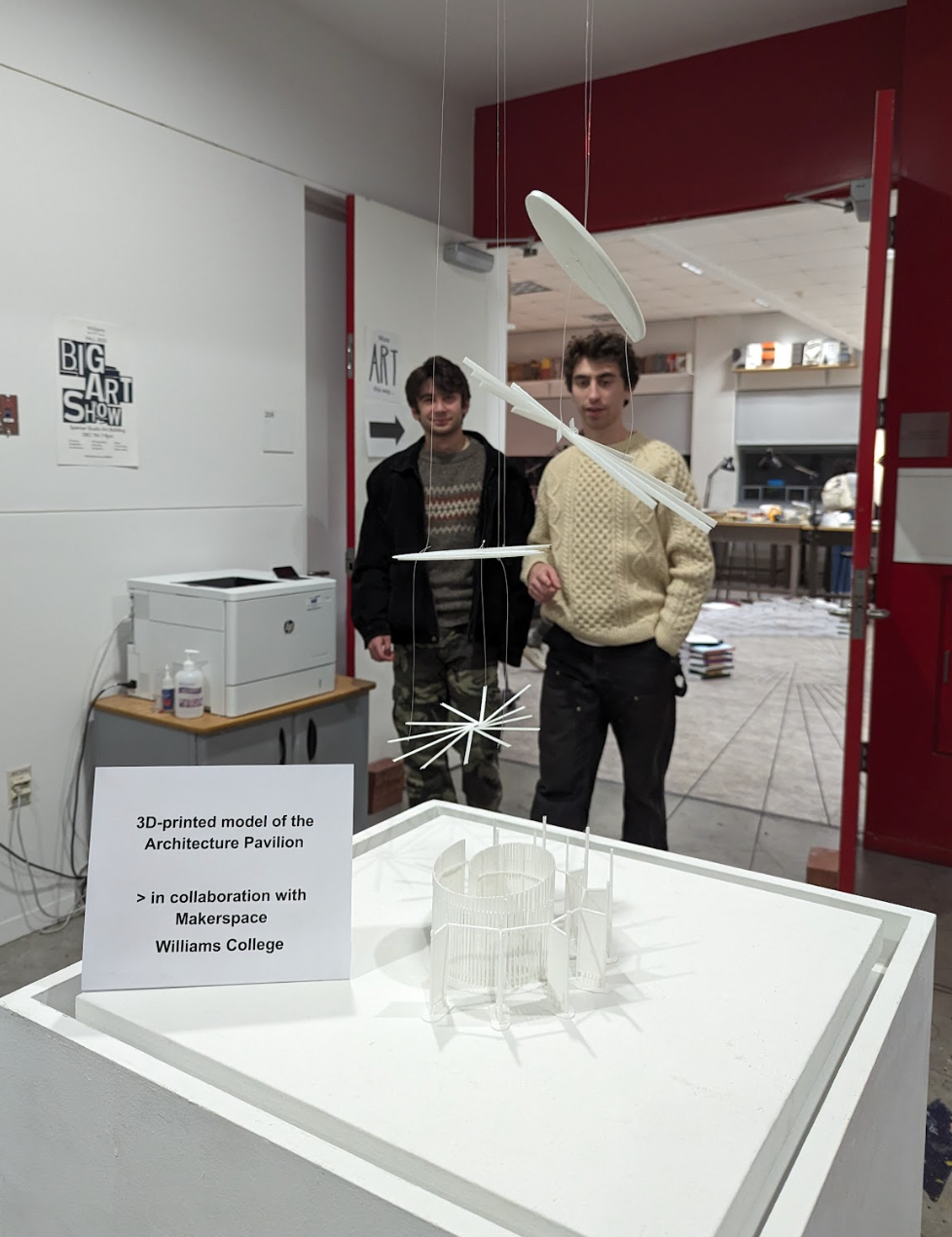
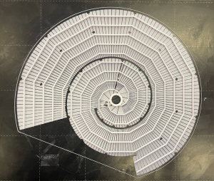
The Arts 314 exhibit in the Big Art Show
In my first Makerspace academic project, I jumped into the deep end. My role was to support Giuseppina Forte, the Assistant Professor of Architecture and Environmental Studies, and her students by preparing exhibition materials for the end-of-semester campus Big Art Show. I supported her two studio arts classes “ARTS 314 / ENVI 310 – Design for the Pluriverse: Architecture, Urban Design, and Difference” and “ENVI 316 / ARTS 316 – Governing Cities by Design: the Built Environment as a Technology of Space”. For ARTS 314, her students designed an architectural model of an outdoor community building, and for ARTS 316, they re-envisioned the Cole Avenue Rail Yard area of Williamstown into a river-side park. My role was to convert the students’ digital architectural designs into 3D-printed objects. What seemed straightforward quickly became a challenging—and amazing—learning experience filled with challenges and growth that I want to share.
Prototyping
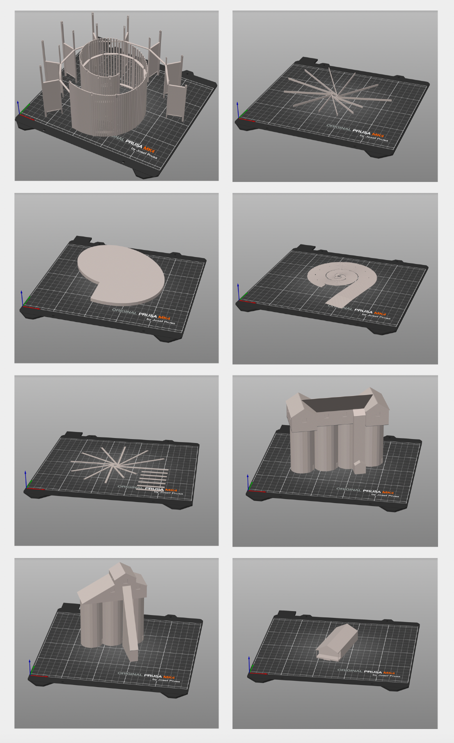
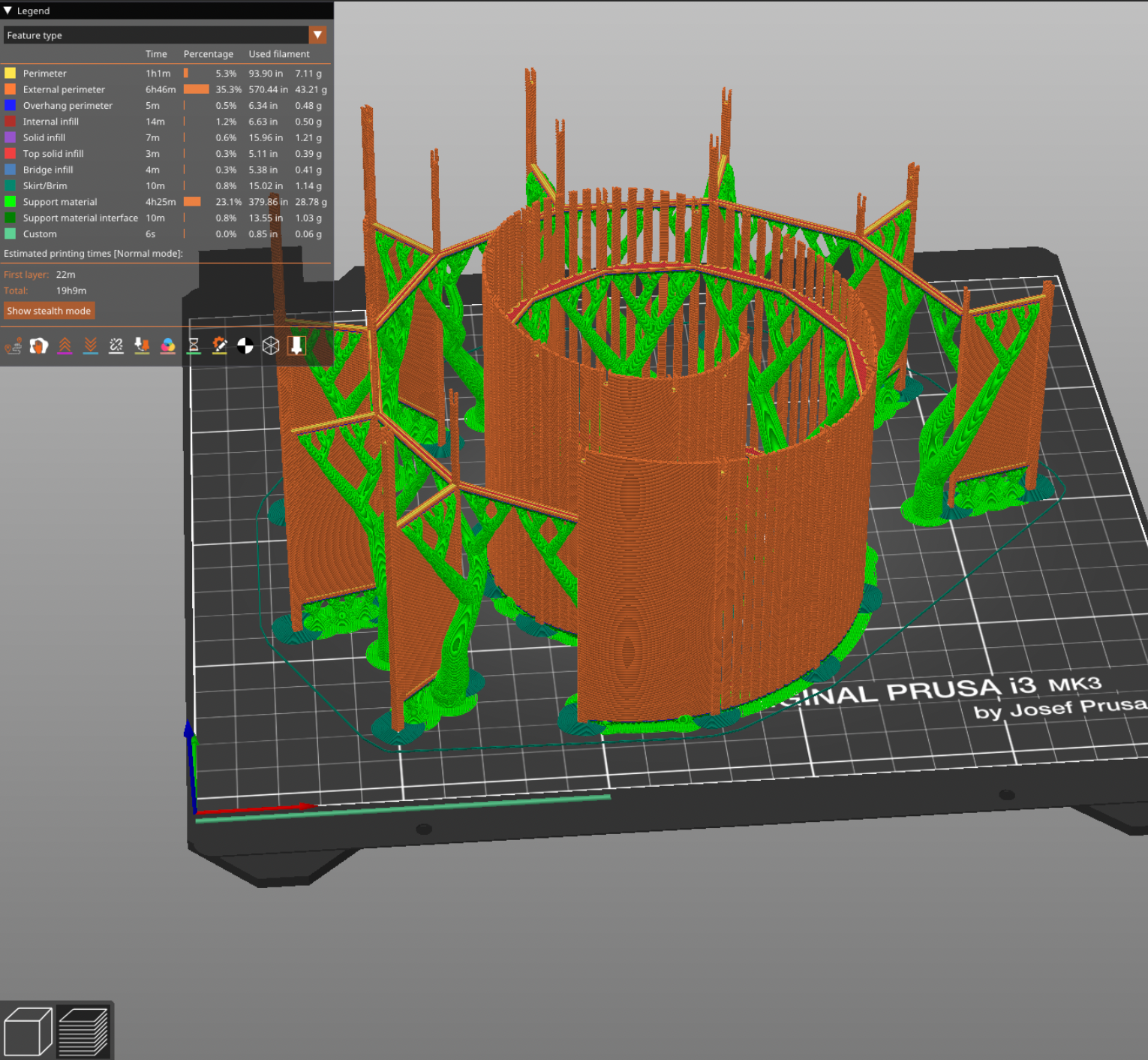
The first of many difficulties arose when I sliced, or readied, the models for the 3D printers. First, some files seemed to have problematic features deeper than the abilities of the FlashForge and Prusa slicer software repair algorithms. So, I spent some time learning MeshMixer and how to identify the Achilles heels of the models. In most cases, manually widening thin connections was sufficient. Second, some prints seemed impractical, if not entirely impossible. In some cases, these impractical features were easily removable without destroying the final product, like thin columns on B3. In others, features were inherent to the design, such as with A1, which posed a challenge for 3D printing due to its elevated, thin, and intricate spiral design. Finally, some prints, like B2, would just take an incredibly long time to print – up to 60 hours.

The models I would print. From top left to bottom right: A1, A2, A3, A4, A5, S1, S2, B1.
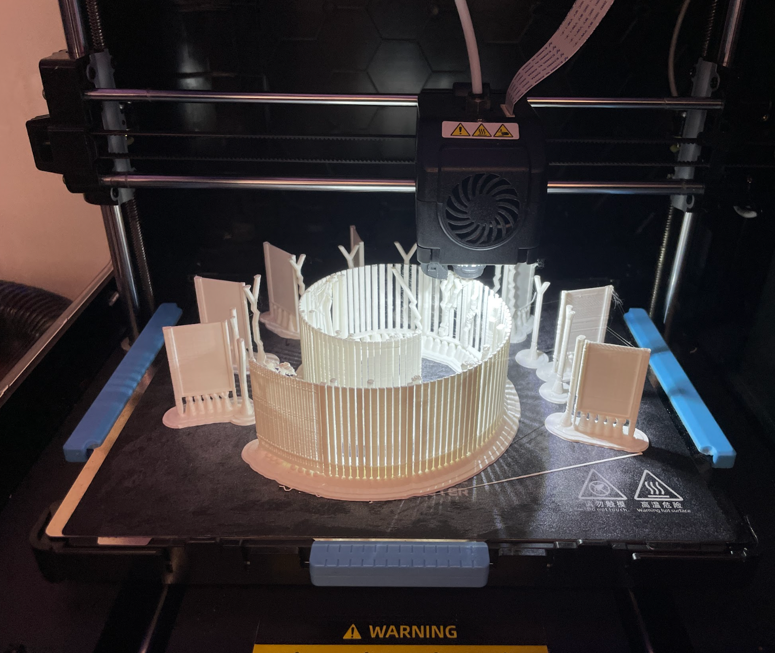
A prototype of A2
In a typical project, I would prototype each print and present them before starting any final prints. This helps to set expectations for what a 3D print looks like, how the pieces go together and allows me to get feedback on the prints. However, these prints proved particularly challenging to prototype for the above reasons. While I could get a couple of iterations of the simpler prints, many prints proved difficult to scale down due to their small and intricate details, and, in my mind, no prototype is worth 40 hours or 100 meters of filament because of the likelihood of repeated failed prints.
Crunch Time
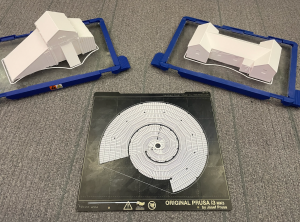
For prints with exposed, flat surfaces like A4, printing upside down provided a smoother finish and allowed the prints to peel off of the plate more consistently
However, dilly-dallying in this “half-prototyping” stage created a problem. Since I was hesitant to review an incomplete set with everyone, I mentally stayed in the prototyping phase, not starting any of the final prints. Instead, I spent this time optimizing the prints that I hadn’t been able to prototype. I ran tests to maximize the quality of the print while minimizing the filament used. While I can’t say that this time was wasted, since many of the optimizations helped me later, in hindsight, I wish that I had paid more attention to the time and started my final prints sooner, as I could have prevented much of the stress in the final time crunch.
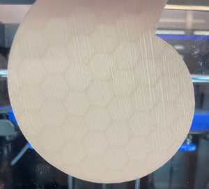
I found that I was able to go as low as 8% infill on solid prints before jeapordizing structural integrity.
The final week and a half of the project was a combination of epic stress and stellar production. It started with David Keiser-Clark, the Makerspace Program Manager, asking me if I thought it would be possible to finish and deliver the prints before the start of the show in nine days. I panicked. I had become so immersed in solving the technical issues that I had lost track of the delivery date. I sat down and figured out that the total printing time for this project would take ~240 hours. Had I immediately started two prints on the two working printers and ran them 24/7, the prints would have only finished three or four days before the deadline. I immediately put two prints on the printer and responded to David, cautiously telling him I thought I could finish them in time.

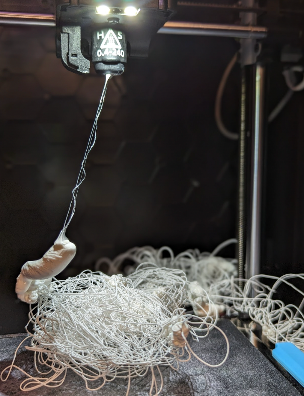
A spectacular failure of one of the prints
My estimates couldn’t have been more wrong. My first two prints should have been relatively quick and easy, but when I returned to collect them I was greeted by two spaghettified clumps of white PLA. I reran both prints, praying that they were flukes, but of course, they weren’t. Within 5 minutes, both prints had failed again. I did a 20-minute calibration of both printers and reran the prints: the print in the FlashForge was successful, but the Prusa failed again. Time was slipping away, and only one printer was operating reliably.
Removing Roadblocks

All four printers running smoothly!
I reached out to David and explained the issue. He helped me configure the two out-of-commission Dremel printers, which seemed to be my saving grace. However, I transferred my slices to the Dremel and found that many of the round prints were larger than the Dremel’s base plate. This, combined with the fact that the Dremels struggled with finer detail in test prints added to my stress. However, after examining the models, I found that I could cut the larger files into smaller pieces, print them, and then later assemble and permanently glue them together.
The final print of A2 and the tops of S1 and S2, unfortunately printed in different sizes.
Six days before the show we had four working printers. The Prusa had been fixed (twice) and was churning out the finer detailed prints. The FlashForge was working on a piece of the largest print, which I had cut down to 30 hours (from 48) by increasing the layer height to the maximum of 0.3mm (75% of the nozzle diameter). Both Dremels were printing the remaining pieces of the largest print and we had received permission to use the Science Shop’s Ultimaker for A1, which was the most challenging, longest-running, and most likely-to-fail print in the entire project. For a moment, it looked as if the project would be done comfortably in time, with several days of cushion to spare.

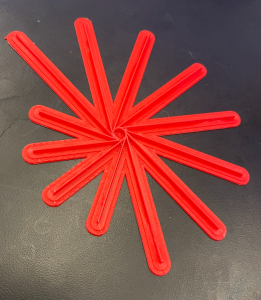
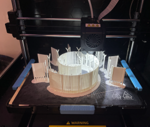
Using natural supports used less filament, took less time, and failed less than vertical supports
One day later the situation flipped on its head. The filament for the Ultimaker, ordered in advance, failed to arrive. Three prints in the Makerspace failed. The filament roll on the FlashForge got tangled and caused a jam, the Prusa had spaghettified, and one Dremel printed the house sans the roof. I was able to find and solve a problem within the Dremel slicer software and recalibrate the Prusa, but for now, the FlashForge was out of commission.
In hindsight, I had not anticipated the variance in scaling among different slicing softwares. The Dremel software defines its x-axis differently than the FlashForge software, which resulted in pieces that scaled poorly with the rest of the model.
A copy of A1 printing on the FlashForge 1 day before delivery.
Three days before the show, I had somehow managed to print A2, A3, A4, A5, B1, and B3. We fixed the Dremel and set the most structurally fragile and complicated print (A1) to run overnight on all four printers. This would be our last chance.
One day before the show, our final prints were completed: the Prusa and FlashForge succeeded, while both the Dremels failed. Of the two successful prints, the Prusa created a beautiful, highly detailed print. Unfortunately, I woke up with the flu and didn’t get to say goodbye to the prints, nor could I go to the Big Art Show. However, I got to see pictures and I was proud to support the students’ architectural work for the show, but, to me, the greatest value of this project was not in the prints themselves, but in the lessons that I learned and that I will take with me into my future work both in and out of the classroom. Specifically, I developed confidence in my ability to solve technical problems in a new medium while working under pressure and improved my capacities in project management.

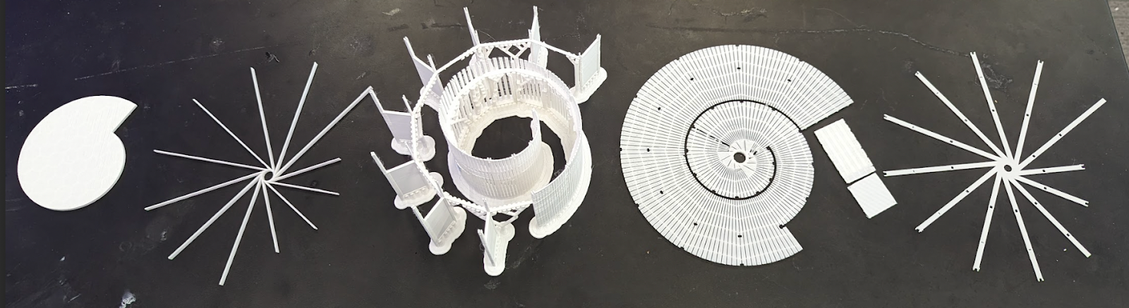
The final collection of pieces
Murphy’s Law
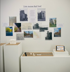
The Arts 316 exhibit in the Big Art Show
Murphy’s Law states that when something can go wrong, it will. Doubly so when you are under a time crunch. In hindsight, most of this pressure could have been avoided had I made an effort to timeline the project before the due date was imminent. When printing, you have to strike a balance between quality, material used, and time. Before the time crunch, I was trying to maximize quality and minimize the material used. However, the instant time became the driving factor, I swapped those priorities. All in all, it worked out, but if I had managed my time better I likely could have delivered just as good of a final product with less stress.
Post Mortem
During this project, I discovered how fragile 3D printers are. We had four printers in the Makerspace, and I had to do a total of eight mechanical fixes. At some points, I felt completely defeated. It seemed like every successful print was counterbalanced by an awful grinding sound or a jammed PLA feed. This was not the first time I had ever 3D printed, but it was my first time tinkering with 3D printers. Admittedly, at the start of the project, I was so scared of breaking something that I barely opened the side panel before asking for help. The silver lining of the printers breaking so often was that I had the opportunity to learn how to fix them. During the project, David took a few hours to show me around each printer, explaining how they work and where they usually fail. This paid itself off in dividends. By the end of the project, I was more than comfortable repairing every single printer we had and reached a point where I didn’t even have to tell David when they were broken, likely saving him more time than it took to help me figure out how all of them work. I’m excited to take this experience and apply it to my next faculty project in the Makerspace.