Imagine a classroom of 5th graders buzzing with excitement as their mousetrap-powered cars zoom across the floor, each tweaking their design to outrace the others – all while learning the physics of potential and kinetic energy. That’s the vision behind the Williams College Makerspace’s Sustainable STEM Learning Kits project, and this semester, I had the chance to dive in, redesign a car from scratch, and use statistical methods to optimize its performance. Spoiler: it involved a paintbrush, some copper wire, and a magazine holder: improvisation at its finest!

Dual mousetrap powered car
Background: Building on a Legacy of Learning
This project builds on the groundwork laid by the Makerspace, Williams College CLiA, and the Zilkha Center through the TIDE Grant initiative, which aimed to create sustainable, reusable STEM kits for under-resourced 5th and 6th grade classrooms. As detailed in this Makerspace blog, one of the main ideas for the stem kits is a model car assembled from sustainable, reusable materials with some 3D-printed printed parts to teach energy concepts, aligning with Next Generation Science Standards (NGSS). Previous Makerspace student workers Divine Uwimana ’27 and Alice Sore ’27 created an initial design that used a rubber band to power the car. My work involved building up on and enhancing this initial design and exploring other forms of potential energy that could be used to power the car.
My Journey: From Brainstorming to Rapid Prototyping

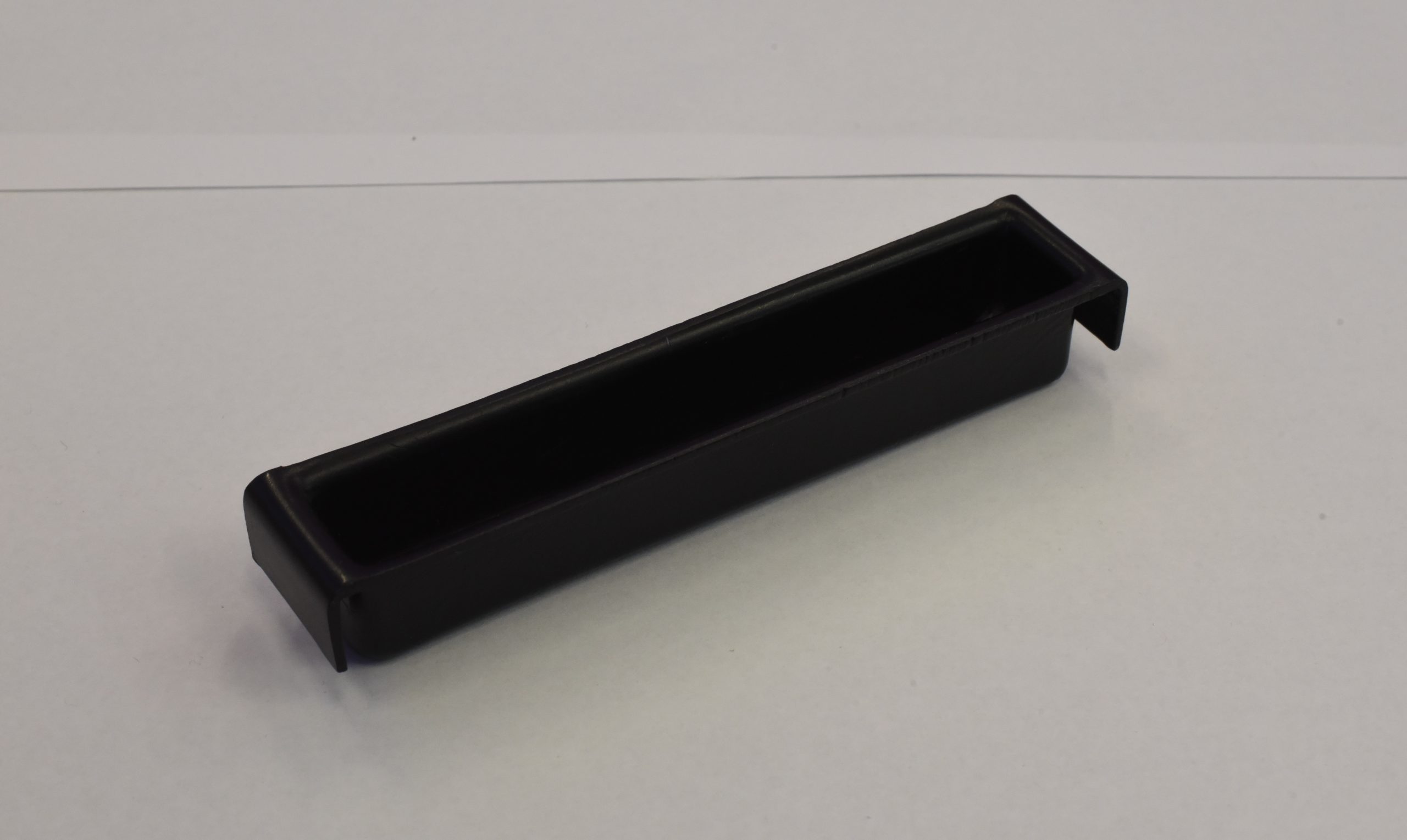
Mousetrap car parts

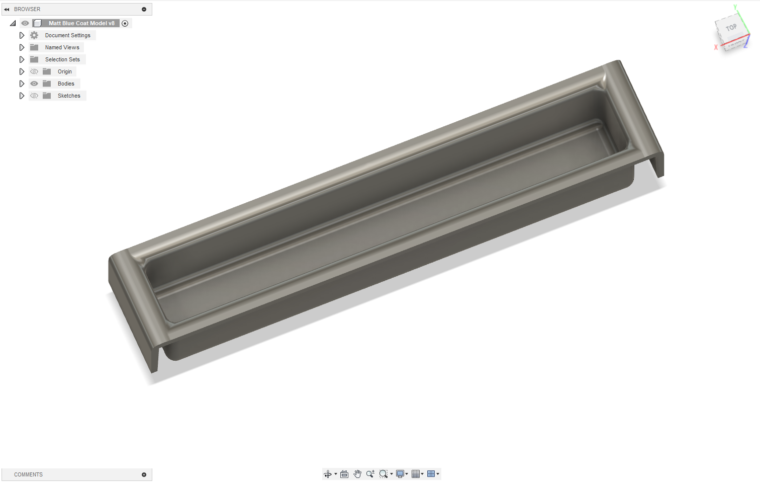
Fusion360 flywheel model
I kicked things off by meeting with Divine Uwimana to understand the project’s history and progress. Then, I teamed up with Izzie Tarantino for this joint endeavor, guided by Makerspace Program Manager David Keiser-Clark. We brainstormed energy sources for the car: elastic bands, flywheels, mousetraps, and motors. Izzie focused on elastic energy (expanding on the previous work by Divine and Alice) and modular designs, while I explored flywheels and mousetraps. I initially designed a flywheel with 8 ball bearings but decided to pivot to the mousetrap car for this semester, leveraging the existing car body as a starting point.
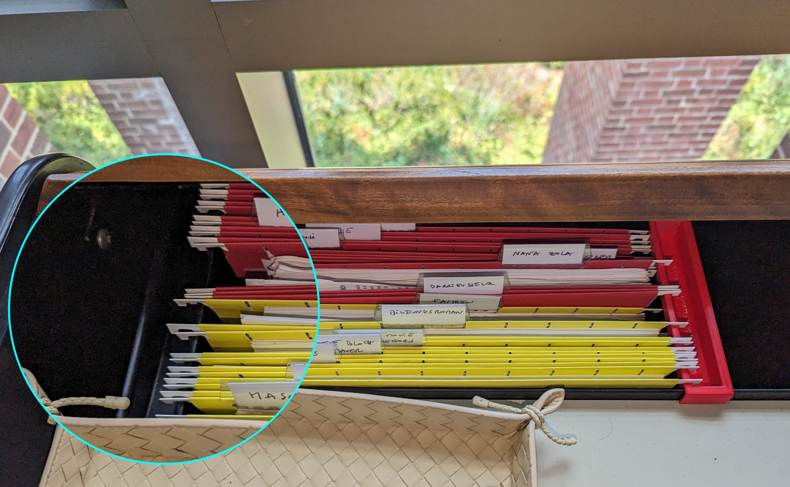
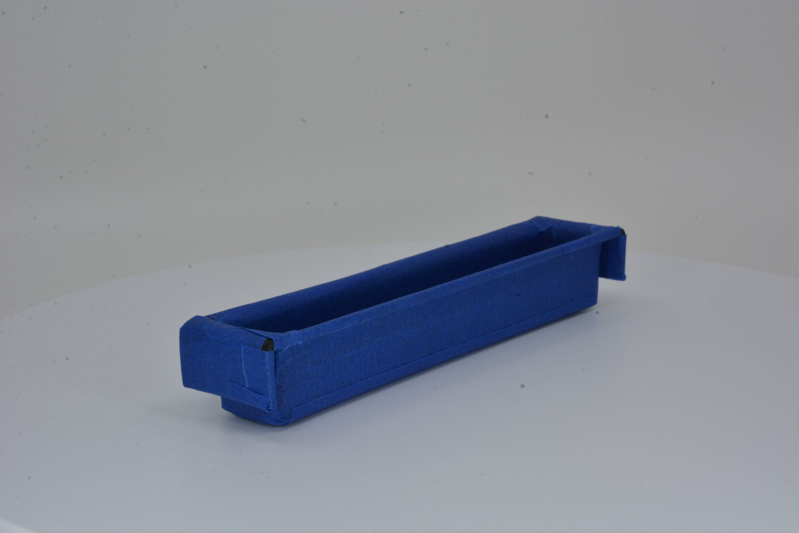
Having dabbled in Fusion 360 during a previous photogrammetry project, I saw this as a chance to deepen my skills. I tried modifying the prior design, but missing sketches made it tricky, so I started from scratch. The learning curve was steep; I relearned Fusion 360 mirroring and shape patterns, tackled advanced concepts like threading an axle, and spent hours troubleshooting. After printing the car body, I turned to rapid prototyping to test ideas without wasting resources. For instance, I used a paintbrush as a pole to connect the mousetrap to the axle with a string. I also experimented with connecting two mouse traps in series, designing a scalable system where one trap triggers the next. To test this trigger mechanism, I improvised with cardboard and copper wire, containing the setup in a magazine holder – Makerspace creativity at its best!

Mousetrap car rapid prototyping: testing trigger mechanism in makeshift compartment
Merging Design with Data: A Statistical Experiment
The project took an exciting turn when I realized it aligned perfectly with my Statistical Design of Experiments course (Stats 344). On one hand, I had an extracurricular project that was inherently experimental; on the other, I was learning statistical methods eager for application – a textbook case of supply meeting demand with zero opportunity cost! My Stats 344 team, consisting of Lee Mabhena ’25, Victor Cazabal ’25, and myself (26’), met at the Makerspace to run a 2^(7-4) fractional factorial experiment, testing seven factors: floor type (carpet vs. hard floor), wheel friction (high vs. low), string material (polyester vs. rubber band), number of mousetraps (one vs. two), pole length (short vs. long), car length (short vs. long), and added weight (0 g vs. 100 g). Our goal? Finding the combination that maximizes travel distance while identifying which factors matter most, enabling kids to experiment with configurations and compete.
After multiple experiments, including a central composite design, we pinpointed an optimal setup: 16.37 g weight and an 8.56-inch pole length, predicting a distance of 381.27 inches. Confirmatory runs (389.14, 380.88, and 350.55 inches) validated our model, and we confirmed that floor type, weight, number of mousetraps, and pole length significantly impact performance, while wheel friction, string material, and car length had less effect.

Factors affecting mousetrap car performance: floor type, pole length, and added weight
Reflections and Next Steps
This project was a game-changer for me. I sharpened my Fusion 360 skills, learned the value of rapid prototyping, and enjoyed my first Makerspace team collaboration with Izzie –our brainstorming sessions were a highlight! Looking ahead, I’d love to revisit the flywheel design as an energy source and eventually create a universal car body that supports multiple energy sources, like a “universal adapter” for elastic, flywheel, or mousetrap power. This would give students even more ways to explore physics while fostering creativity and competition. For now, I’m thrilled to have contributed to a project that empowers young learners and bridges classroom learning with hands-on innovation, helping students see science not as abstract equations, but as something they can build, test, and improve.