Last spring semester, the Makerspace @ Williams College pivoted to focus on academic projects that support teaching and learning goals; previously, this focus had been an aspirational goal. The Makerspace Program Manager, David Keiser-Clark, and his team of amazing student workers, now support a dozen interdisciplinary academic and campus projects at a time. A quarter of these projects support sustainability, or specifically the Zero Waste Action Plan, including: (1) a three-college collaboration to create an eco-friendly deterrent for Japanese Beetles in our community garden; (2) a prototype to upcycle plastic bottles into 3D printer filament; and (3) a set of laser engraved wood signs, sustainably harvested from Hopkins Forest, for a Stockbridge-Munsee led garden video and audio tour at the Mission House in Stockbridge, MA. Below, you’ll find a brief spotlight on each project, and possible ways we might build on these initial efforts.
E4 Bug Off Team Project : Mitigating Japanese Beetle Damage
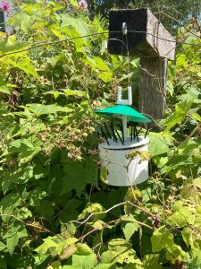
E4 Bug Off Team Project, installed in the Williams College Community Garden
The E4 Bug Off Team is a collaborative environmental project between engineering students from Harvey Mudd and Pomona Colleges, and students working with the Williams College Makerspace and Zilkha Center. The engineering students researched and developed a prototype that would safely repel Japanese beetles to hopefully stop them from defoliating raspberry bushes in the Williams College Community Garden. The Makerspace used 3D printers to create the parts and subsequently assembled the model. Zilkha Center interns then deployed the model in the gardens. The device is designed to be low-maintenance and only needs the reservoir filled weekly with 100% peppermint essential oil. Japanese beetles, in addition to other bugs and mammals, dislike the smell of the mint family, and the concentrated peppermint essential oil diffuses into the air via permeable wicks that extend from the reservoir tank.
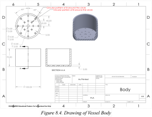
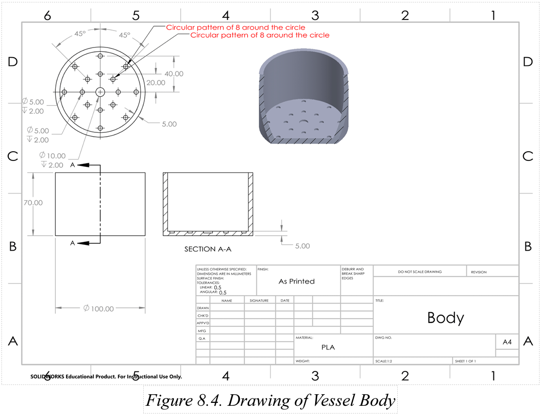
One of five engineering diagrams from the 30-page E4 Bug Off Team Project.
The initial model was installed in the garden in July 2022, at the tail end of the raspberry season, and immediately leaked. This spring (2023), the Makerspace re-printed the reservoir tank with a higher density (50% solid as compared to 15%), tested the model and, after 24 hours, found it to be 100% water-tight. This second model was introduced into the garden with mixed results: the functional model performs as intended, but the impact is difficult to measure without a control plot or method of measuring beetle activity this year.
In addition to recording measurements of a control plot, additional steps to increase effectiveness could include fabricating additional models to better saturate the air within the berry patch or returning the project to the engineering team for design modifications. The final version would be printed with ASA filament, which is physically stronger and UV/moisture resistant, as compared to PLA or ABS filaments.
To learn more about this project, read this blog post by Makerspace student worker Leah Williams.
Contributors: Harvey Mudd College (Students: Javier Perez, Linna Cubbage, Eli Schwarz, Stephanie Huang; Professors Steven Santana and TJ Tsai), Pomona College (Student: Betsy Ding), Zilkha Center (Students: Martha Carlson, Evan Chester, Sabrina Antrosio; Staff: Tanja Srebotnjak, Mike Evans, Christine Seibert) and Makerspace (Student: Leah Williams; Staff: David Keiser-Clark)
Polyformer: Sustainable 3D Printing at Williams College
While completing a month-long Zero Waste Internship at the Zilkha Center (through the ’68 Career Center’s career exploration Winter Study course), Camily Hidalgo pitched building a machine to convert waste plastic into usable 3D printer filament. The project aligns with the Williams College Zero Waste Action Plan, which is based on the sustainability strategy in the Williams College Strategic Plan. She envisioned this as being a collaborative effort between the Williams College Zilkha Center and the Makerspace.
After researching several options, she selected the Polyformer because it is an open-source (publicly accessible) project that seeks to create a DIY kit, composed of standard and commonly found parts, able to convert and upcycle plastic bottles (waste) into usable 3D printer filament. This project was launched in May 2022 and has quickly amassed more than 4,000 people who follow and/or contribute to the project (on Discord), while a core group of dedicated volunteers develop the project.

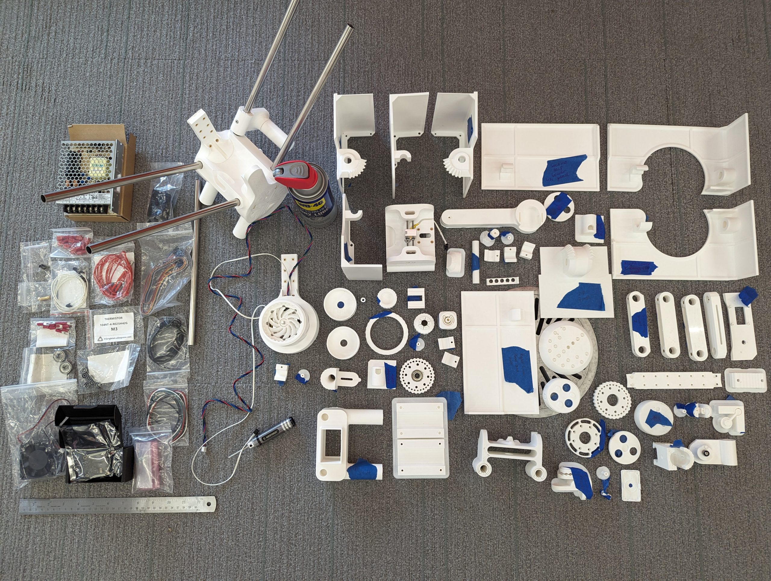
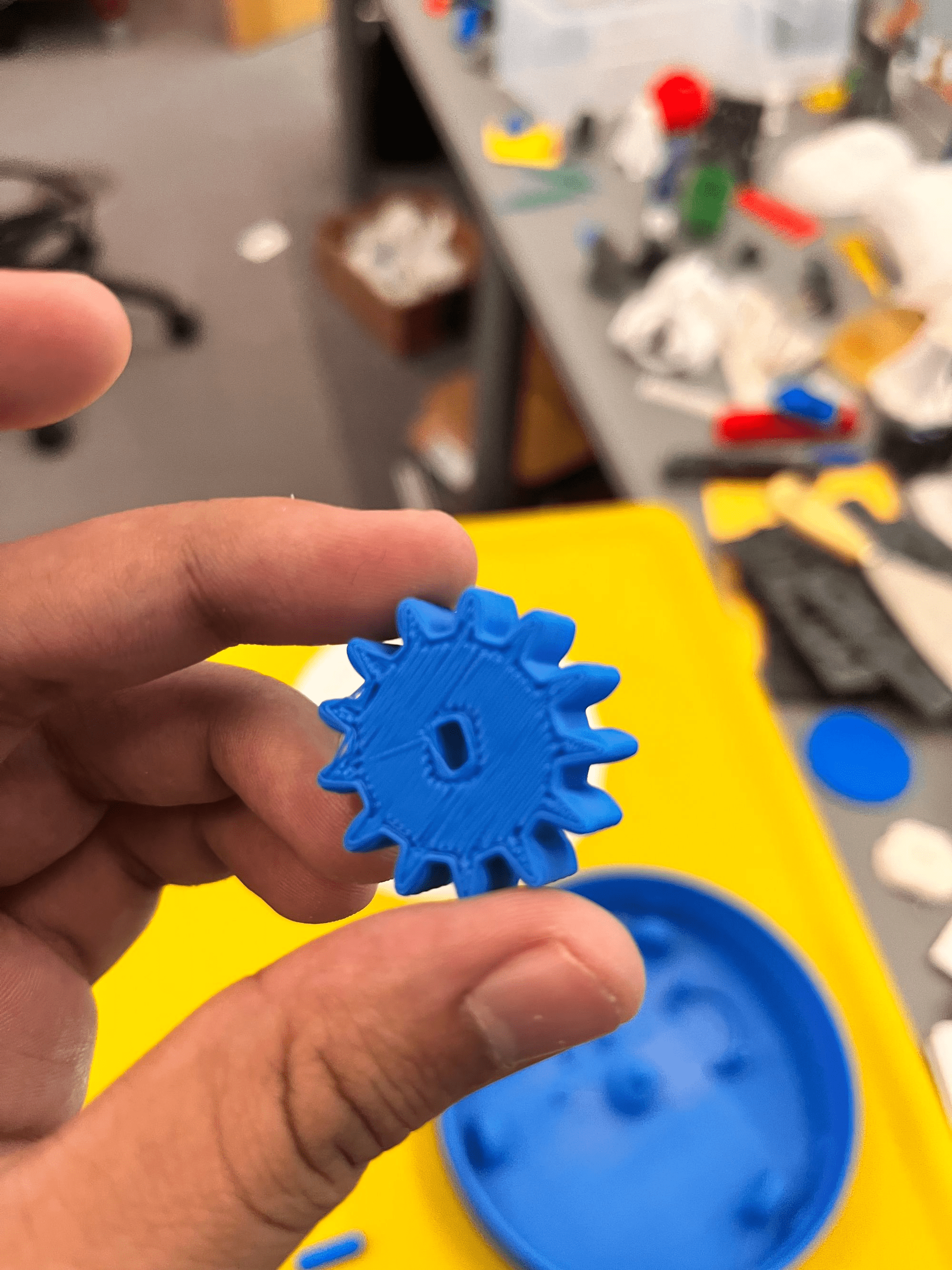
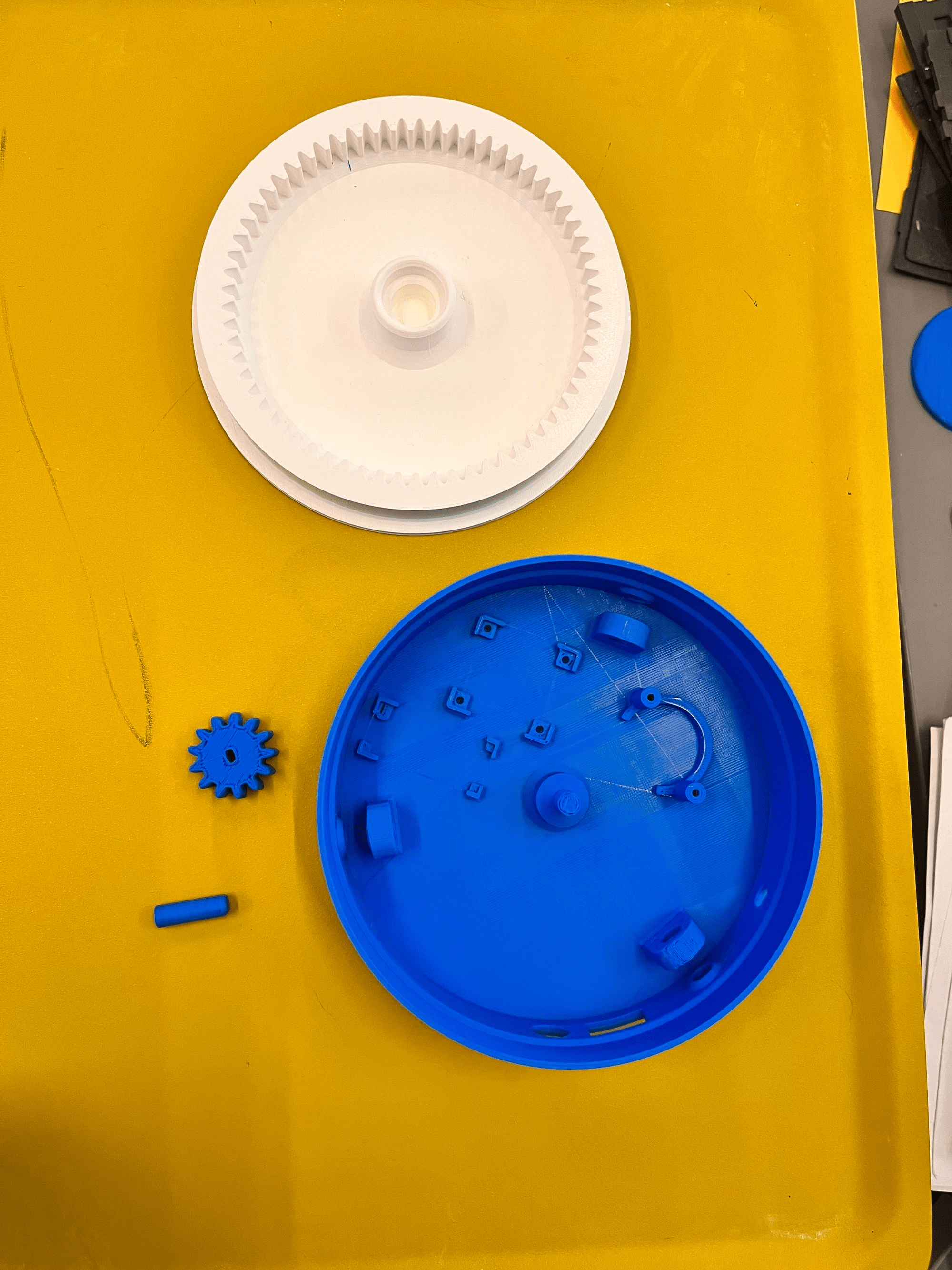
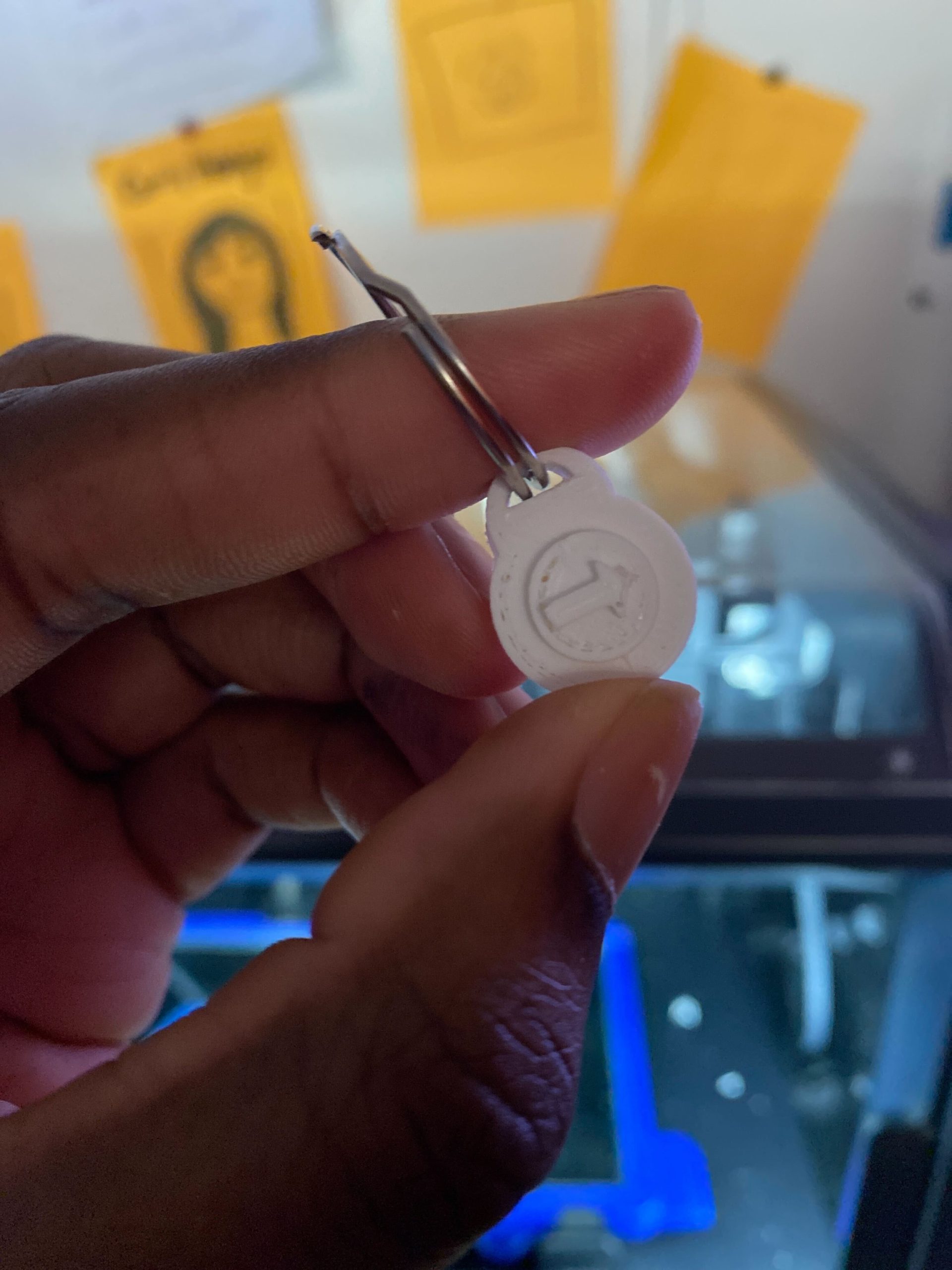
Many of the 78 printed parts that will be assembled into the Polyformer.
The intended outcome is to build a machine, based on standardized specifications, that effectively slices a water bottle into a half-inch wide ribbon, and then feeds that ribbon through a heated funnel, called a hot-end, to extrude it as 1.75mm PET filament. Camily seeks to create a working prototype to demonstrate our ability to disrupt our plastic waste stream and upcycle that into usable 3D printer filament. Approximately 40 bottles are required to create a standard 1 kg roll of filament, (enough to print 6 of the aforementioned beetle devices!). This project seeks to raise awareness that we can both reduce the quantity of waste that the college ships offsite while using that waste to create new filament and thereby purchase less of that virgin material from China. Upcycling waste can reduce the environmental impacts associated with the extraction of raw materials and product manufacturing as well as the significant carbon footprint associated with shipping those products to us from the other side of the globe.
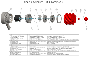
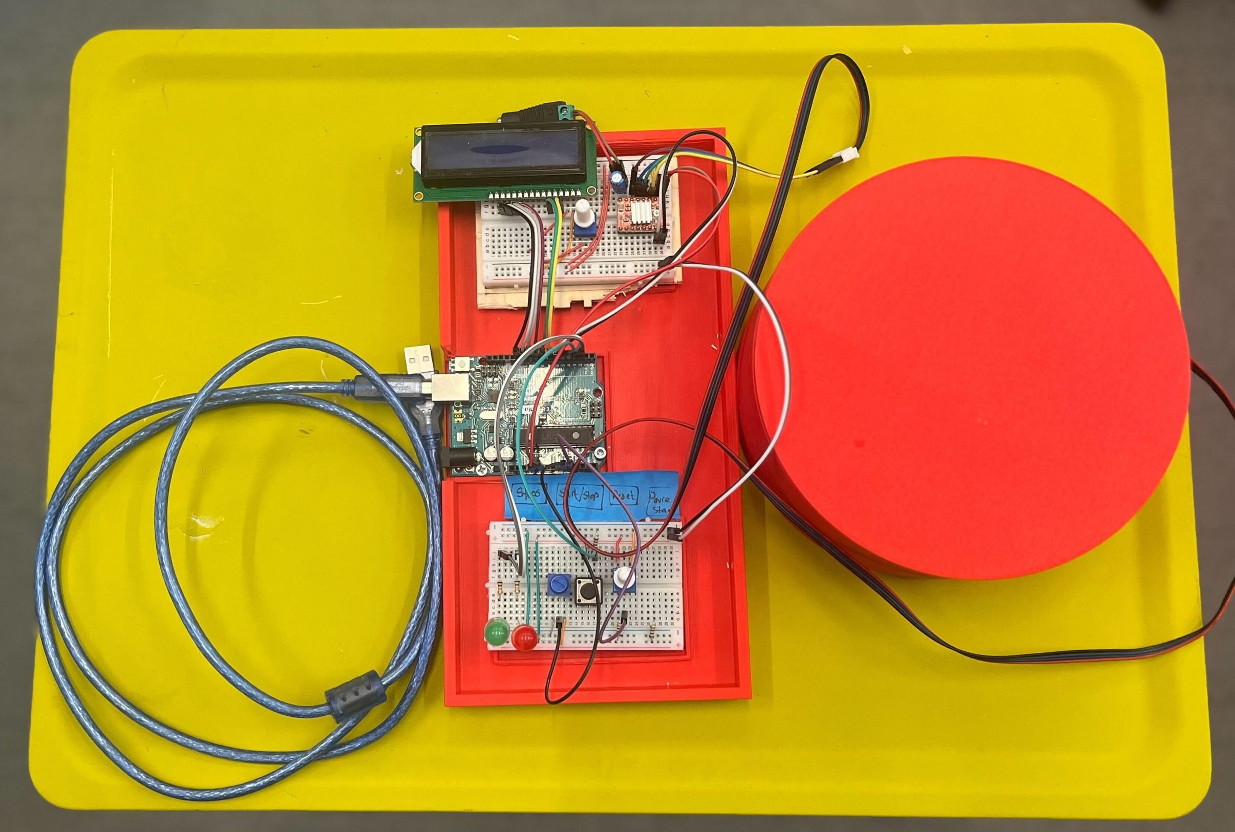
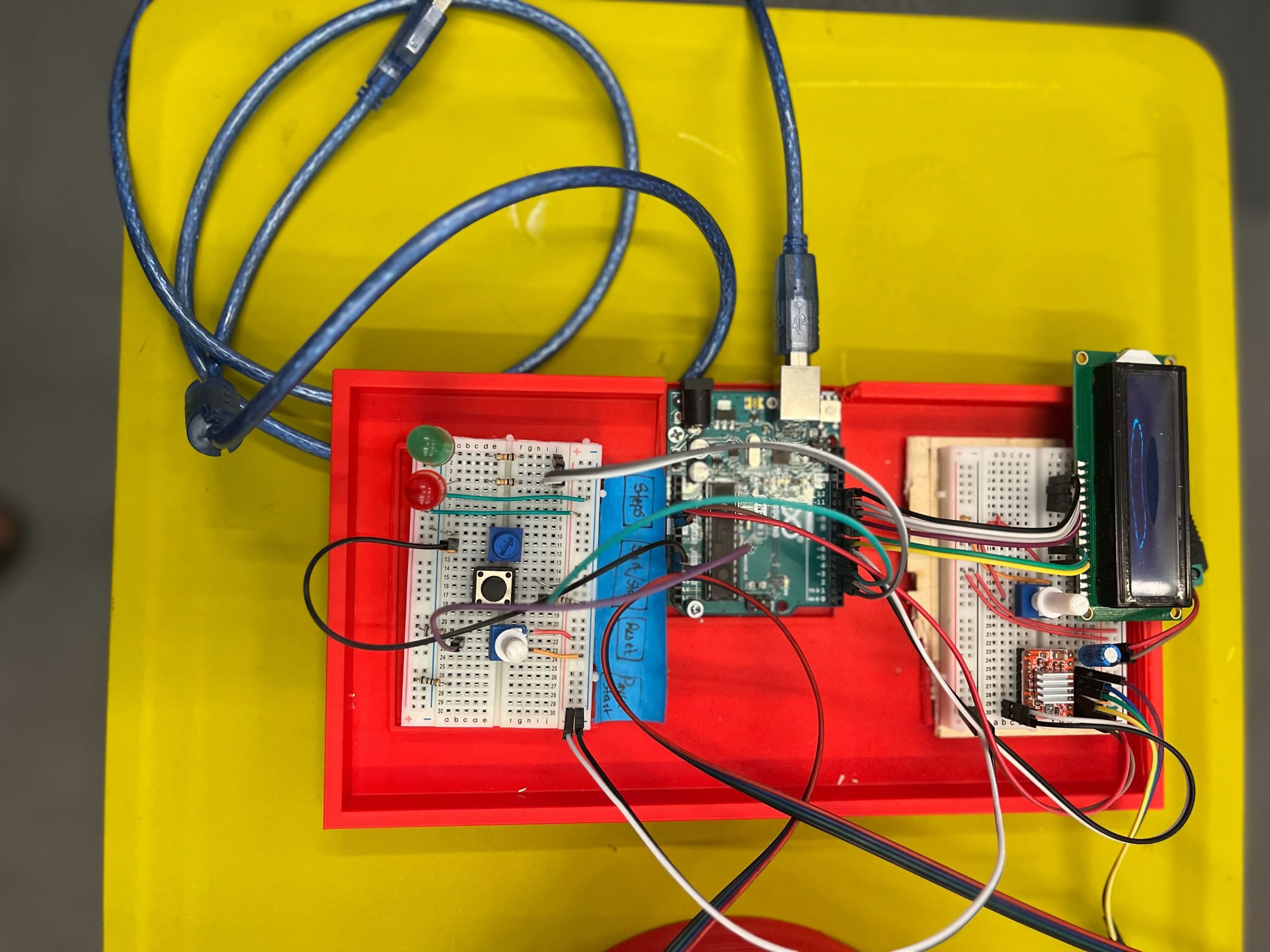
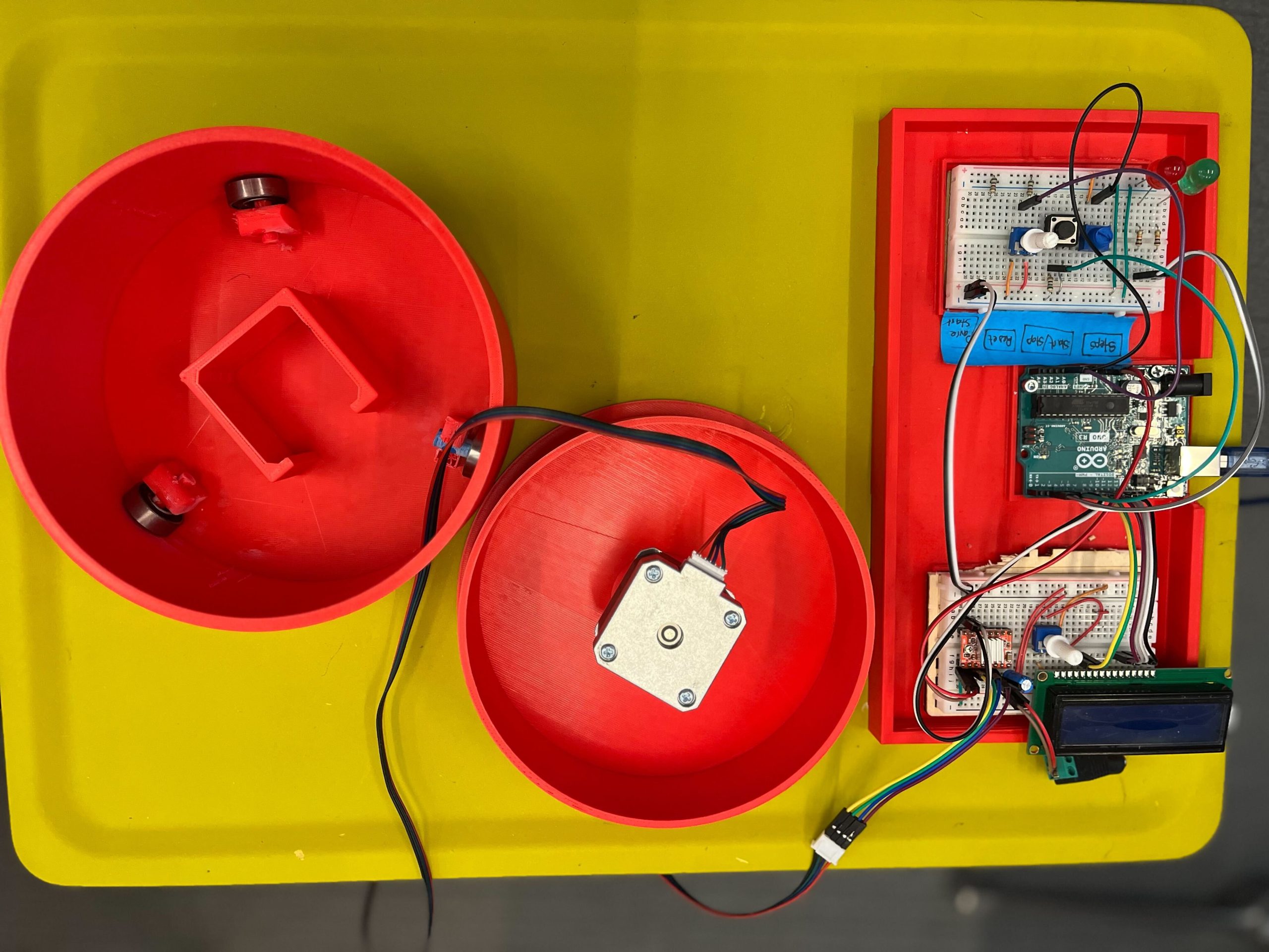
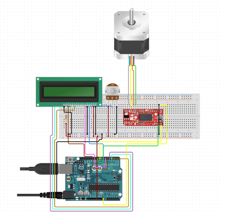
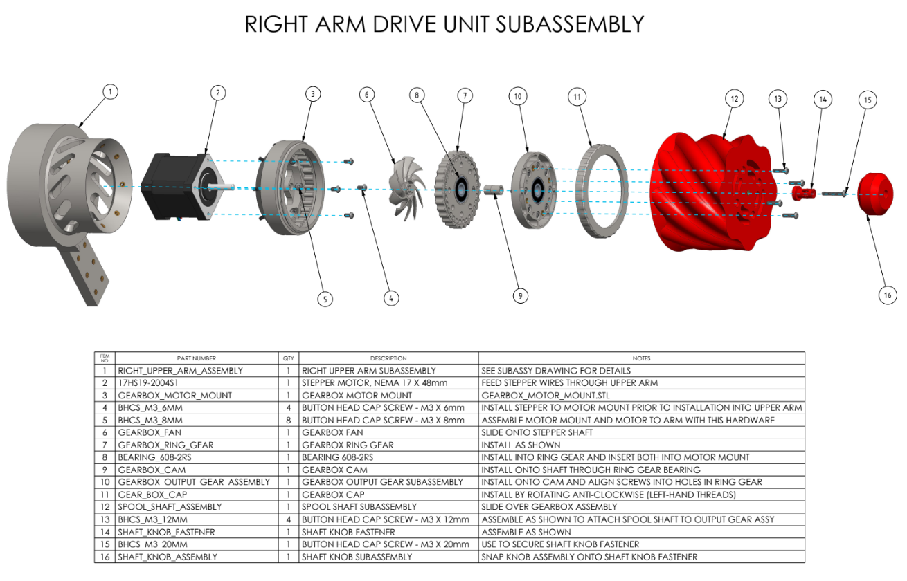
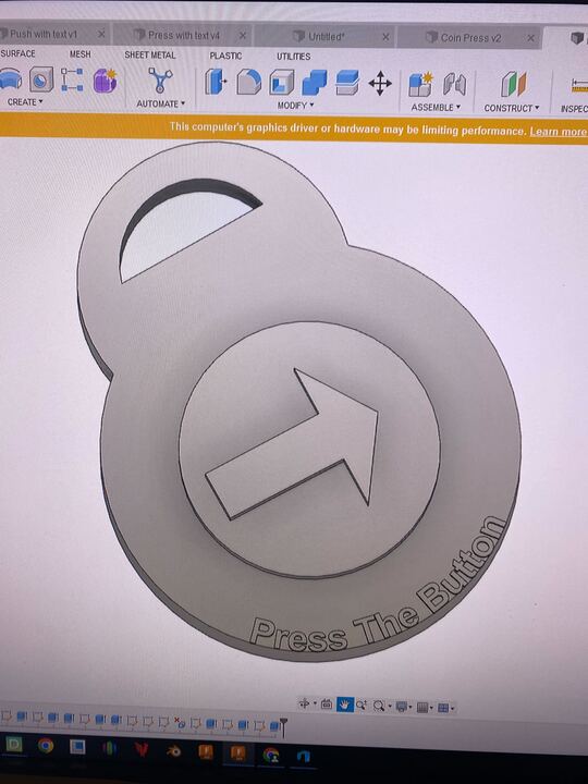
Polyformer diagram for building the “Right Arm Drive Unit Subassembly.”
Camily Hidalgo notes that this project is complicated because the design is constantly being improved. Additionally, it requires 3D printing 78 individual parts and then assembling those with a kit of sourced materials that includes a circuit board, LCD screen, a volcano heater block and 0.4 mm hot end, a stepper motor, stainless steel tubing, bearings, neodymium magnets, lots of wires, and lots of metal fasteners.
This project began last spring semester and, as of this summer, all 78 parts have been locally printed. Assembly has begun, and will be completed during the fall semester, followed by actual testing under a science lab exhaust hood to safely capture antimony, a VOC released when PET reaches its melting point.
To learn more about this project, read this blog post by Makerspace student worker Camily Hidalgo.
Contributors: Zilkha Center (Student: Camily Hidalgo; Staff: Tanja Srebotnjak, Mike Evans, Christine Seibert), Makerspace (Students: Camily Hidalgo, Milton Vento; Staff: David Keiser-Clark), Chemistry (Professors: Chris and Sarah Goh; Staff: Gisela Demant, Jay Racela)
Laser Engraving: Stockbridge-Munsee Garden Video and Audio Tour

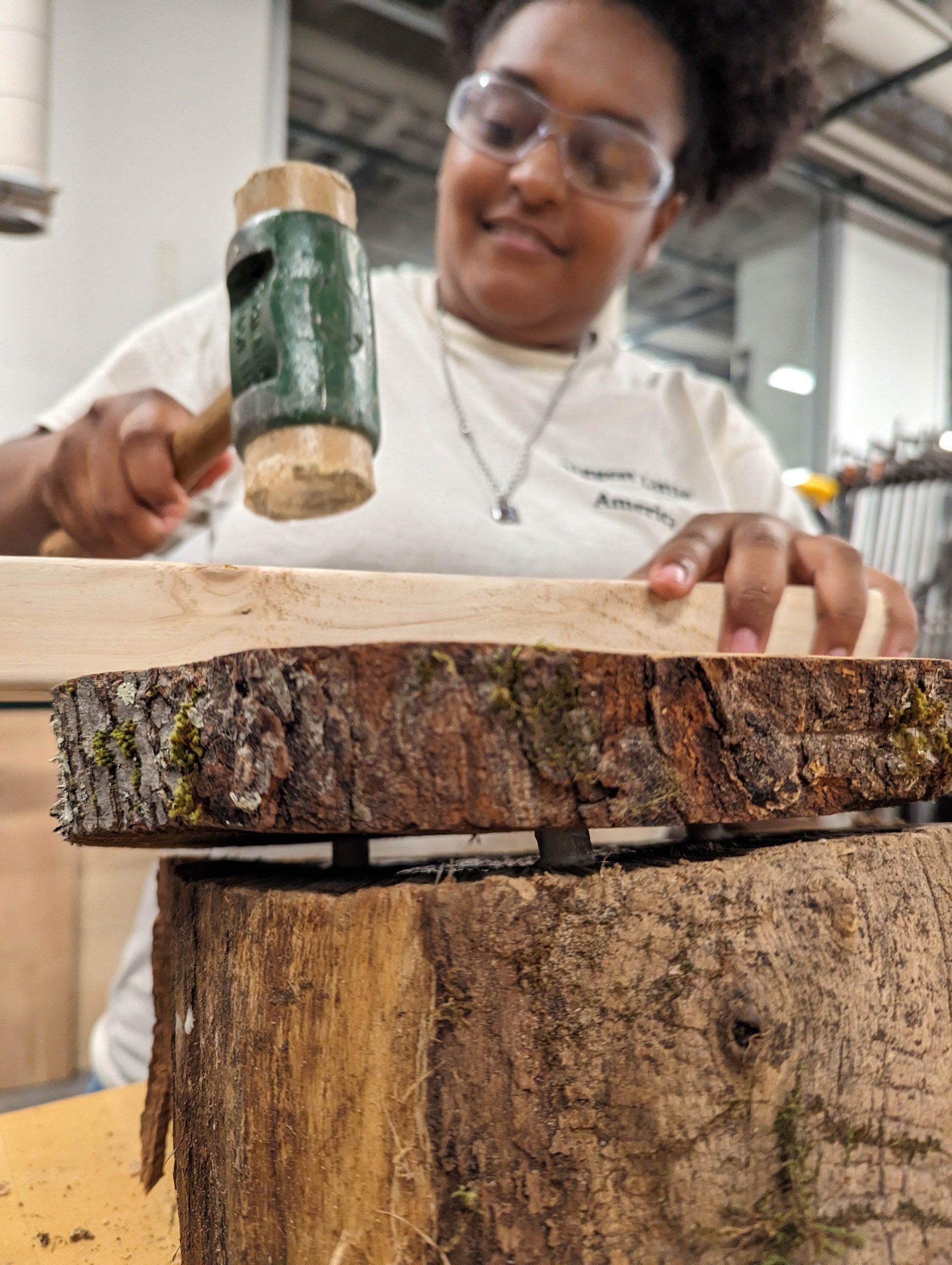
Yoheidy Feliz connecting a red maple slab to a slanted locust base, with dowels and wood glue.
The Stockbridge-Munsee Community Historic Preservation Office summer intern, Yoheidy Feliz, reached out to the Zilkha Center for help with creating locally sourced wooden signs for a permanent video and audio tour at the Stockbridge-Munsee Garden in Stockbridge, MA. She received a dozen sugar maple and red maple discs, plus locust wedges, all sustainably harvested from already fallen trees in the Williams College Hopkins Forest.
Yoheidy approached the Makerspace and, in collaboration with expertise and tools from the Science Shop, learned how to use an industrial laser engraving machine to etch a welcome sign with QR code, as well as multiple audio guide messages, onto sanded wooden discs. She attached these discs to sloped wooden bases (“wedges”) using woodworking dowel joinery, wood glue and a mallet, and then applied a natural, non-toxic preservative coating of Walrus-brand tung oil.
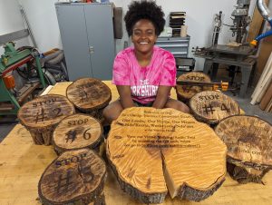
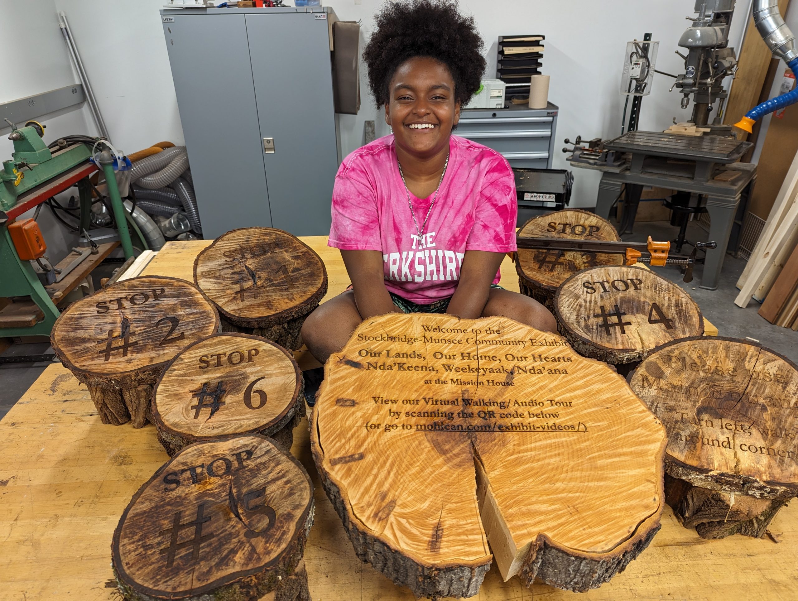
Yoheidy sits with her series of laser engraved wood slabs. She later added a laser engraved metal QR code label that directs users to the hosted video tour.
The day after completing all of this work, she installed these at the Mission House garden, and then created these stunning video and audio tours to guide local and remote viewers through the gardens.
To learn more about this project, please be on the lookout for an upcoming Makerspace guest blog post by Yoheidy Feliz.
Contributors: Stockbridge-Munsee Community Historic Preservation Office (Staff: Bonney Hartley, Historic Preservation Manager; Student: Yoheidy Feliz), Science Shop (Staff: Jason Mativi, Michael Taylor), CES & Zilkha Center (Staff: Drew Jones, Christine Seibert), Makerspace (Staff: David Keiser-Clark)
Cloning the Last of its Kind
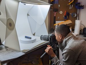
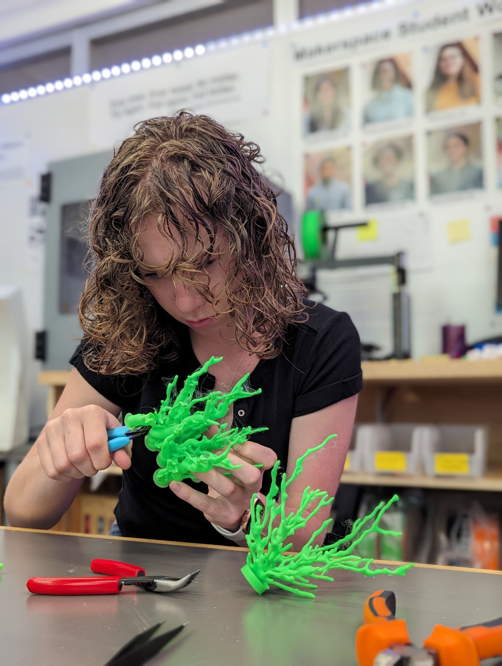
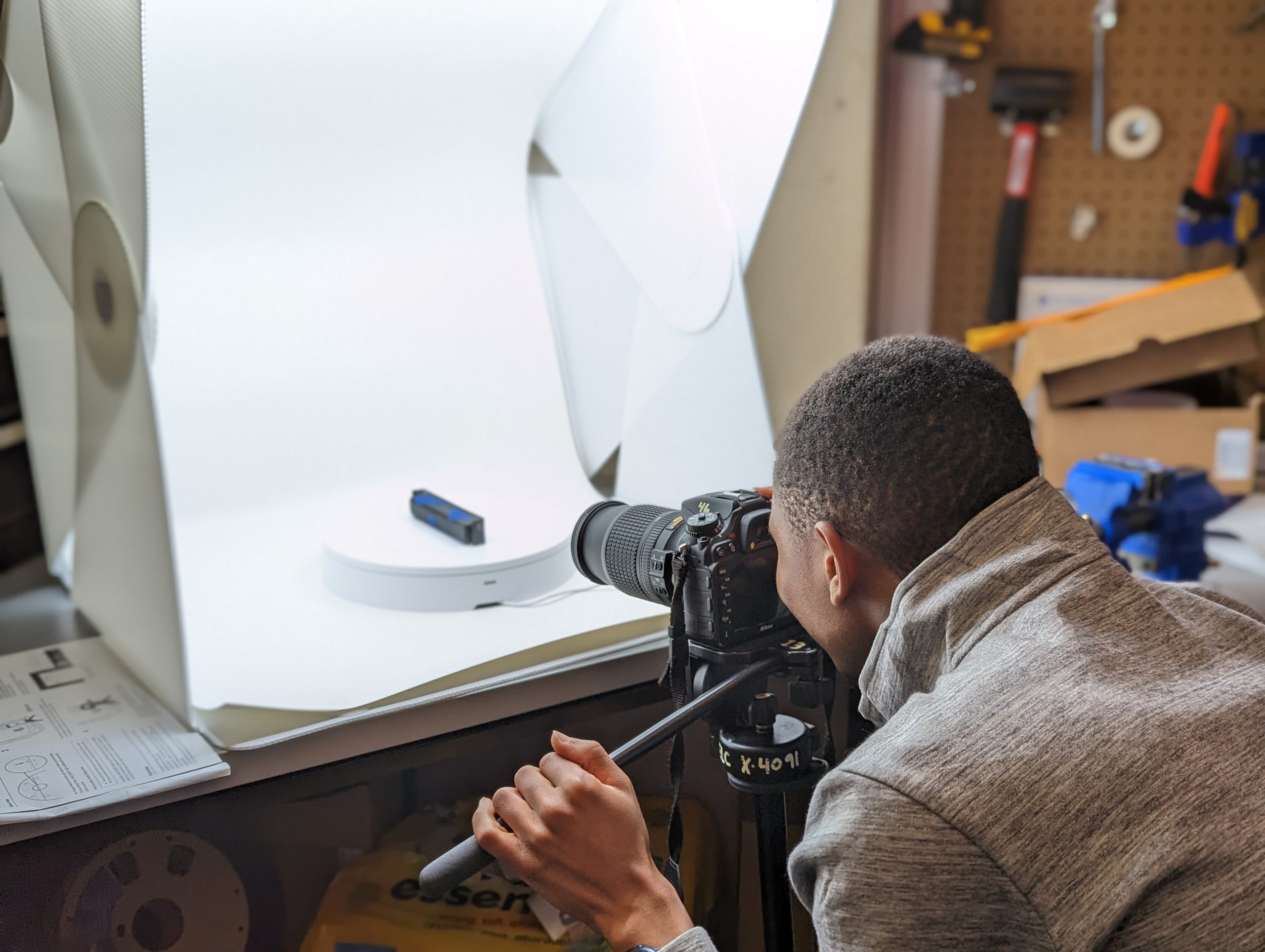
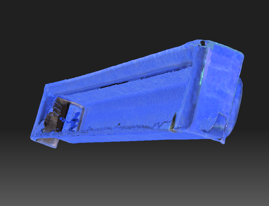
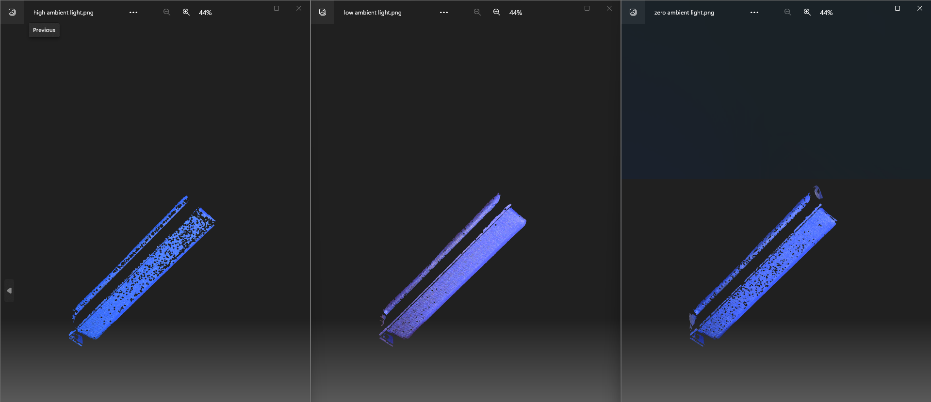
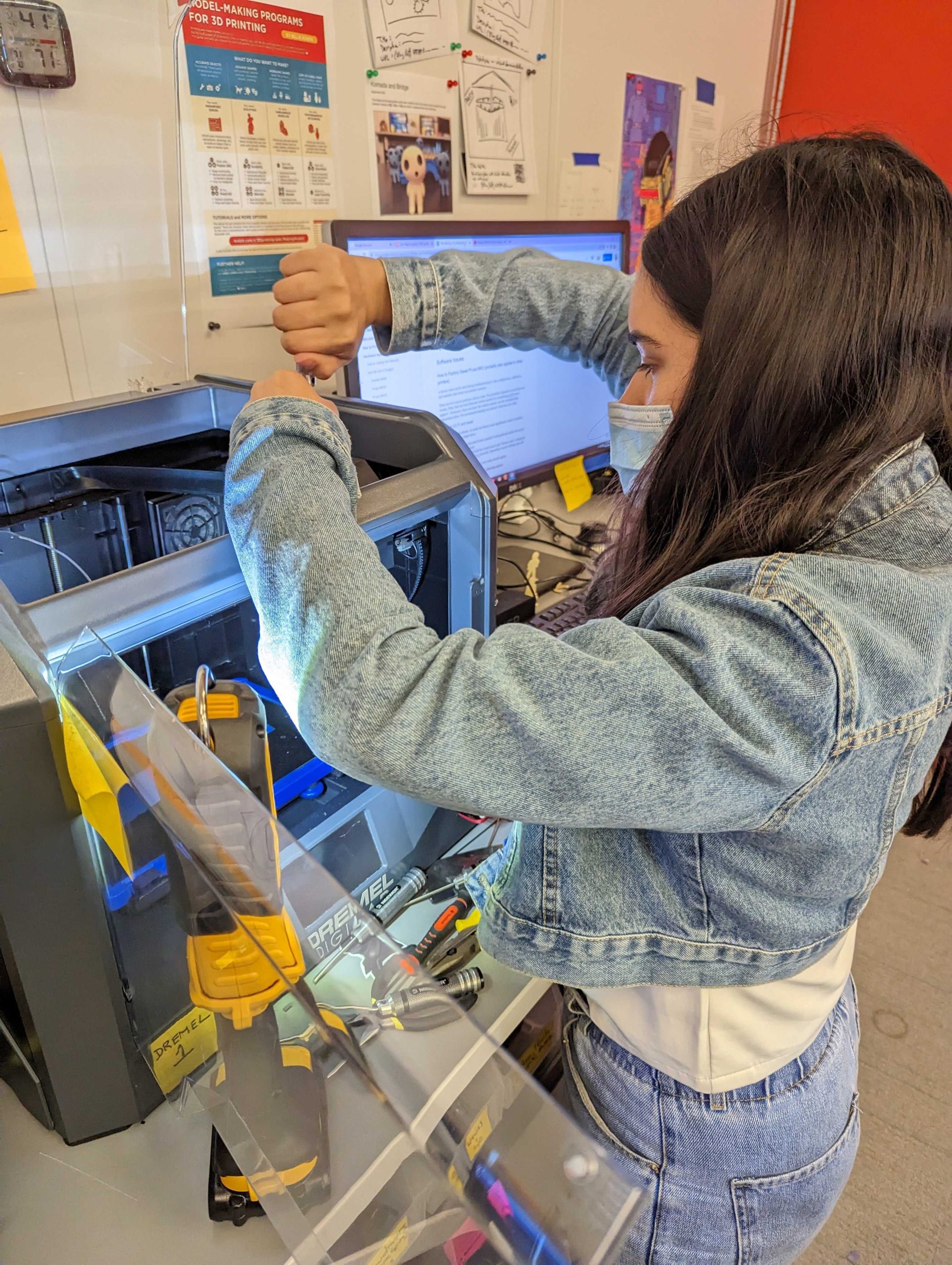
Milton Vento ‘26 using photogrammetry to create a 3D object
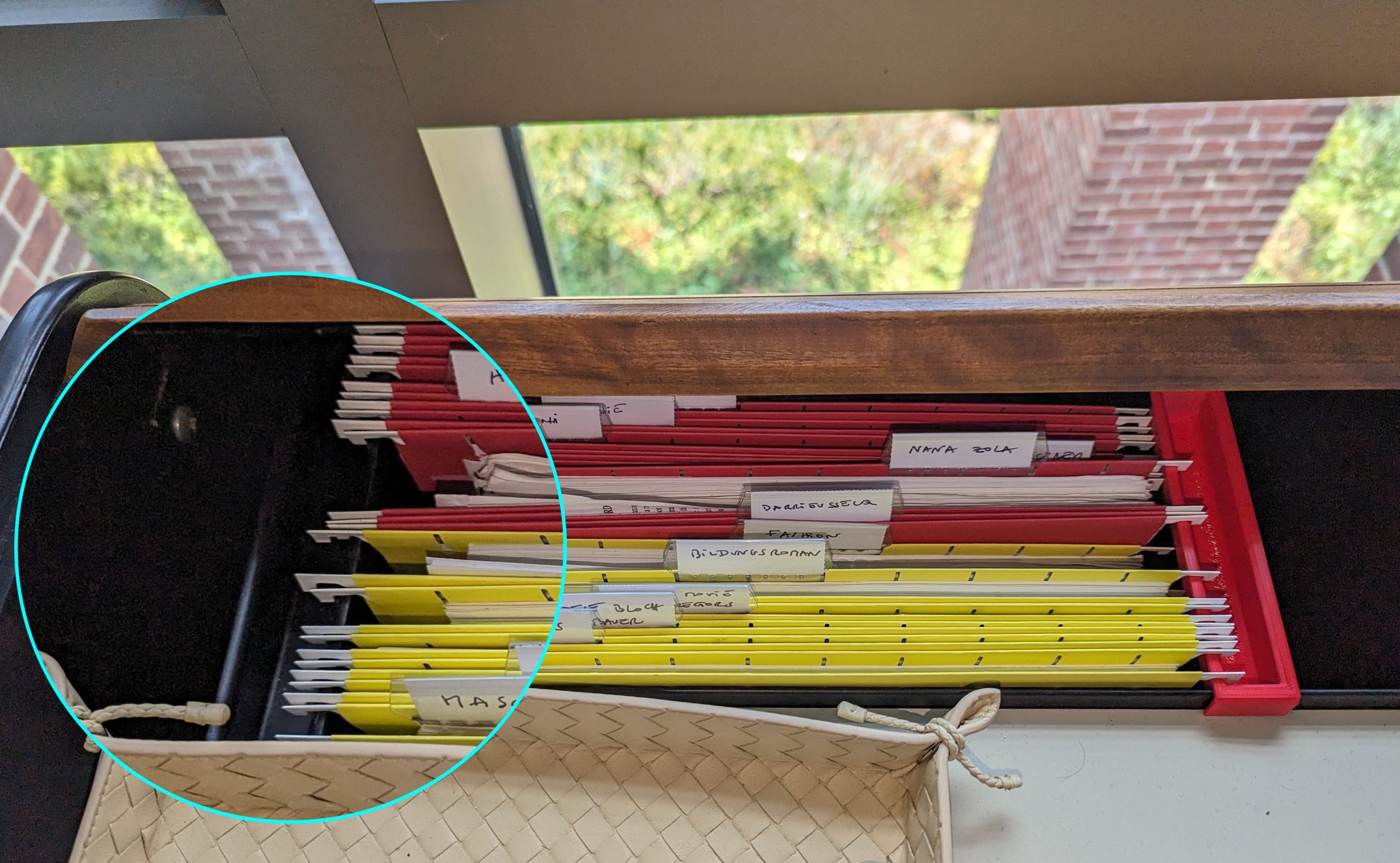
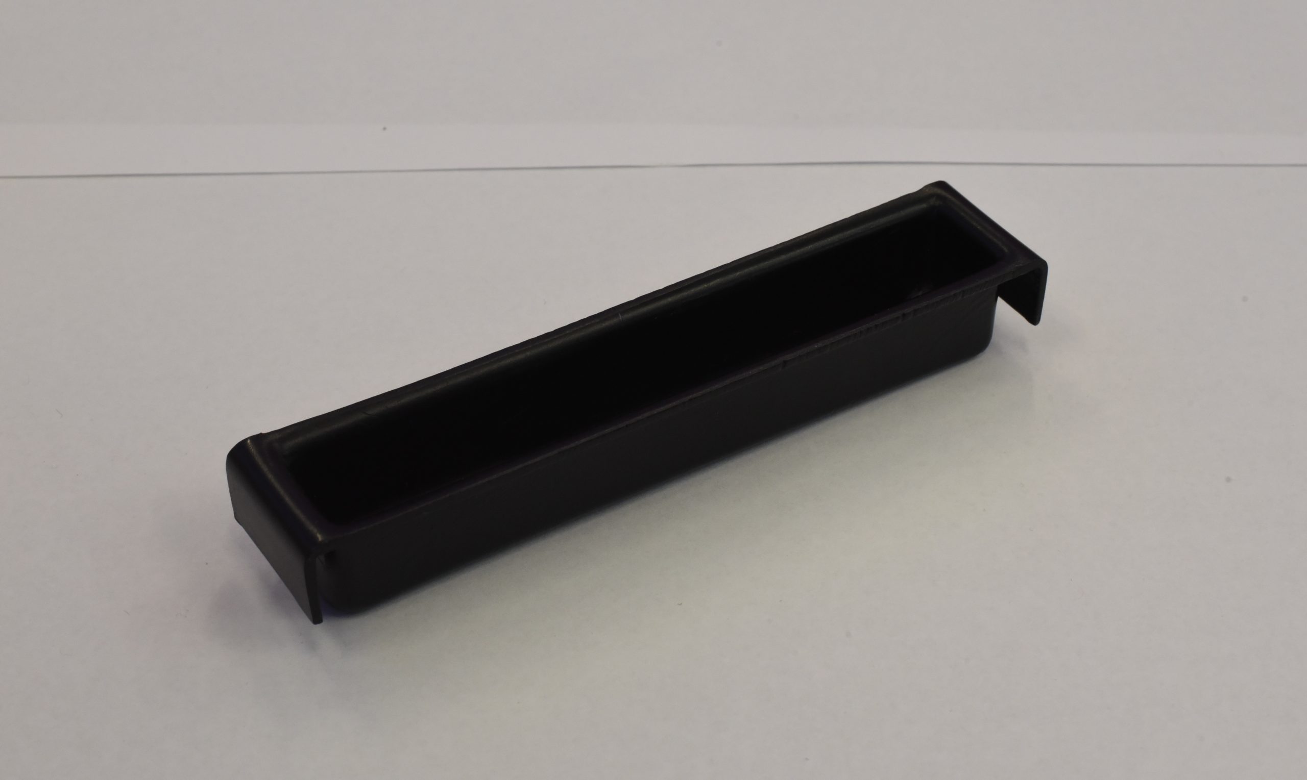
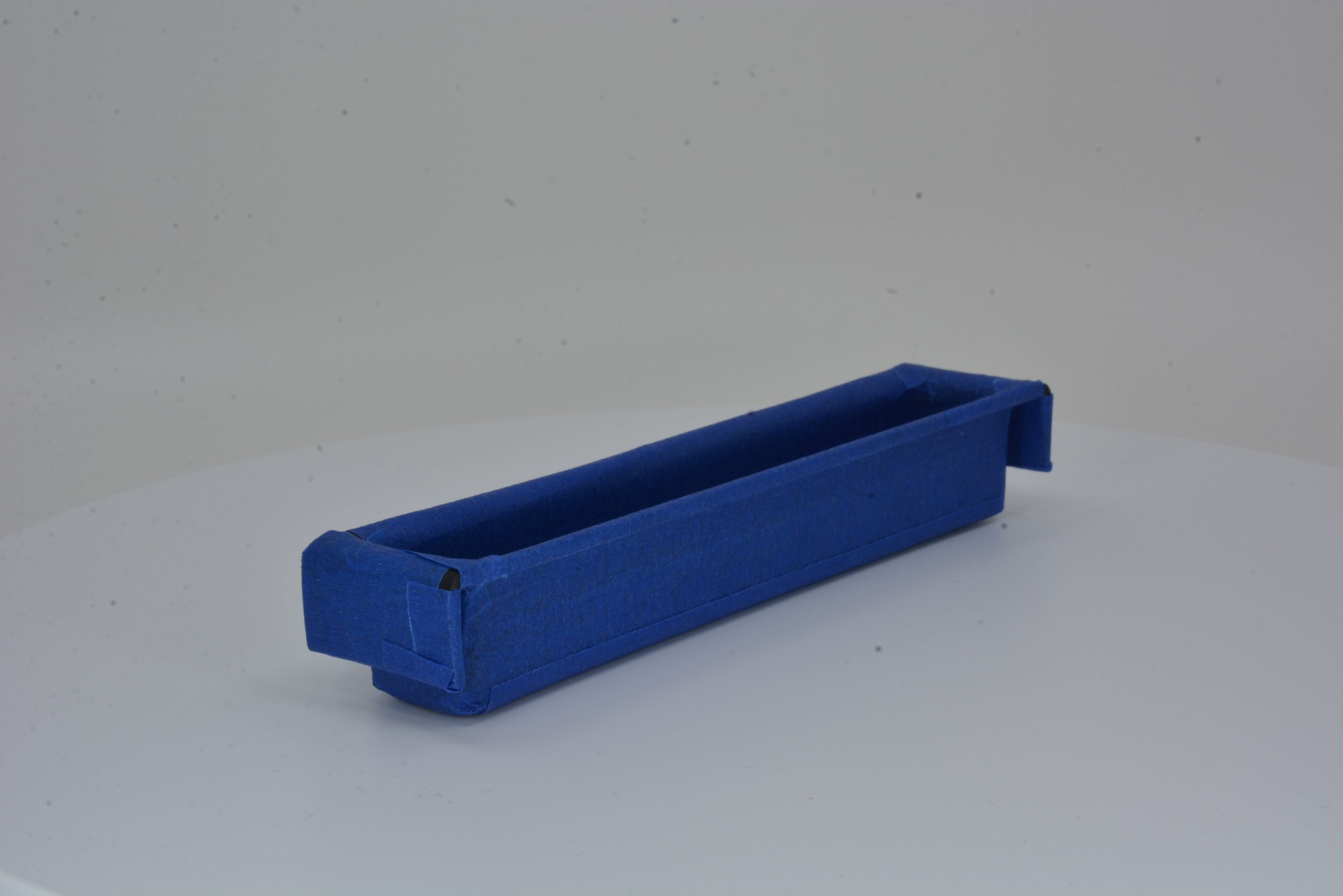
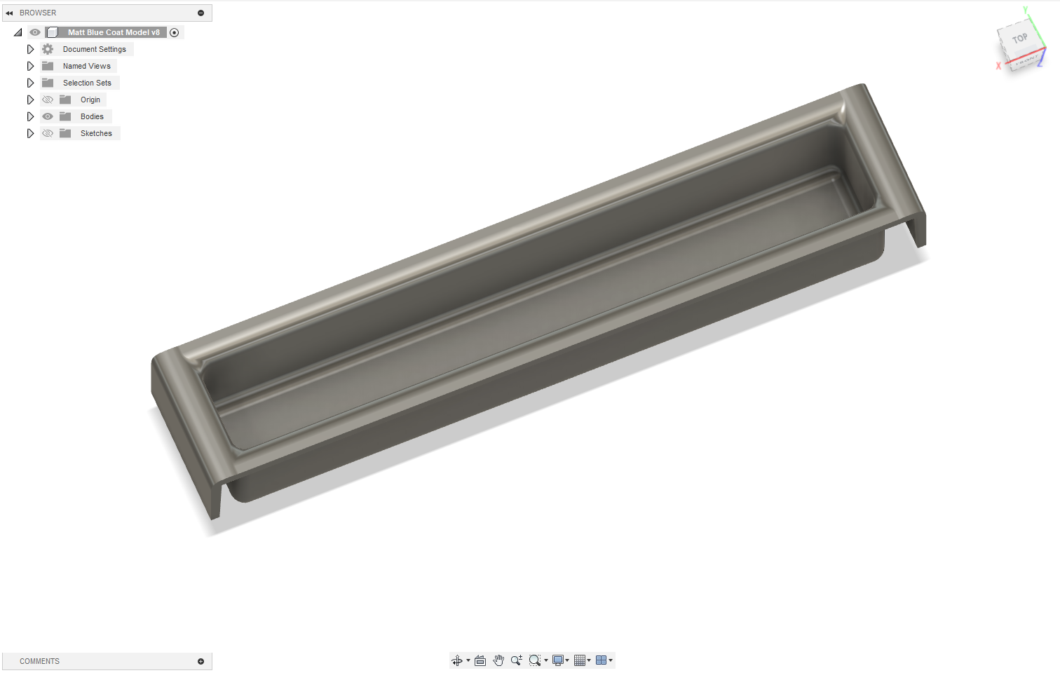
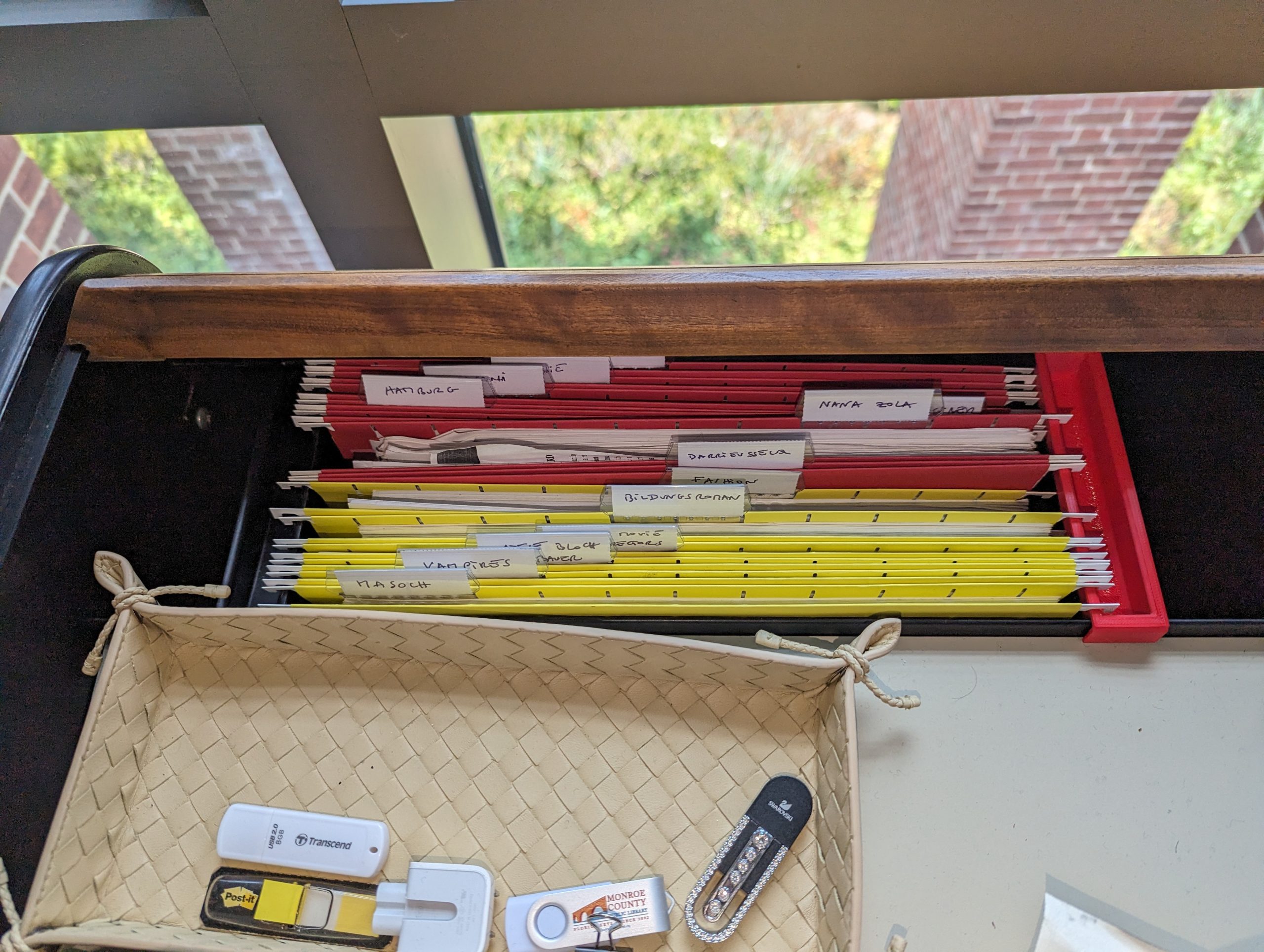
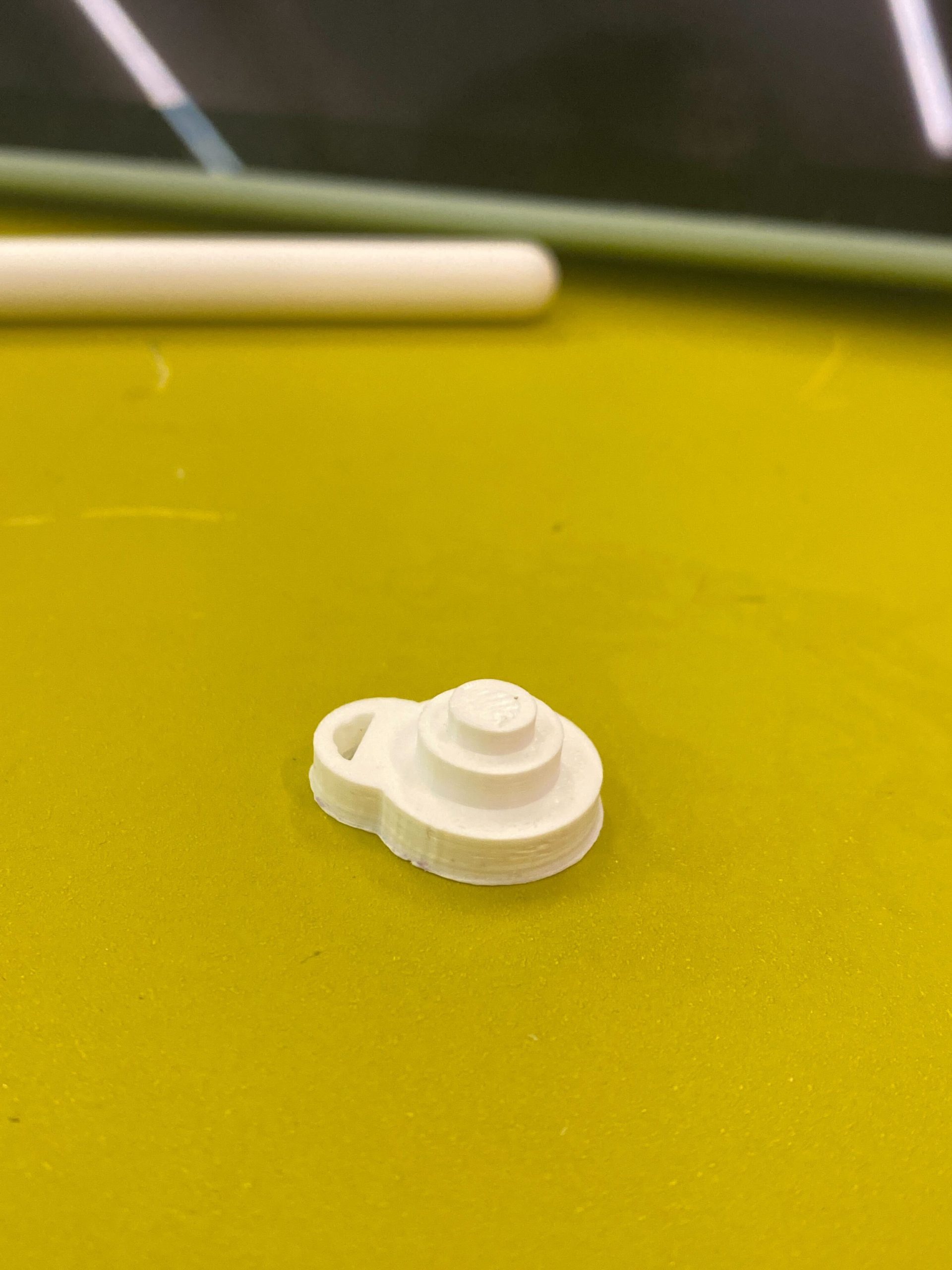
Most recently, Associate Professor of German, Chris Koné, approached the Makerspace with a problem: all but one of the file hanging clips to his beloved office desk had broken. The result: piles of overflowing manila folders surrounding his desk, cramping his office and style. He searched Ebay, Etsy, and Amazon, but was unable to find replacement parts. He even visited a store in NYC that specializes in providing office parts. Alas, the parts were obsolete. So he approached the Makerspace and asked if we might be able to replicate his last remaining viable part.

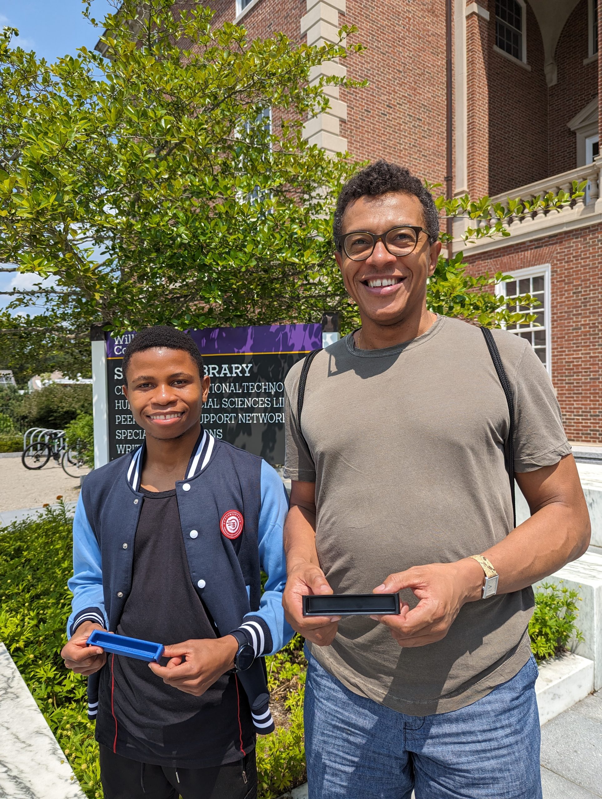
Milton Vento and Chris Koné hold the original and cloned objects.
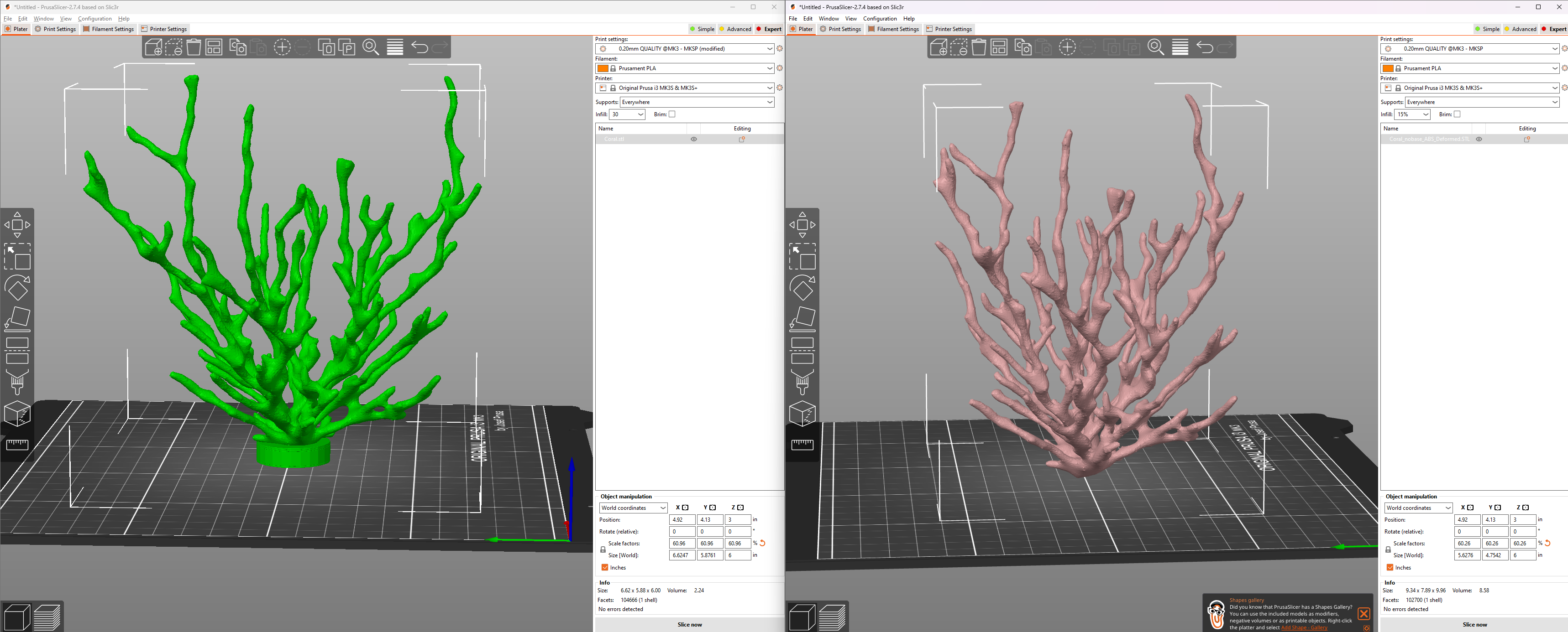
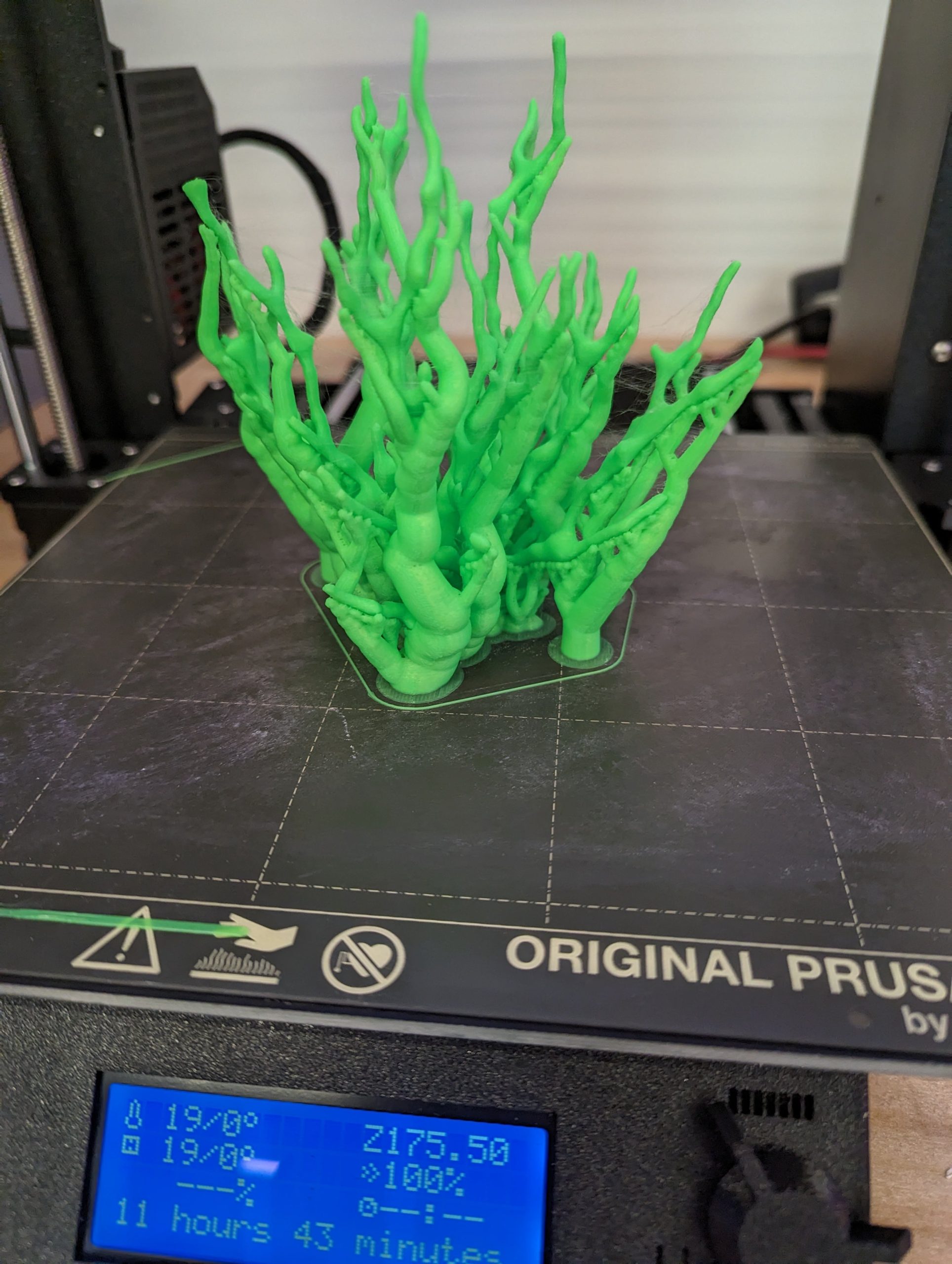
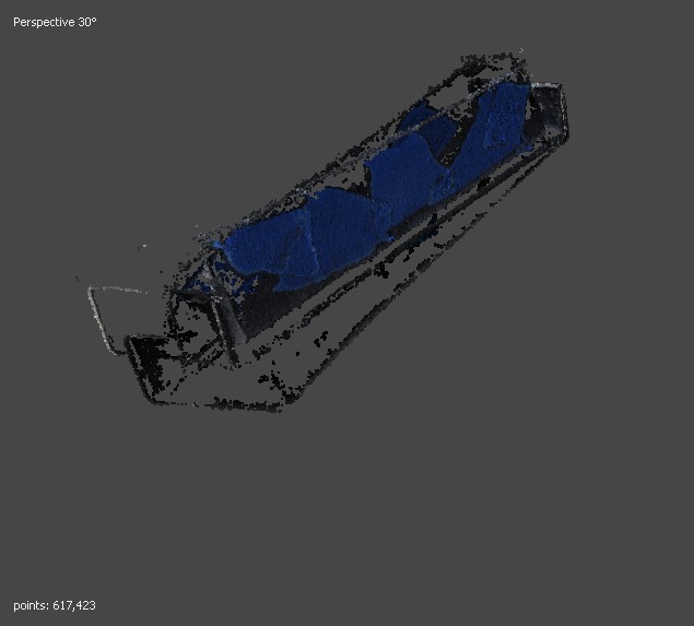
Milton Vento, the Makerspace’s summer student worker, took on the task as his first project, using it as an opportunity to learn photogrammetry, an accessible and low-cost method of taking many photographs of an object from varying angles and then using software to stitch them together into a 3D digital object. He expanded the project by testing four different methods of creating 3D objects using: standard manual DSLR photogrammetry with Metashape software; photogrammetry using a smart turntable that rotates and sends an infrared signal to the DSLR camera, causing it to iteratively release the shutter and then advance the turntable several degrees and then repeat that process; an older DAVID5 object scanner; and the RealityScan app that requires only a smartphone. This exploration resulted in two distinctly more efficient workflows that will become standard use this fall in the Makerspace.
He also successfully re-created a 3D object of the final remaining desk part, and printed and delivered a half dozen of these parts to Chris. Should any of these ever break, the file can easily be retrieved and re-printed.
Contributors: German Department (Professor: Chris Koné), Makerspace (Staff: David Keiser-Clark, Student: Milton Vento)
Future Project Ideas
One upcoming and likely collaboration between the Makerspace and the Zilkha Center would be to laser etch additional sustainably-harvested Hopkins Forest wood slices to create signs for the Williams College Community Garden. Additionally, the Zilkha Center, Makerspace and MCLA Physics and Environmental Center may brainstorm the possibility of creating a larger prototype for upcycling plastic into pellets. The pellets could then be used for injection molding, given to local artists for artwork, or sold regionally; this idea was sparked by Smith College’s collaboration with Precious Plastics.
You can find this blogpost and other sustainability projects at sustainability.williams.edu.