Ever wanted to reuse your old silkscreen without first having to clean off the old paint or emulsion? This innovative process explores reusing a stainless-steel screen by applying new acrylic paint to the screen to create a solid resist, and then, after the paint dries, removing sections of the resist with a laser engraver. This method has the potential to be a more efficient way of creating intricate and customizable screen printing designs, with substantially less prep work.
Inspired by Carleton College’s Makerpedia, this method turns traditional screen printing on its head.

The result of using a laser cutter to burn acrylic paint off of a painted steel mesh screen. Instant “silk screen”. Or is it?
Here’s Why this Rocks
- Reuse it like a pro: Say goodbye to one-and-done screens.
- Freedom to create: Change designs as easily as switching out the acrylic paint resist.
- Laser precision: Get ultra-detailed results with modern tech.
- Perfect for small batches: Quick, easy, and ideal for mini-projects.
How to Make It? (The Fun Part)
I consulted with David Keiser-Clark, Makerspace Program Manager, and Jason Mativi, Senior Science Center Shop Engineer.
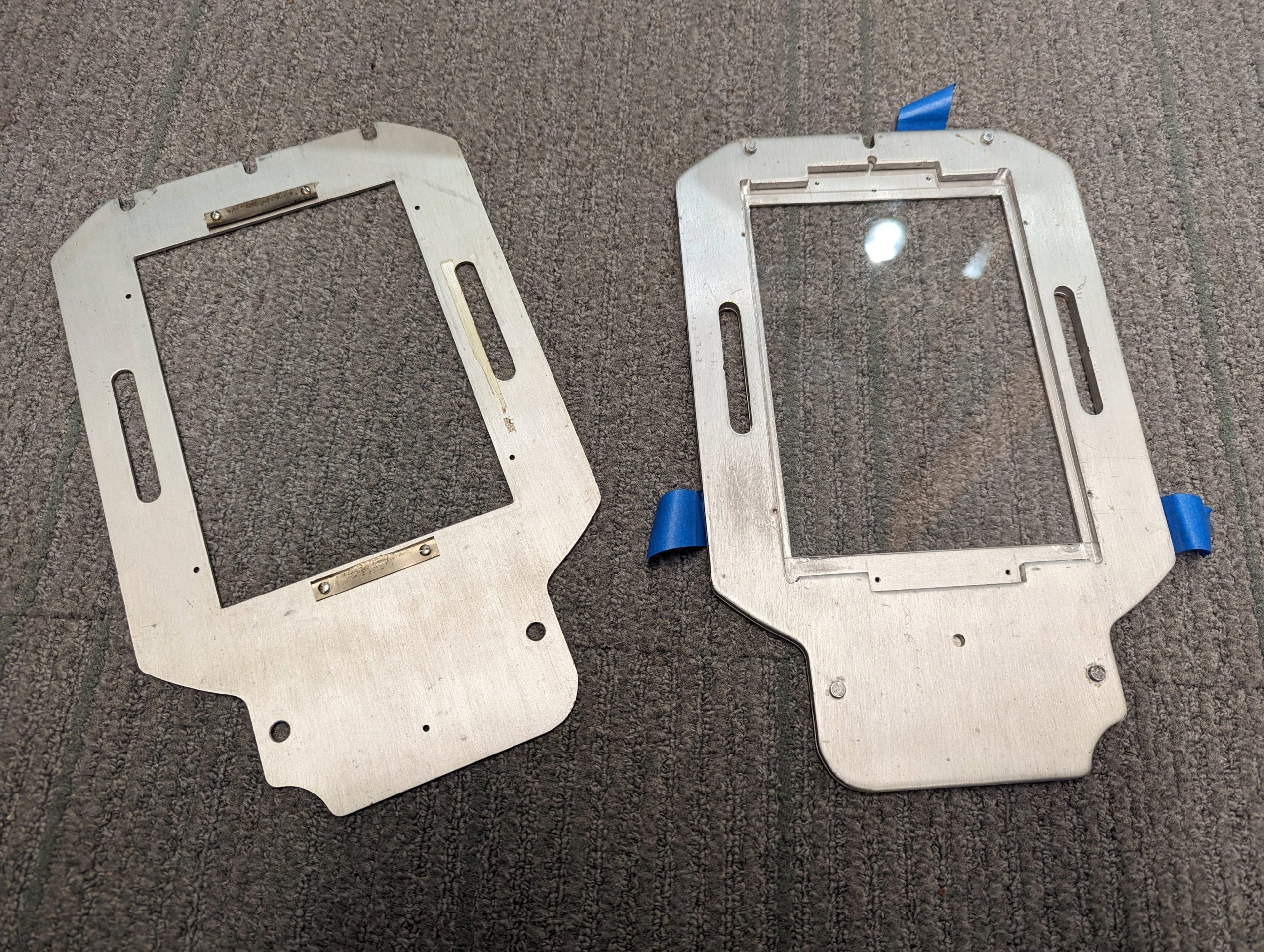
Step 1: Make The Frame
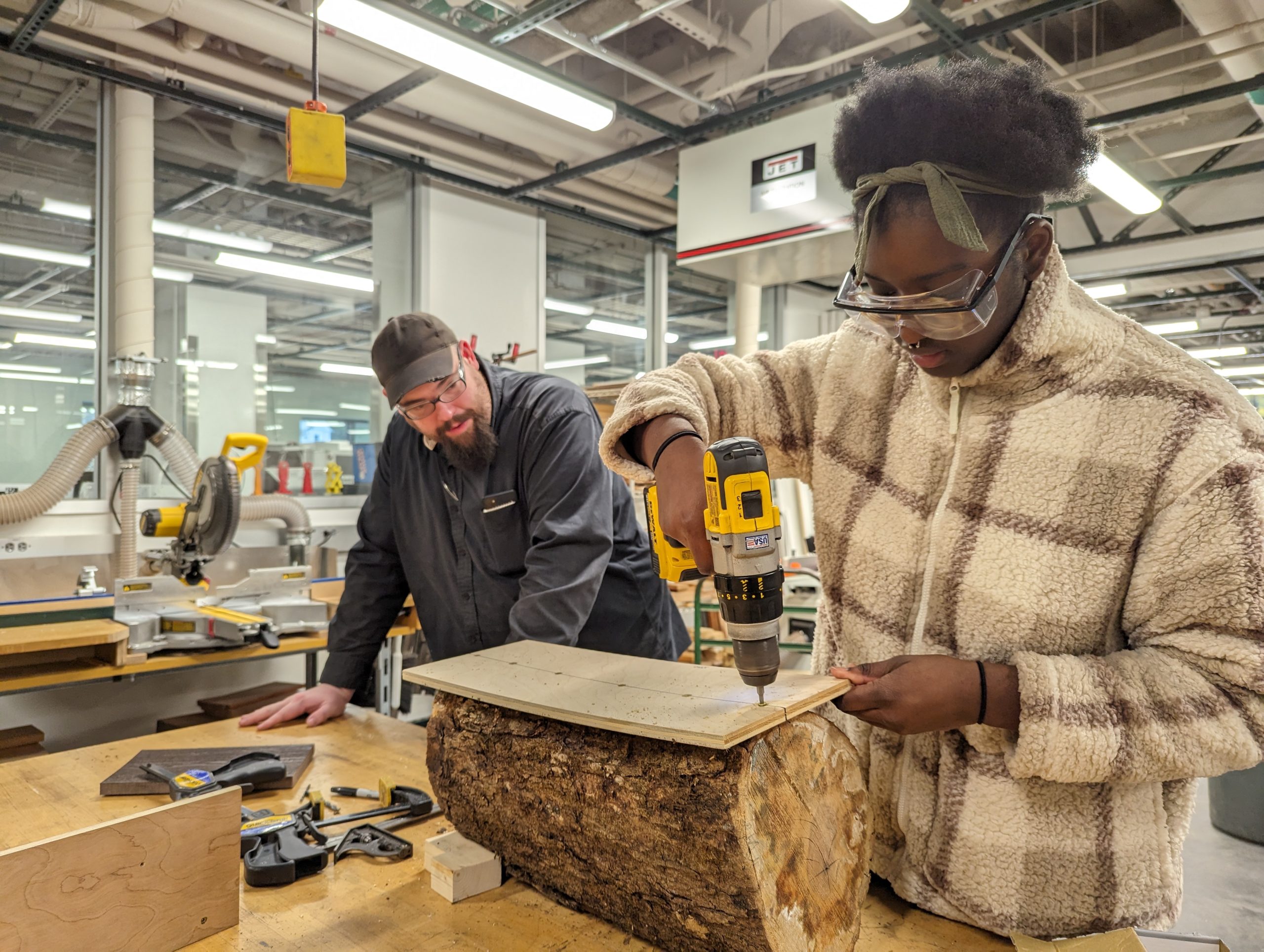
To make the project successful, I had to make a frame for the steel mesh. I learned how to use a metal chop saw in the Science Shop to cut the aluminum extrusions to the desired lengths. Before cutting the aluminum, I made sure to wear safety goggles and to clamp the stock down. I then carefully measured and cut a total of four pieces of aluminum.
I used the corner bracket cube to serve as a connector between the aluminum frame pieces, and screwed each side tight to prevent any wobble.
Step 2: Attach the Screen
I then modified and customized Carleton College’s 3D screen lock. I added more thickness in the base of the screen lock and included holes on each end for the screws to pass through. Each hole has a diameter of 0.27 in.
I cut enough screen mesh to wrap over both ends of the frame. I then had to make two holes on each side of the screen and attached it as tight as possible to the extruded part of the frame. I added the screen lock, pressed, and secured it in place with a screw.
Step 3: Painting the Screen
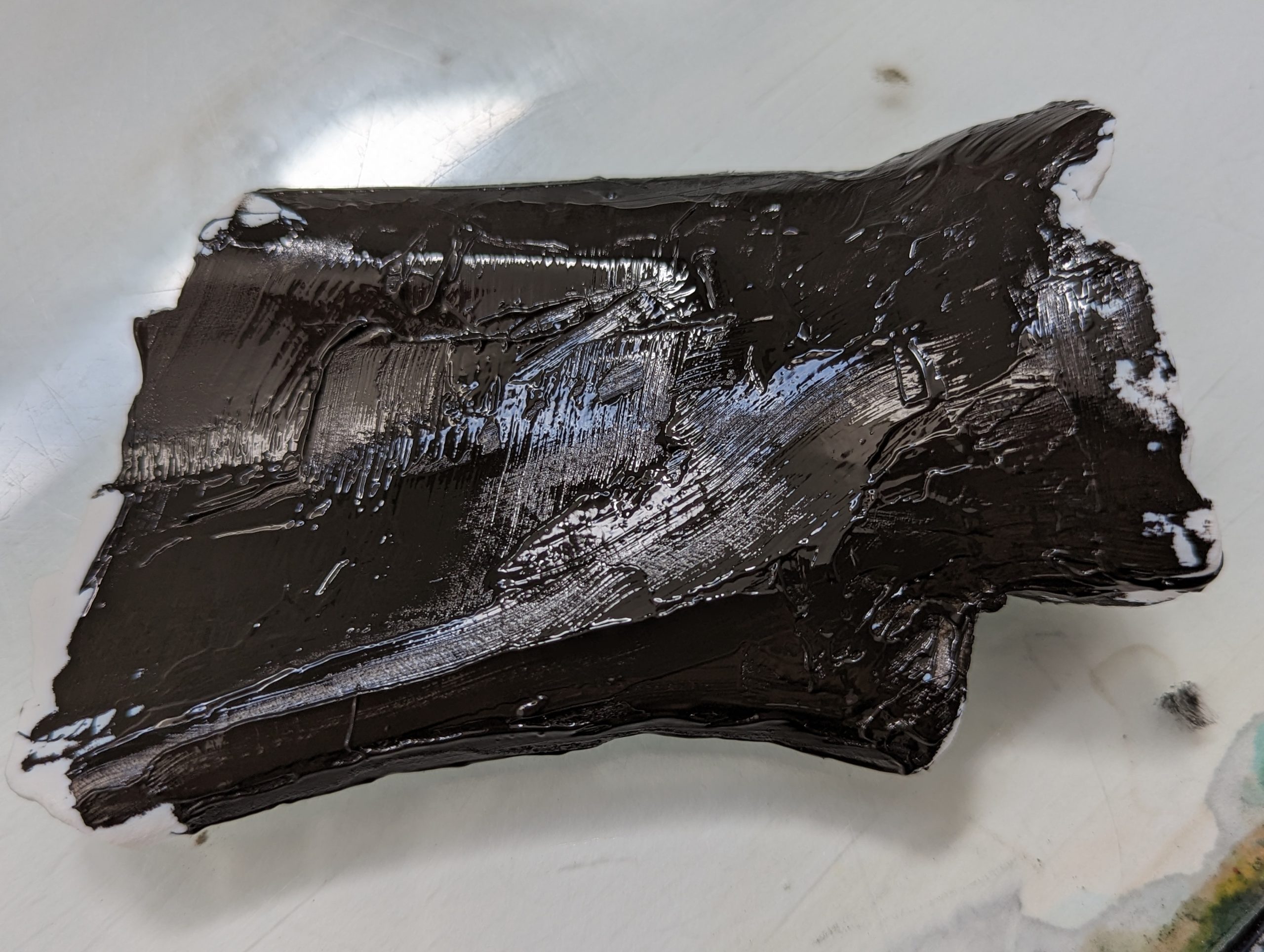
I painted the mesh of the screen with a solid coat of acrylic paint. I found that painting one side of the screen is sufficient.
Step 4: Printing Process

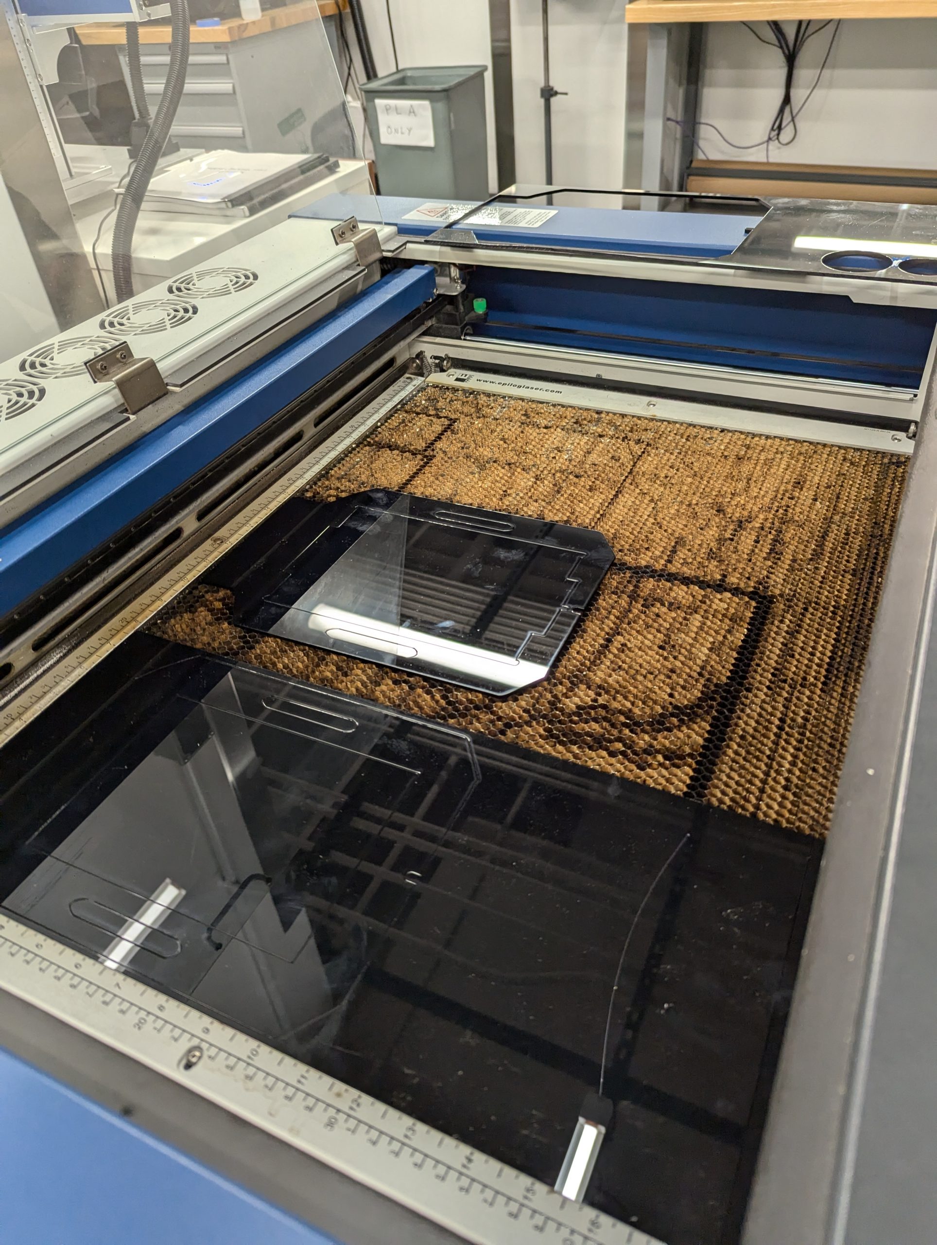
Stephen Sabio ’28 examining the first attempt to use the laser engraver to do a reusable skill stencil.
I placed the screen on top of white drawing paper, with the screen facing the paper. Then, I made sure that it was secured so that it would not move as I applied fresh paint. I used around 10 ml of paint and painted it over the screen nice and slow to make sure that it didn’t bleed. I used the silicone squeegee to apply the paint evenly on the screen. Lastly, I slowly separated the screen from the paper. It was a little sticky, so I had to be careful not to smudge the paint. Sticky? Yes. Smudgy? No.
I may not have successfully created the perfect silkscreen. I think what I learned here is patience. Everyday I learn something new. It is not always about the goal. I was initially so focused about creating the perfect mesh screen, but I think the best part here was the process of figuring out how to make this work the way I wanted it to work. I learned that the beauty of creating something isn’t the result. It is every step you take, every turn of the screw, every laser that passes through, every stroke of the paint. It is those little pieces of an art that makes it a whole.
How Many Times Did I Fail? (A Love Letter to Iteration)
Spoiler alert
It wasn’t perfect the first time.
Or the second.
Or… well, you’ll see.
Unfortunately, we broke the auto-focus plunger (which we don’t use) on the laser engraver, because we set the height for the recessed screen and failed to account for the taller aluminum frame. Collision! (Sorry Mativi!!!) On the positive side, when the new part arrived, we learned how to repair the laser engraver.
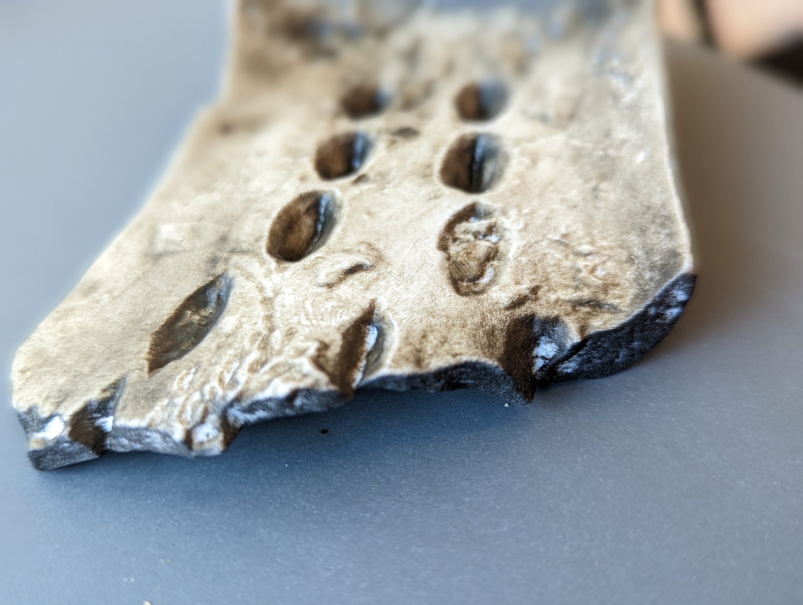
Iteration #1: The first attempt of using the laser engraver to burn a precise design in the mesh screen, I set the power to 26% and the speed to 100%. I repeated this process three times to try and burn through the acrylic paint on the mesh. It didn’t work. The screen was still covered with acrylic paint on the other side of the screen. Epic fail. Paint didn’t budge.
Here’s what I learned: there’s no need to paint both sides of the mesh screen, as that only makes it more difficult to burn the paint off with the laser engraver.

The laser engraver’s first run, etching precision into motion. #Laser engraver in action!

Round two of testing: despite multiple burns, the acrylic paint refused to give in.
Iteration #2: I next set the power to 100% and the speed to 100%. I again repeated this burn three times. It didn’t work. The screen was still covered with acrylic paint on the other side.
Bright side? The laser survived!
Iteration #3: Third time’s a charm, they say. I set power to 100% and the speed to 100%. It was basically the same as the second iteration, but this time instead of passing the laser engraver thrice, I passed it five times. The screen was still covered with acrylic paint on the other side but this time the acrylic was brittle and I was able to remove it using a razor blade and a steel brush. I gently took off all the brittle dried acrylic from the screen. The design survived. It worked! Oops! A new problem: applying fresh paint to the mesh screen results in paint bleeding out around the design borders. The print quality is terrible. There is still something missing. What’s next? I don’t know! Guess we will keep trying.

A test for new solutions: Jason Mativi and Stephen Sabio experimenting with alternative methods after multiple laser engraving challenges.
Iteration #4: A recurring problem that I have identified is that the acrylic paint is challenging to burn away using the laser engraver. It’s time to try an alternative method. Mativi recommended that we try using the water jet to burn away the acrylic paint. So, I went to the Science Shop. And voilà, the water jet cut through both the acrylic paint and the mesh screen. The 30,000 psi water pressure and garnet dust was too strong for the screen material. We initially thought that might occur, but hey, at least we tried!
Iteration #5: Back to the laser engraver. We tried experimenting around the speed and power of the laser engraver. There was no optimal speed and power to completely get rid of the acrylic. However, 100% power and 30% speed almost achieved our desired result. I still had to scrape a little bit of the acrylic off the screen. It was still worth the try!
Finally, it did work on iteration 5! Now, the big question: How many times did I fail? To be honest, I don’t know. I lost track along the way. The important thing is, I, we did it

When the backup fails ( water jet), it is time to go back to the original plan of the laser engraver and try again

After multiple attempts, there was success! Next came printing – an extremely careful process of separating the screen paper with little to no smudges.
Result? Fabulous
But more than just a crisp print, what I really took away from this process was growth. Every failed iteration, every broken tool, every “oops” moment pushed me to adapt, experiment, and stay curious. I didn’t just build a reusable mesh silkscreen—I built patience, problem-solving skills, and a deeper appreciation for the messy magic of making.
The learning process gave me hands-on experience with precision measurement, power tools, and mechanical assembly. I learned how to safely operate cutting equipment, interpret dimensions with accuracy, and ensure structural stability by aligning components tightly. It also sharpened my understanding of engineering tolerances; one loose screw, and the whole frame can wobble!
Beyond just assembly, this part of the process also introduced me to the practical side of design thinking, understanding how each material interacts under tension, and how even minor tweaks to the build can affect the outcome of the print. Turns out, there’s a bit of an art to building things that don’t fall apart under pressure. Literally.
Materials List
- Stainless Steel Mesh
- Aluminum Extrusion
- Silicone Squeegee
- Acrylic Paint
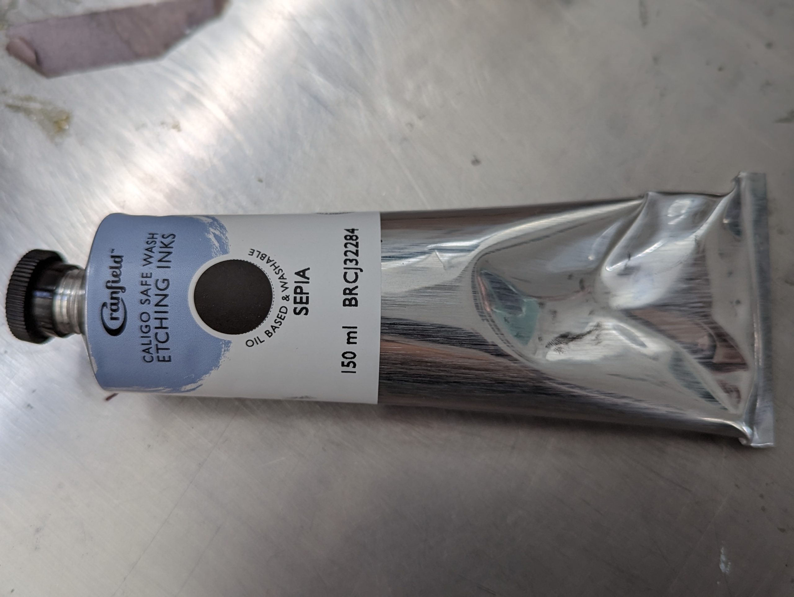
- Screen Printing Ink
- Corner Bracket Cube (20x20x20mm)
- Dimensions; 8.625 in x 8.625 in