 Echoes of the ancient Greek chelys lyre kept appearing in my courses: Greek pottery depicting a lyrist’s playing technique or ancient literature describing its acoustics. These sources inform our knowledge of the lyre, and can in turn be brought to life by attempting to replicate the lyre itself. Endeavoring to experience the music of the ancient world this winter study, I worked with the Williams College Makerspace, Classics department, and many other incredible sources of help to create a playable, sonorous chelys lyre replica.
The First Vegan Lyre… Ever??

My completed ancient Greek lyre sounds amazing!
The ancient Greek chelys lyre, named so for the χέλυς (tortoise) shell used for the soundbox resonator, is said in the Homeric Hymn to Hermes to have first been made by Hermes as an apology gift to Apollo for kidnapping his cows. This was one of the ancient Greek texts I read with my project’s advisor, Visiting Assistant Professor of Classics Marissa Henry, who was an incredible guide throughout the entire project. Reading about the unfortunate tortoise who was first turned into a lyre, I was very glad about my choice to make a fully vegan lyre—no tortoises or cows harmed! In fact, in all my research I did not come across another chelys lyre—ancient or modern—that uses zero animal products. This gave a lot of room for creativity, riffing off of the trial and error of other lyre-makers.
Tortoiseshell Soundbox

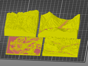
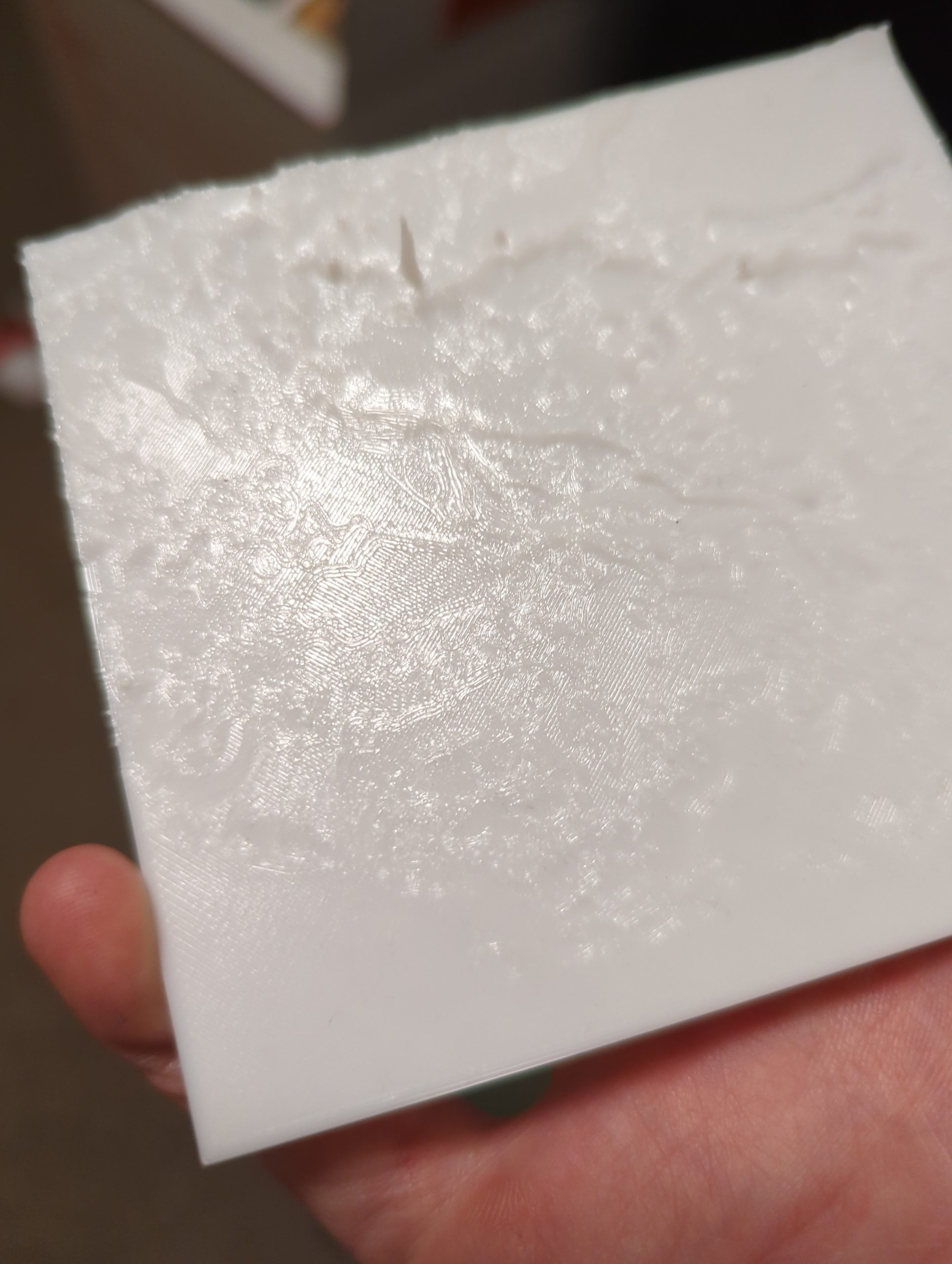
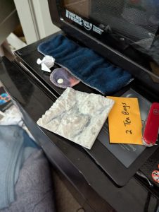
Printing a tortoiseshell replica using the Prusa XL 3D printer to make a fully vegan lyre—no tortoises or cows harmed!
The biggest headscratcher was the tortoiseshell soundbox, which we considered making out of a hollowed-out gourd or a wooden salad bowl. While both are great alternatives, a gourd is quite fragile and unpredictable as a natural object, and a salad bowl felt too easy. Luckily, the Makerspace gives students access to 3D-printers for just this sort of moment. When I asked David Keiser-Clark, the Manager of the Makerspace and FabLab, and a huge contributor to the lyre, if it was possible to 3D print the tortoiseshell, I expected it to be too complicated or not viable—perhaps the material wouldn’t be resonant enough, or a tortoiseshell too complex to print. It turned out to be a fantastic way to replicate the tortoiseshell, using an online 3D scan of a tortoiseshell that I downloaded (as an STL file) and then modified using Fusion 360 and Blender (modeling software) to create strategic holes for the arms of the lyre to enter and the tailpiece to jut out.
Help from an Expert Luthier

Expert luthier Steve Sauvé at Sauvé Guitars in North Adams, Massachusetts.
Next, we had to think about how to build the drumhead of the lyre, usually made by stretching animal skin over the face of the shell. In my research, mylar came up as an alternative, but mylar is not flexible and mouldable in the same way that animal skin is. I learned this and many other luthier insights from Steve Sauvé at Sauvé Guitars in North Adams, Massachusetts. He presented me with an alternative: a mylar banjo head! We decided to fashion it to the lyre by 3D modeling and printing a bespoke insert ring that would snugly support the banjo head, forming the face of the lyre. In the original hymn, the strings of the lyre were made from the guts of Apollo’s cow, and gut strings were primarily used for traditional instruments. For our purposes, nylon proved a great alternative, with ukulele strings being the best fit, which I found with the help of Collar City Guitars in Troy, NY.
And Alumni Woodworkers

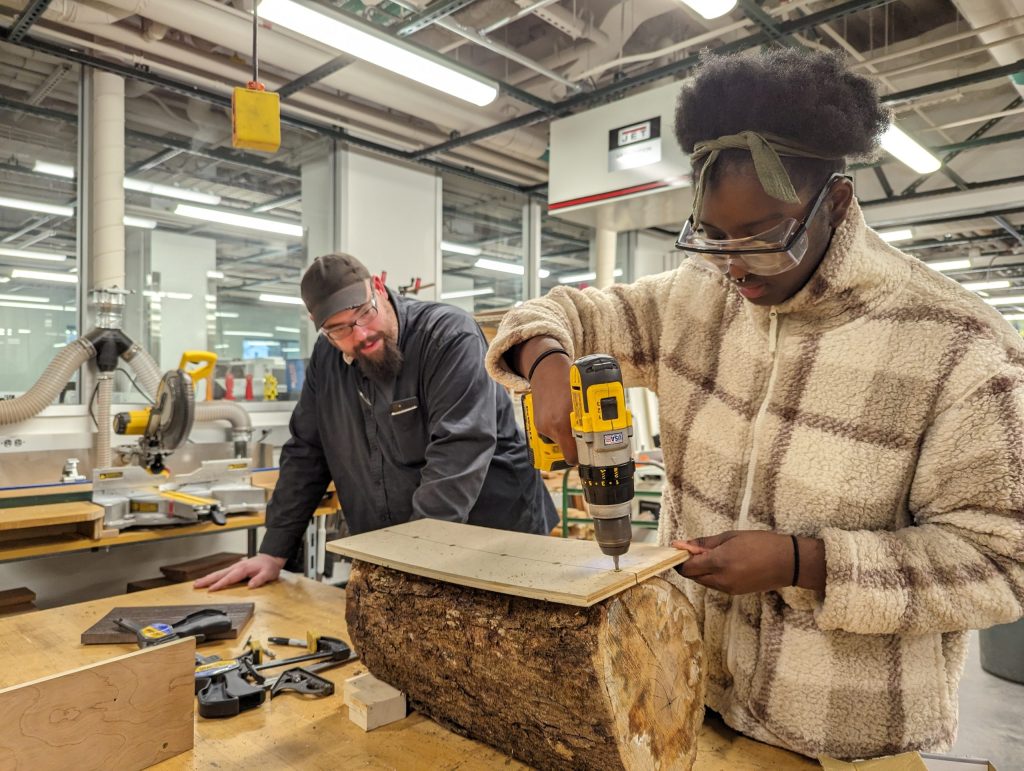
Using a bandsaw to cut one of the lyre’s arms.
Shaping the wood for the lyre was tough to figure out and presented challenges. I had never used power or carving tools, and I was starting from two gorgeous blocks of cherry wood bought from Sauvé Guitars. I learned how to shape and replicate the traditional snaking arms and intricate tuning bulges (these hold the strings and allow them to be adjusted) from the advice of the teachers (all alumni: Seth Rolland, Chris Mullen, and Richard Song) of the winter study course “Introduction to Woodwork: Art, Design and Craft” (WSP 16). They were incredibly helpful, showing me how to safely use a bandsaw to create rough, blocky cuts for the arms and bridge. I called this the “Minecraft version” of the lyre.
Learning to Use a Wood Lathe

Jason Mativi, Senior Science Center Shop Engineer, and David Keiser-Clark were both huge resources who together helped me learn how to safely use the wood lathe and disc sander.
The intimidating wood lathe in the Hopper Science Shop was the key to rounding the rectangular crossbars and tuning bulges (pegs) that maintain the tension of the lyre’s seven strings. Jason Mativi, Senior Science Center Shop Engineer, and David Keiser-Clark were both huge resources who together helped me learn how to safely use these tools. David stayed with (always alert) throughout the entire process, offering me a kind balance of support, guidance, and independence.
The lathe was the tool I had to be the most cautious while operating: it spins the wood very rapidly (~2000 RPM) and I used lathe chisels to slowly transform the rough cut block of cherry into a gorgeous cylindrical object with uniform shape and width. I used the lathe to create two crossbars and 14 wood tuning bulges, then used a stationary disc sander to further shape these pieces and add intentional charring to increase visual contrast. I learned how to use a universal metal bender to shape a stock 3/16” straight metal steel rod into a functional “buckle” that I later mounted in the lyre’s tail (below the bridge) and used to tie off the strings.

A close up of using the wood lathe and lathe chisels to turn the 14 tuning bulges.

14 tuning bulges, turned on the lathe, and some have been sanded on the disc sander, while others await that final treatment.
Spokeshaves and Flowing Organic Curves

Lee Valley spokeshaves set: flat, round, and concave.
David and I returned to the Makerspace, and he introduced me to using high-quality spokeshaves (like two-handed wood planes) to shape the arms: they pull the wood off in super-thin and satisfying ribbons that result in a smoothly curved and organic shape.
However, when I began the dry assembly of these nearly completed pieces, it became apparent that the length of the lyre’s arms were too short to allow for tying off the strings below the 8” banjo head. The lyre required a longer tail. Ack! I brought this problem to David and he suggested using a leftover scrap (from our original cherry planks) to create a contoured half-lap woodworking joint to seamlessly extend the arms. I was running out of time, and he volunteered to do this complicated hand work. He returned it to me the next day and I was able to resume the dry assembly.

Wood joinery: extending the arms by creating a halflap joint, fastened with removable bolts to enable future adjustments.
3D Modeling: The Magic of Creating Custom Shapes and Bespoke Parts
The next challenge was to figure out how to securely connect the 3D printed tortoiseshell with the two cherry arms. A shoutout to Anderson Keiser-Clark, 13, for contributing his Blender expertise that modified the digital tortoiseshell to include snug holes for the arms and tail to pass through. He also created a custom lid that bolts to the base (to allow future maintenance) and included a ring on which to securely mount the banjo head.

3D modeling work with Blender software created exactly matching top and bottom parts that securely hold the arms in place.
Shaping the Bridge and Finally: Assembly!

Sabrina using a coping saw to shape the bridge for the lyre.
I used a coping saw to shape the bridge and create the desired curves. I stained only the 14 tuning bulges, and then used vegan Walrus oil on all of the wood parts to bring out the beautiful highlights of the grain. And finally, I successfully assembled the lyre and tuned the strings. Amazing!
Learning to Play the Lyre

Sabrina Farrell learning to play the lyre with UVM Professor Rachel Fikes.
In order to learn the physical technique of playing the lyre, Dr. Henry and I made our way to Vermont to meet with members of the Call of Kinnaru, a group from the University of Vermont who play new ancient music featuring kitharists among other instrumentalists. Professor John Franklin and Rachel Fikes were kind enough to let me play their lyres and introduce me to the incredible process of developing music from what we know of ancient practices. It was especially enriching to physically hold a lyre, so that I could feel exactly what I was working towards.
Inspiration from the New York City Ballet

The symbol of the New York City Ballet Company is the lyre.
Even outside making the lyre, I got to experience the joy of this instrument in many ways. Artist-in-Residence in Dance Janine Parker, whom I have been learning ballet with since I first came to Williams, took three of us to the New York City Ballet, since the symbol of the New York City Ballet Company is the lyre. Not only that, but it featured a dance called Antique Epigraphs choreographed by Jerome Robbins to music by Claude Debussy, which was an incredible piece inspired by Greek antiquity. This was such an incredible ballet to see and a singularly amazing experience in seeing the ancient embodied.
Teaching Students from the Williamstown Elementary School’s Robotics Team

Members of the Williamstown Elementary School’s Robotics Team.
This independent study also offered me the opportunity to make mini cardboard lyres with 6th grade students from Williamstown Elementary School’s Robotics program, led by Associate Professor of Classics Sarah Olsen. The theme this year for the robotics competition was archaeology! I was so happy to share with them my journey building a lyre and the exercise making cardboard lyres. They are such amazing students and are lucky to work alongside Professor Olsen who first introduced me to ancient Greek language and classics as a whole.
Thank You!
Thank you to everyone already mentioned and all the many others who helped me along the way! This was truly a group effort to build and I’m so thankful for the incredible support in making music.

Starting point was a slab of cherry wood (arms drawn in pencil). Final product is my own custom ancient Greek lyre that is an absolute joy to play!
See Related Articles
The Williams Record: The Artist Otherwise Known As: Sabrina Ferrell ’28 (May 7, 2026, by Edward Maxam)
Classics department hosts evening of ‘new ancient Greek music’ (April 23, 2025, by Rosario Carranza and Tahlia Gerger)