Mayan Tenon: Bringing the Past to Life with 3D Printing

Background

Mayan "Human Head Emerging from Monster Jaws", Late Classic, 600-900 CE, 125 lb., Object number: 1870.1.2

Mayan “Human Head Emerging from Monster Jaws”, Late Classic, 600-900 CE, 125 lb., Object number: 1870.1.2

College campuses hold a wealth of history, blending the stories of their institutions and community with those of the wider world. The epitome of this fascinating history can be found in the Williams College Museum of Art (WCMA). Among the thousands of objects housed here, some carry tales of adventure, cultural exchange, and intrigue that transport us back in time. Between 1870 and 1871, two Williams students took a Lyceum-sponsored trip to Honduras and Belize where they acquired two Maya tenons in the town of Corozal and brought them back to Williams College, where they remain today. These tenons are now studied as part of anthropology and art history courses at the college and have been on view in Object Lab and other exhibitions at WCMA. More information about these artifacts can be found in a student research paper written in 2019. 

Given their fascinating history with the college, the WCMA wanted to send the above pictured tenon, object number 1870.1.2, to the Beatriz Cortez x rafa esparza: Earth and Cosmos exhibition in New York City. The Earth and Cosmos exhibit celebrates cultural and artistic ties to ancient civilizations, making the tenon a fitting addition. However, the tenon is fragile, sculpted from soft limestone, and heavy, about 125 pounds. If it were to be shipped to the show, it would have been a miracle if it arrived in one piece. This logistical nightmare prompted Beth Fischer, WCMA’s Assistant Curator of Digital Learning and Research and Lecturer, to reach out to the Makerspace and request a 3D printed copy at a 1:1 scale model. She even shared the high-resolution photogrammetry 3D scan that she had completed during the pandemic. 

Although shipping a reproduced object eliminates any fear of damage to the original, 3D printing still raises a series of challenges. First, the tenon is significantly larger (23 1/4″ × 8 1/2″ × 18″) than our largest printing bed, meaning we must print it in quadrants and glue them together in the post-processing stage. Second, 3D-printed objects can be fragile, and they may chip or crack if they are jostled during shipping. Third, how do you best transform a 100% plastic object into a material resembling aged limestone?

One quadrant of the 3D printed tenon fills most of the available bed space on the Makerspace's Prusa XL 3D printer; note the "tree supports" are still attached

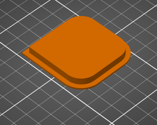
One quadrant of the 3D printed tenon fills most of the available bed space on the Makerspace’s Prusa XL 3D printer; note the “tree supports” are still attached

Printing

We resolved the oversized nature of this object by dividing our model into four roughly equal parts. We printed each quarter separately, and the actual printing times ranged between 10 and 34 hours per each quarter—for a total of about four days of nearly continuous printing.

We briefly experimented with adding mass to the 3D print by pausing the print midway through, then adding steel BBs into the hollow interior infill, and then completing the print. We decided there was little benefit to adding mass, as the object would be on display and would not be handled by the public. We instead focused on durability for shipping purposes. We selected our settings and printed a test piece (representing 1/32 of the entire object) that we then dropped and kicked to subject it to the kind of rough handling it might experience during shipping. We found that a 3mm shell provided a sturdy and durable object. We printed in Sunlu PLA Meta 1.75mm filament (white) with the following specifications: 0.2mm layer height (speed), 15% infill density, triangular fill pattern (low density, strong, fast), and organic tree supports (easy to remove). We configured the Prusa XL to auto-swap filament rolls as each successive 1kg PLA roll ran out. For the largest (34-hour prints), we used 2.3 rolls, and this hot-swapping meant increased efficiency because we did not have to babysit it. 

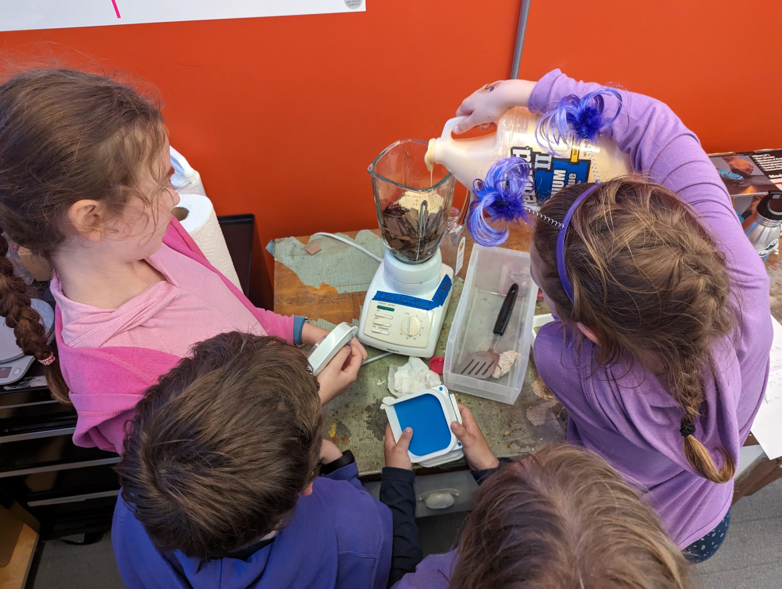
We created the model’s stone-like appearance using a post-processing technique that the Williams Makerspace learned last spring semester from two (then) local 5th graders: Elizabeth Heeringa (she invented the technique) and Anderson Keiser-Clark. Together they applied this technique to a pair of large-format 3D printed Spruces Lions that supported Giuseppina Forte’s ARTS 222 Critical Practice of Architecture: Theories, Methods, and Techniques course. These lions were exhibited in the Williams 2024 Spring Big Arts Show.

Post-Processing Recipe

We used luthier’s woodworking tools (scrapers) to remove extraneous plastic from the flat sides of each quadrant. We then superglued the four quadrants together with CA (cyanoacrylate) glue, and applied three layers of 3M Bondo (a thick epoxy putty used in automobile repair) to hide the seams. We let that dry and then hand-brushed two thin coats of DRYLOK Original Concrete & Masonry Waterproofer; this helped convert the plastic PLA surface texture to the more sandy and gritty nature of the DRYLOCK paint.

We used luthier's woodworking tools (scrapers) to smooth the flat sides of the PLA blocks

We used luthier’s woodworking tools (scrapers) to smooth the flat sides of the PLA blocks

Mayan "Human Head Emerging from Monster Jaws", Late Classic, 600-900 CE, 125 lb., Object number: 1870.1.2

3D printed tenon: 3 of 4 printed quadrants (organic tree supports remain on the lower right block)


3D printed tenon: 4 of 4 printed quadrants (organic tree supports remain on the two blocks on right side)

3D printed tenon: 4 of 4 printed quadrants (organic tree supports remain on the two blocks on right side)

Applying the third layer of 3M Bondo (a thick epoxy putty used in automobile repair) to hide the seams

Applying the third layer of 3M Bondo (a thick epoxy putty used in automobile repair) to hide the seams


Finally, we created an acrylic wash solution by filling two spray bottles (one black, one brown) with a solution of 15% acrylic paint and 85% water. We sprayed on 4 coats, allowing 24 hours to dry between each. It sprays on quite dark, but then dramatically lightens as it drips off. Iterative coats allowed us more control over achieving our final desired outcome.

The 3D printed tenon after being painted with two coats of DRYLOK Original Concrete & Masonry Waterproofer

The 3D printed tenon after being painted with two coats of DRYLOK Original Concrete & Masonry Waterproofer

We were excited to accidentally discover that using a painting hood with strong ventilation (to reduce our exposure to the DRYLOK fumes) changed the spray bottle output and turned it into a very fast-moving and fine mist (think: atomized), and that nearly eliminated drippy streaks. We attempted to use our two colors to recreate the variegated tones of natural limestone by adding extra solution to nooks and crannies, and then we dry-brushed the visual highlights with a stiff, fine brush (using pure acrylic paint) to add some texture. Our goal was never to color match the original Mayan tenon, but rather to create a realistic looking substitute that could be interpreted as being limestone. The painting was completed by Lisa Dorin, Deputy Director of WCMA, and David Keiser-Clark, Makerspace Program Manager.


Lisa Dorin, Deputy Director of the WCMA, spraying the 3D printed tenon with an acrylic wash

The 3D printed tenon after being painted with two coats of DRYLOK Original Concrete & Masonry Waterproofer

Side view of the final 3D printed tenon, after post-processing, weighs about 20 pounds

Side view of the final 3D printed tenon, after post-processing, weighs about 20 pounds

Front view of the final 3D printed tenon, after post-processing, weighs about 20 pounds

Front view of the final 3D printed tenon, after post-processing, weighs about 20 pounds


NYC Exhibition

The final 3D printed tenon was visually stunning, weighed about 20 pounds, and was successfully shipped to Earth and Cosmos, where it is being exhibited from January 29 through May 17, 2025. Beatriz Cortez was very happy with the result and hopes to be able to borrow the print again for future exhibitions. This exhibition-quality 3D print acts as a fascinating interface between artistic expression and cutting-edge technology. Although it was artificially fabricated, it still carries the history and cultural significance of the original piece in a manner that can be transported from location to location and shared with the broader community. This work is a part of Williams College’s story, but also a part of many other stories, and I’m thankful to have had the opportunity to share it. 

3D printed tenon being wrapped for shipment to exhibition in New York City

3D printed tenon being wrapped for shipment to exhibition in New York City

3D printed tenon on display at Earth and Cosmos exhibition, New York City

3D printed tenon on display at Earth and Cosmos exhibition, New York City


Acknowledgments

This project was made possible thanks to the collaborative efforts of Beth Fischer and Lisa Dorin (WCMA) and Makerspace student workers Harris Longfield ’27 (me) and Elena Sore ’27, with support from David Keiser-Clark.

Publications Mentioning this Work


Life After Williams: Stitching Memories Workshop

Contents of upcycled mending kit includes a block printed "Strive for Zero Waste" by Leni Fried of the Old Stone Mill Center.

Contents of upcycled mending kit includes a block printed “Strive for Zero Waste” by Leni Fried of the Old Stone Mill Center.

As a Resident Director, one of my responsibilities is to plan and execute a Life After Williams (LAW) event. LAW events are designed to teach students practical skills that will be useful after we leave Williams, skills that we might not learn in the classroom. For my LAW event, I decided to partner with the FabLab to hold a mending and hemming workshop. Participants were invited to learn basic sewing skills and take home a mending kit, promoting both self-sufficiency and sustainability.

To plan this event, I reached out to David Keiser-Clark, Makerspace Program Manager, who was truly invaluable throughout the process. He connected with the Old Stone Mill Center, a zero-waste makerspace in nearby Adams, MA, and sourced mending kits for our workshop including upcycled materials such as antique sewing scissors, button thread, regular thread, denim scraps for patches, embroidery thread, cork, pins, safety pins, sewing needles, a few buttons, chalk, and a thimble. The Old Stone Mill assembled these materials into custom zippered pouches that they created from upholstery samples.

Students participating in the Life After Williams workshop created by the Residential Life Team

Students participating in the Life After Williams workshop created by the Residential Life Team

50 upcycled mending kits for this and future mending workshops, created by the Old Stone Mill Center in Adams, MA

50 upcycled mending kits for this and future mending workshops, created by the Old Stone Mill Center in Adams, MA

Students participating in the Life After Williams workshop created by the Residential Life Team

Students participating in the Life After Williams workshop created by the Residential Life Team

Final elements, such as fabric tape measures, in-house 3D printed sheaths (for the scissors), seam rippers, and industrial thread, were added to each kit the day before the event. Each kit was a unique work of art and clearly made with care. The event was held on the final day of Earth Month, and I’m grateful to the Zilkha Center for helping to publicize it.

Reflecting on the event itself, I would say it was a great success. I am grateful to Maile Ruiz ‘26, a FabLab student worker, for sharing her expertise as an instructor. Nine students attended, and two of them learned to sew for the first time. I personally mended one of my favorite scrunchies and helped a fellow senior fix the cuff of her sweater. As we all sat around the table, our conversation revolved around the emotional and environmental value of caring for clothing. The senior reflected that she had brought the sweater with her to study abroad and therefore it held memories for her. In repairing it, not only was she able to decrease clothing waste, she was also able to retain the physical reminder of her memories. It was gratifying to know that these kits might empower students to take more agency in maintaining their clothes and, by extension, in reducing waste.

(Thank you to Anderson Keiser-Clark for contributing his Fusion360 design for the scissors sheath. We 3D printed these in flexible TPU (50% infill) and they offer a perfect grip.)

PrusaXL 3D printing a batch of scissors guards

PrusaXL 3D printing a batch of scissors guards

Fusion360 design for the scissors sheath.

Fusion360 design for the scissors sheath.


Alumni Reflection: My Experience in the Makerspace (Mohammad Faizaan ’23)

Mohammad Faizaan '23

Mohammad Faizaan ’23

During the tour of campus at First Days my freshman year, I heard that Sawyer Library had a room full of 3D printers, a VR headset, video gaming rooms, and production studios. It sounded awesome! But in the whirlwind of starting college, learning how to college, and figuring out where the good study spots were, I forgot about it.

That changed about a month into the semester during my Chemistry 151 class. We had a virtual lab in the library and were handed these tiny 3D-printed water molecules. I was fascinated. They weren’t just models—this represented water! Something we drink every single day and is vital to sustaining life. Someone had taken the time to turn their PyMOL rendering of water tangible. That moment is what led me back to the Makerspace. 

Walking into the room for the first time felt like stepping into a playground for creativity and experimentation. I was hooked. I loved tech, had always been the kind of kid to open up old phones to see what was inside (sometimes even managing to put them back together—other times… not so much. Sorry Dad!). Even though I was leaning toward medicine, not engineering or computer science, the Makerspace gave me an outlet to nurture that side of me—the part that loved to build, break, problem-solve, and tinker.

During that first visit, I met Matthew Roychowdhury ’21, who would later become my student mentor. He mentioned that they were hiring, and I happened to be looking for a campus job. After meeting with the Director of OIT, Jonathan Leamon, he handed me a key. Neither of us knew that this key would unlock a really formative part of my Williams experience. 

From day one, the Makerspace was a place where curiosity came first. You didn’t need to know how additive manufacturing works or a background in engineering; all you needed was a willingness to try, to ask questions, and to experiment. As such, I started small: printing fun models, learning the quirks of different printers, experimenting with different filament types. Eventually, I was assembling machines, running workshops, and helping classmates bring ideas to life—and occasionally causing disasters. 

I’ll never forget the infamous Blob of Death. We, at the makerspace, had been struggling with build-plate adhesion for a while my first year. After trying to mess around with different options—turning up the build plate temperature, attaching masking tape, or using a glue stick—I decided to solve it my own way: slow down the print by 80%, crank up the build plate temperature, and let it run overnight. Little did I know. I came back the next morning to find out that my model had not adhered. The filament kept coming, thus forming a giant blob that melted into the extruder head and damaged it. I felt terrible. But it was also a turning point. I learned how to fix the extruder, how to not fix adhesion (pro tip: use glue sticks!), and most importantly, how to take responsibility for mistakes and learn from them. 

Later, I became a student manager, which meant mentoring others, troubleshooting constant printer issues, and helping lead through unpredictable challenges like COVID-era policies when the library would cut power at 11 p.m., destroying all overnight prints. We got creative, supported each other, and laughed through the chaos. It was teamwork, community, and a kind of joyful resilience (which we needed when all printers were down). 

What stood out to me, however, was how interdisciplinary the Makerspace was. It wasn’t just about technology. It was a space for expression, creativity, learning, and most importantly experimentation. I used the VR room to walk around a chemical model of a protein and explore ß-sheets and α-helices. I became an architect for a day when I helped design a room in blender (and gave structural, get it?, advice on why we wouldn’t be able to print a model with a floating roof). I saw studio art majors, computer scientists, and biology students all using the same machines for completely different goals. That kind of intellectual cross-pollination is rare, and it’s something that I now realize prepared me well for the kind of collaboration and creative thinking needed to solve problems. 

Now, as a medical student, I’m not building 3D models every day, but I am working to solve problems, think critically across disciplines, and striving to be creative in doing so.  Medicine, like the Makerspace, is about adaptability, collaboration, and understanding how different systems work together. The hands-on experiences I had building, fixing, experimenting, and supporting others in the Makerspace genuinely helped shape the kind of thinker—and person—I am today. 

In fact, one of the most unexpected things the Makerspace gave me was a sense of advocacy even during my first days in undergrad. When I first joined, our machines were outdated and constantly breaking. As fun as it was to come up with creative solutions, we needed more reliable tools. So, Roychowdhury ’21 and I came up with a case for a new printer, presented it, and learned how to effectively present it to Leamon. Not only did Leamon help us purchase two new printers, but this experience helped me grow closer to him—to the point wherein he wrote one of my letters of recommendation for medical school! That experience helped shape the confidence I relied on for my undergraduate advocacy and current day advocacy in religiously informed healthcare, Muslim representation in medicine, and health equity, more broadly. 

The Makerspace gave me a space to be curious, to grow into a leader, and to build confidence in skills I didn’t even know I had. It helped shape not just how I work, but how I think, and who I want to be. I’m endlessly grateful for the community I found there, and I hope future students continue to find the same joy, creativity, and purpose—whether their path lies in tech, art, science, medicine, or something else entirely.

Mohammad Faizaan
Rush Medical College ’28
Williams College ’23
BA in Chemistry and Religion


Astral Sea: Weaving Memory, Migration, and Movement at Williams College

This year, Williams College collaborates with the Clark Art Institute to become a vital site for the next chapter of Astral Sea, an ongoing series by multidisciplinary artist Tsedaye Makonnen. Known for blending performance, sculpture, and textile arts, Makonnen’s work explores the intertwined themes of resilience, memory, and migration. Her residency at Williams extends this exploration through a series of collaborative workshops, performances, and community engagements that invite both participation and reflection.

Kusika dancers shroud themselves in fabric for Makonnen’s performance. (Photo courtesy of Brad Wakoff.)

Kusika dancers shroud themselves in fabric for Makonnen’s performance. (Photo courtesy of Brad Wakoff.)

The Vision Behind Astral Sea

Tsedaye Makonnen unpacking and seeing the woven mylar demo for the first time.

Tsedaye Makonnen unpacking and seeing the woven mylar demo for the first time.

At its core, Astral Sea is about creating immersive, multi-sensory experiences that transcend traditional performance boundaries. The project weaves together live dance, sculptural installations, soundscapes, and reflective textiles, many of which are inspired by Makonnen’s light sculptures. These elements come together to embody themes of diasporic memory, spiritual resilience, and the cosmic connections between people and places.

In this iteration, produced by Williams College and presented at the Clark, Makonnen collaborates closely with Kusika, the college’s African dance and percussion ensemble, and a broader network of faculty, students, and staff across departments like WCMA, Theater, Dance, Makerspace, FabLab, Science Shop, and the Sculpture Studio. This partnership is supported by the Gaudino Fund and fosters a unique interdisciplinary environment where art, technology, and community engagement converge.

Materials as Storytellers

Staff and faculty examining Zea Barker's fabric for Tsedaye Makonnen’s Astral Sea series. From left to right: Kyle Yager, Samantha Pasapane, Tsedaye Makonnen, and Sandra Burton.

Staff and faculty examining Zea Barker’s fabric for Tsedaye Makonnen’s Astral Sea series. From left to right: Kyle Yager, Samantha Pasapane, Tsedaye Makonnen, and Sandra Burton.

A central feature of Astral Sea is its sculptural textiles—large, flowing fabrics adorned with shimmering materials that move and reflect light during performances. These are not just aesthetic choices; they are vessels for storytelling. Makonnen and her collaborators have been experimenting with a range of unconventional materials:

Blue fabrics and appliqué

Custom-made textiles in various sizes, embellished with symbols, mylar cut-outs, mirrored acrylic, and smelted aluminum disks. These components create a dynamic visual and acoustic experience as performers interact with the fabrics.

Upcycled aluminum: Samantha Pasapane of the Sculpture Studio worked with the team’s requests to forge and cast aluminum—from the Science Shop’s CNC shavings —into blocks. Samantha smelted the aluminum, cast it as a rectangular block, cut a slice with a metal bandsaw, and then polished that to a mirror reflective finish. This was one of many material experiments that the team conducted to determine what kinds of materials would function most effectively being sewn into the fabrics. There were even discussions of sourcing aluminum from cans collected at the U.S.-Mexico border, linking the material to Makonnen’s broader themes of displacement, asylum, and echoing global migration. Like a variety of materials tested, this particular process was not selected for adorning the final textiles.

Aluminum shavings from the Science Shop's CNC machines were repurposed and cast into aluminum blocks.

Aluminum shavings from the Science Shop’s CNC machines were repurposed and cast into aluminum blocks.

Samantha Pasapane of the Sculpture Studio experiments with forging aluminum from CNC shavings into blocks, and then polishing to a mirror reflective finish. Left: cutting a slice with the bandsaw; Middle: polishing with a drill mounted 3M abrasive pad; Right: the final slice is highly polished.

Samantha Pasapane of the Sculpture Studio experiments with forging aluminum from CNC shavings into blocks, and then polishing to a mirror reflective finish. Left: cutting a slice with the bandsaw; Middle: polishing with a drill mounted 3M abrasive pad; Right: the final slice is highly polished.

Mirrored acrylic and mylar

Laser-cut into symbolic shapes, these reflective elements catch light during performances, amplifying the visual impact and connecting to Makonnen’s signature light sculpture motifs.

Jason Mativi of the Science Shop uses the Epilog Laser Helix machine to cut mylar for decorating fabric.

Jason Mativi of the Science Shop uses the Epilog Laser Helix machine to cut mylar for decorating fabric.

Mirrored acrylic was also laser cut in the Science Shop on an Epilog Laser Helix machine.

Mirrored acrylic was also laser cut in the Science Shop on an Epilog Laser Helix machine.

Bells and sound elements

Some fabrics incorporate bells and metal disks, adding an auditory layer that enhances the sensory immersion of the piece.

Every material choice is intentional, contributing to a tapestry of textures, sounds, and reflections that mirror the complexity of human migration and spiritual continuity. The fabrication process itself is a collaborative effort, involving professionals like Zea Barker (Textile Fabricator) and numerous student volunteers, ensuring both technical precision and educational engagement.

The Process: Collaboration in Motion

The residency at Williams has been punctuated by a series of workshops designed to engage students and community members in the making of Astral Sea. These include:

Textile and Soft Sculpture Workshops

Participants learned about the materials and techniques used to create the sculptural fabrics, from cutting mylar symbols to sewing reflective appliqués.

Weaving reflective mylar into Tsedaye Makonnen's Astral Seas project. Left: Before weaving the mylar, the loom must be threaded to create a warp. Middle: Creating a demo weaving in the FabLab to demonstrate a variety of mylar widths and explore looser or tighter weaving of materials. Right: Final woven demo. Weaver: David Keiser-Clark.

Weaving reflective mylar into Tsedaye Makonnen’s Astral Seas project. Left: Before weaving the mylar, the loom must be threaded to create a warp. Middle: Creating a demo weaving in the FabLab to demonstrate a variety of mylar widths and explore looser or tighter weaving of materials. Right: Final woven demo. Weaver: David Keiser-Clark.

Movement Workshops

Led by Makonnen and Kusika director Sandra Burton, these sessions explored how performers embody and interact with the textiles, integrating dance, ritual, and improvisation.

Oral History Workshops

Led by Makonnen and WCMA Curator Roz Crews, these sessions explored storytelling as a critical component of the performance.

Technology Integration

The Makerspace, FabLab, Science Shop, Sculpture Studio, and Zea Barker explored innovative elements like muscle wires (shape-memory alloys), body-mounted fans to billow fabric, an air curtain, and even virtual reality body tracking tools to map movement and choreography. In addition, these teams tested a variety of materials that could connect with the billowy fabric including: varying weights and types of handle attachments; hand-woven mylar that could serve as a trim; 3D printed rainsticks to add sound. These experiments reflect a commitment to pushing the boundaries of performance through interdisciplinary exploration.

Iterating with a variety of fans to explore billowing effects for the dancer's fabric. From left to right: Kyle Yager, Tsedaye Makonnen, and Jason Mativi. Out of frame: David Keiser-Clark.

Iterating with a variety of fans to explore billowing effects for the dancer’s fabric. From left to right: Kyle Yager, Tsedaye Makonnen, and Jason Mativi. Out of frame: David Keiser-Clark.

Using powerful fans to create billowing effects. From left to right: Kyle Yager and Jason Mativi. Out of frame: Tsedaye Makonnen and David Keiser-Clark.

Using powerful fans to create billowing effects. From left to right: Kyle Yager and Jason Mativi. Out of frame: Tsedaye Makonnen and David Keiser-Clark.


Looking Ahead: Performance and Community

The culminating performances for this phase of Astral Sea are set for Fall 2025, including a major presentation at the Clark Art Institute. These events will activate the sculptural textiles through dance, light, and sound, transforming spaces into living canvases of migration, memory, and cosmic connection.

Through these efforts, Astral Sea is not just an artwork—it is a living, breathing collaboration between artist, institution, and community. It offers a platform for reflection on shared histories and futures, reminding audiences of the unseen threads that connect us across time, space, and culture.

A student rehearsal of Tsedaye Makonnen’s Astral Sea series.

A student rehearsal of Tsedaye Makonnen’s Astral Sea series.

More Information

Darkroom Meets MakerSpace: How 3D Printing Transformed a Photography Class

What happens when a darkroom tool goes extinct, but twenty students still need it? The class had everything: a large-format camera, a darkroom, and eager students. It lacked only one thing: a negative holder that no longer existed. A negative holder is a device that keeps a piece of photo flat and steady during printing or scanning, and it is crucial because it ensures the image stays sharp, properly aligned, and free from distortion or damage.

The solution? Make One.

The original, nearly impossible to find, negative holders

The original, nearly impossible to find, negative holders

Last Winter Study, Daniel Goudrouffe, the Photo Technician for the Spencer Art Building, taught a winter study class called “Creative Portrait in the Darkroom,”  where students experimented with black-and-white film and created photomontages. The class utilizes a large-format view camera that produces 4×5-inch negatives, perfect for cutting, collaging, and combining with digital negatives to create layered portraits. However, there was one obstacle: the darkroom’s negative holders, which were essential for fitting these large negatives into the enlarger, were impossible to find online. The school’s enlarger was a rare, older, and slightly larger 5×7-inch model.

How We Solved the Problem

Using the Epilog to laser cut the negative holders.

Using the Epilog to laser cut the negative holders.

Daniel collaborated with Harris Longfield ‘27, a fellow makerspace worker, and Jason Mativi, Senior Science Center Shop Engineer, to design new holders from scratch. First, using Fusion 360, Harris and I carefully traced the original holder’s dimensions, while Mativi laser-cut and 3D-printed prototypes. After testing the first model and correcting a few asymmetries, the final versions worked flawlessly. The extra holders made a huge difference: instead of waiting in line for a single holder, ten students could now pair up and share five holders.

With the new equipment, students took their projects to the next level, pushing them further than ever. Instead of cutting paper prints, a traditional photomontage method, they cut and layered actual negatives, both film and digitally produced, to craft a one-of-a-kind composition. The larger 5×7 enlarger provided extra space around the 4×5 negatives, allowing them to add new visual elements and more information. This combination of old-school technique and modern tools opened a world of possibilities for image-making.

The five laser cut negative holders

The five laser cut negative holders

Perhaps the most striking result was how effortlessly the 3D-printed holders fit into the darkroom workflow, showing no loss of quality compared to the originals. By blending engineering with art, the project not only solved a practical challenge but also expanded the creative possibilities of analog photography, which shows how new technology can enhance and support classic film practices.

Surprises!

What surprised me most about this project was how naturally problem-solving morphed into a creative discovery. Initially, I viewed the missing negative holder as a straightforward hardware issue that required a technical solution, but I ultimately learned more: how to sketch and model a design, how to test and refine it, and the importance of teamwork in an environment where ideas are constantly evolving.

More importantly, I realized technology and art aren’t two separate worlds–they can actually amplify each other. By designing the new 3D-printed negative holders, we didn’t just replace a piece of equipment; we opened up new possibilities for creative image-making and expanded the possibilities of what a darkroom class could be. For me, that was a powerful reminder that creativity doesn’t exist in isolation: it grows when collaboration, technical skill, and art intersect. I’ll carry that forward into future projects, whether it’s prototyping or approaching any problem with both imagination and practical thinking.

Next Steps

Looking ahead, I can imagine this project leading to a shared toolkit for photographers everywhere. With tools like 3D printers and open-source design platforms, we can expand the idea by posting our files and guides online, making it possible for other darkrooms to thrive despite having vintage tools. I’d love to see this small innovation grow into a network that preserves classic practices and continually improves them through modern engineering. 


Wood, Memory, and Heritage: The Making of Engraved Gifts for Repatriation

Before: red maple wood discs, sliced from a fallen tree in Hopkins Forest

Before: red maple wood discs, sliced from a fallen tree in Hopkins Forest

Last spring, I worked on a project in the Makerspace that involved creating engraved wood slices as gifts for a reburial ceremony. This event was the reburial of the ancestors of the Stockbridge-Munsee Community. The Makerspace collaborated with Bonney Hartley, the Historic Preservation Manager at the Stockbridge-Munsee Historic Preservation office, to work on these slices. They were intended as a token of appreciation to the museums that assisted during the repatriation process. The reburial held deep significance; it was not only about returning the ancestors to the earth, but also about restoring wholeness and dignity to a community that had long been separated from its history.

The event aimed to reunite the ancestors’ remains with the funerary objects originally intended to accompany them. Over time, many of these items had been separated, often displayed in museums as artworks or stored away in boxes and plastic bags. The process of carefully unpacking, organizing, and preparing the materials for reburial required significant effort. Under the Native American Graves Protection and Repatriation Act (NAGPRA), the team undertook considerable legal and logistical work to ensure the ancestors and their belongings could be returned. Before the repatriation, they were in 10 different museums or federal collections agencies across various collections.  After years of collaboration, the team successfully reunited and reburied them, working in partnership with organizations such as the National Park Service and the U.S. Fish and Wildlife Service.

Connection to Place and Heritage

This process was deeply grounding for Bonney and the community, reaffirming their connection to place and heritage. This process restored and further grounded a sense of identity and place in the world. To them, it was truly meaningful to rebury ancestors, reunite them with the objects they were intended to be buried with, and return them to the earth.  It was, to some extent, a way to repair the past, the harm of being separated from their final resting place. It was a profound act of healing and restoration.

The wood slices were not only to appreciate the museum, but also all the people who supported them during this process. It was also an opportunity to express gratitude to the numerous staff members and individuals who work at these museums and federal institutions that hold the collection, and to appreciate those who dedicate significant time and energy to collaborating with them. Even though the focus was on the ancestors, there were people in the scenes who made it happen through goodwill and hard work. To Bonney, this gift is akin to a traditional practice and a form of reciprocity, acknowledging the mutual relationship that exists between them.

Bonney said, “It was hugely meaningful to have a piece of our homelands…” emphasizing how sharing these wood slices extended the Tribe’s tradition of gift-giving and reciprocity. Through the wood slice, in collaboration with the Makerspace and Williams College, they helped offer this gift at the reburial ceremony, and to give one piece of our homeland here in this other location for the reburial. It helps to continue the tradition of gift-giving during such an emotional and spiritual moment, restoring some aspect of the Tribe’s history.

The process of creating these gifts involved a lot of reflected care and intention:

Sanding

We began by carefully making the surfaces even to prepare the wood for engraving.

Sanding: We began by carefully making the surfaces even to prepare the wood for engraving.

Sanding: We began by carefully making the surfaces even to prepare the wood for engraving.

Laser Engraving

The Tribal Seal was then laser-engraved into each slice, and all the details were captured.

Using the Epilog Laser Engravier

Using the Epilog Laser Engravier

Finishing with Natural Oil

A few coats of natural oil protected the wood in order to enhance its texture and grain.

Applying non-toxic Walrus wood oil finish

Applying non-toxic Walrus wood oil finish

Adding Hardware

Finally, hardware was attached so each slice could be hung on a wall.

Back: hardware was attached so each slice could be hung on a wall

Back: hardware was attached so each slice could be hung on a wall

Project completed!

Project completed!

Reflection

For me, making the wood slices was more than a creative task; it was an act of participation in collective healing. It reminded me that craftsmanship can carry history and serve as a bridge between institutions and Indigenous communities.. Through this experience, I gained a deeper understanding of the history of the Stockridge-Munsee Community and the cultural significance behind the reburial event. It was truly moving to witness the respect, collaboration, and care that went into every step of the repatriation process. It’s also remarkable how the Makerspace’s efforts can be part of such a significant event, bringing together creativity, heritage, and community in a powerful way. 

LIFT Program at the Makerspace

Casen working with the Prusa XL 3D printer

Casen working with the Prusa XL 3D printer

The Learning Interventions for Teens (LIFT) program is a mentorship-based program held at Williams every winter study. This program pairs Williams College students with teenagers involved with the Berkshire County juvenile justice system. It offers teenagers an opportunity for personal growth, skill-building, and creative exploration. Over the course of three weeks, students engage in hands-on projects centered around art, photography, 3D printing, and other disciplines.

During our 2025 winter study, the Makerspace partnered with one of the mentor-mentee pairs, Sarah Sousa ’28 and Casen, respectively. Casen was interested in 3D printing and was eager to learn more about how he could use it for his project. Casen was interested in printing two cars that he envisioned using a black filament. David Keiser-Clark, the Makerspace Program Manager, and I gave Sarah and Casen a tour of the Makerspace and shared an overview of all the resources and tools that were available to them. I then worked with Casen and showed him the entire procedure involved in 3D printing, starting from slicing the 3D models to loading the filament and eventually initiating the print. After our demonstration, Casen was ready to implement the entire 3D printing process by himself.

One of Casen's 3D printed model cars

One of Casen’s 3D printed model cars

Altogether, the printing process for both cars took two days to complete. Once the prints were finished, the task of removing the supports—structures that help to stabilize the print during the process—was still a challenge. Removing the supports is usually straightforward, but it was a tricky process for these cars, yet Casen carefully removed them without damaging the prints. He was very patient with it and developed his own innovative techniques to remove them. 

During this time, Casen and Sarah also worked together on their final presentation—which I had the chance to attend on the last day of Winter Study. It was exciting to see all of the interesting projects that students in the program had been working on. The projects covered a range of topics, including nail art, attorney mentorship, and music. It was also lovely to see mentors and mentees receive their certificates of completion. I felt genuinely inspired to see how Williams’ resources helped Casen and other students explore and build upon their interests.

Soft Robots, Hard Ideas: Injection Molding Potential at a Liberal Arts College

An example of a silicone injection molding product, showcasing the material's flexibility.

An example of a silicone injection molding product, showcasing the material’s flexibility.

You might think that silicone injection molding sounds like something reserved for manufacturing plants. Yet, here at the Williams College Makerspace, we can find ways to bring this exciting technology to life using everyday construction tools and 3D printing. This isn’t just engineering—it’s a creative exploration, turning seemingly ordinary objects like caulking guns into tools for building soft robots. At its core, a silicone injection molding project attempts to push the boundaries of what can be done in a liberal arts setting. It sees engineering as a form of art, a craft, and a discipline that invites exploration. As we work towards a silicone injection molding setup, we’re also building a community of thinkers and creators who can look at a caulking gun and see a tool for designing robots. With support, we’ll be able to take projects like these further, offering more students the chance to bridge art and science in new and unexpected ways.

By bringing injection molding to the Makerspace, we’re making a bold statement: at a liberal arts college, the sky’s the limit. Whether you’re a computer science major, a robotics enthusiast, or just someone curious about hands-on creation, this is a project where technology meets artistry and creativity knows no bounds.

Why Construction Tools in a Liberal Arts College?

At first glance, using caulking guns, mixing nozzles, and blowout adapters might seem unusual at a college better known for Shakespeare than silicone molds.

Jack Scissor Stand platform used under the mold to align it perfectly with the nozzle; prevents leaks or uneven filling.

Jack Scissor Stand platform used under the mold to align it perfectly with the nozzle; prevents leaks or uneven filling.

Yet, in our Makerspace, we’ve discovered ways to effectively combine conventional tools (i.e., wrenches, bolts), digital tools (e.g., 3D modeling and printing software), and small machines (3D scanners and printers) to explore hands-on solutions to academic problems. We are able to use these accessible tools to achieve effective results without needing expensive, industrial-scale equipment. These tools can be potent gateways into multidisciplinary learning. By blending traditional tools with advanced (or emerging) digital technologies, we encourage students from diverse academic backgrounds—ranging from studio art, history, and philosophy, to computer science—to collaborate, share perspectives, and approach problem-solving creatively. More than just crafting parts, we’re cultivating a vibrant, interdisciplinary community at Williams.

A caulking gun. This is the primary tool used to push the silicone through the cartridges and into the mold. It provides the necessary pressure for injection.

A caulking gun. This is the primary tool used to push the silicone through the cartridges and into the mold. It provides the necessary pressure for injection.

2-part Silicone Cartridges. These hold the silicone material (typically a 1:1 ratio of two parts that mix and cure into a flexible silicone).

2-part Silicone Cartridges. These hold the silicone material (typically a 1:1 ratio of two parts that mix and cure into a flexible silicone).

Static Mixing Nozzles. These ensure that the two parts of the silicone mix properly before being injected into the mold.

Static Mixing Nozzles. These ensure that the two parts of the silicone mix properly before being injected into the mold.

A blowout adapter. This tool helps clean the cartridges so that they can be reused, reducing waste and ensuring a cleaner process.

A blowout adapter. This tool helps clean the cartridges so that they can be reused, reducing waste and ensuring a cleaner process.


Robots with a Gentle Touch

A soft robot arm picks up a piece of celery. Credit: Soft Robotics, a Cambridge-based robotics company.

A soft robot arm picks up a piece of celery. Credit: Soft Robotics, a Cambridge-based robotics company.

Imagine crafting robots capable of gently handling fragile objects—robots that sense touch, pressure, and temperature, just like living organisms. Silicone injection molding is a fantastic way to create complex, flexible parts with incredible precision. Using a 2-part silicone system and a caulking gun, we’re designing a setup where liquid silicone is injected into a mold and cured, resulting in strong and flexible parts. By experimenting with this technology, we learn the practicalities of fabrication and expand what’s possible in soft robotics research on campus. Each part we make brings us closer to designing robots that can perform tasks with a gentle touch and responsiveness that other kinds of (rigid) robotics can’t achieve. At the core, the process is surprisingly simple yet fascinating. Imagine squeezing liquid silicone into an optimally crafted mold, where it settles and cures, creating detail with precision. It’s like utilizing a high-tech caulking gun, but with a twist—turning liquid into a finely molded solid form.

Our silicone injection molding project opens up some interesting real-world applications. For example, soft robotics has applications in healthcare by aiding minimally invasive surgical procedures and using silicone-molded tools to handle tissues carefully.

These aren’t just fascinating theoretical ideas; they’re practical innovations being explored at Williams, especially within our Computer Science Department under Professor Jim Bern. Specifically, it is intended for use in classes like CSCI 345 – Robotics and Digital Fabrication, aligning closely with Professor Bern’s research interests in soft robotics.

Harvard researchers equipped soft robotic grippers with embedded sensors that can sense diverse inputs such as movement, pressure, touch, and temperature. Credit: Ryan L. Truby/Harvard University

Harvard researchers equipped soft robotic grippers with embedded sensors that can sense diverse inputs such as movement, pressure, touch, and temperature. Credit: Ryan L. Truby/Harvard University

Researchers at Cornell University have developed a soft robotic hand with a touch delicate enough to sort tomatoes and find the ripest one. Credit: Huichan Zhao/Organic Robotics Lab, Cornell University

Researchers at Cornell University have developed a soft robotic hand with a touch delicate enough to sort tomatoes and find the ripest one. Credit: Huichan Zhao/Organic Robotics Lab, Cornell University


Optimization: Making The Most of Things

One of the biggest lessons was in optimization when conducting equipment research. When you’re given a budget and a task, you need to be efficient with your use of money and essentially get the most bang for your buck. In concrete terms, if you find two sets of static mixing nozzles—one that costs $45 and another that delivers the same results that goes for $15—you’d optimally pick the latter. Researching various construction tools to create a concept model of our DIY silicone injection molding device reinforced to me how impactful thorough pre-production research and budgeting can be. 

An example of a DIY Silicone Injection Molding device.

An example of a DIY Silicone Injection Molding device.

Reflection

Working on technological projects has transformed my educational journey. The Makerspace isn’t just a workshop. Here, I’ve learned that exploration, trial and error, and collaboration are as crucial as technical proficiency. By engaging with staff, faculty, and peers, my understanding of the larger world of technological innovation has deepened significantly, showing me just how powerful hands-on learning at a liberal arts institution can be.

Special thanks to Divya Sijwali (’28) and David Keiser-Clark, Makerspace Program Manager, for supporting this blog post!


Printing History: Bringing The Beaver Mill Back to Life

Inspiration to Creation

Photo of the Beaver Mill geographical area from the Big Art Show. The material used is eucalyptus matt board, an environmentally friendly product as compared to traditional acrylic or MDF, and it was laser cut in the Science Shop on an Epilog Laser Helix machine.

Photo of the Beaver Mill geographical area from the Big Art Show. The material used is eucalyptus matt board, an environmentally friendly product as compared to traditional acrylic or MDF, and it was laser cut in the Science Shop on an Epilog Laser Helix machine.

The first time the digital blueprint of the Beaver Mill appeared on my computer screen, I could hardly imagine it becoming real. This historic site, standing quietly in North Adams, was about to transform from a mere collection of pixels into a tangible piece of art. As part of Grace Espinosa’s ’26 ARTS 222 – Critical Practice of Architecture course, our mission was bold yet simple: craft a detailed 3D printed model for the Williams College Big Art Show. Beyond being an academic project, our process and production turned out to be a dynamic intersection of art, technology, architecture, and history.

Grace, the stakeholder and driving artistic force behind this project, shared her vision clearly: “We were inspired to create a 3D printed model of the Beaver Mill to introduce in the architecture section of the Big Art Show.” She wanted viewers to vividly experience the historical site students had been exploring all semester, bringing their classroom discussions to life in a practical, memorable way.

ARTS 222, taught by Assistant Professor of Architecture and Environmental Studies Giuseppina Forte, challenges students to transform architectural spaces through innovative design interventions. Throughout the semester, students develop skills in architectural drawing, graphic design, and digital and physical 3D modeling. They also engage deeply with design strategies such as spatial hijacking and détournement, learning to rethink conventional ideas of space and time. This Beaver Mill project has become a practical demonstration of these powerful ideas.

Navigating Challenges with Creativity

This is a 3D rendering of a split-section of the Beaver Mill that we printed so as to be able to test the internal structural integrity.

This is a 3D rendering of a split-section of the Beaver Mill that we printed so as to be able to test the internal structural integrity.

Our biggest challenge? The size limitations of the Makerspace’s 3D printers. The solution was as simple as it was elegant: we used the Prusa Slicer to split the model into three parts. While this meant a careful, precise assembly with glue afterward, it allowed us to maximize scale and achieve a stunning 24-inch model. Grace noted, with satisfaction, that splitting the model “didn’t impact the final presentation much,” making this strategic decision effective in the end.

Collaboration: Art Meets Technology

This is one of three printed parts of the Beaver Mill. We printed it with "organic tree supports" that are designed to support overhanging structures (like the roof overhangs). We later removed these supports and the result was a cleanly printed section of the building.

This is one of three printed parts of the Beaver Mill. We printed it with “organic tree supports” that are designed to support overhanging structures (like the roof overhangs). We later removed these supports and the result was a cleanly printed section of the building.

Grace had never attempted 3D printing before, making the Makerspace’s role in the project essential. She described this collaboration as transformative: “Working with the Makerspace made the project possible… your facilities and technical knowledge brought the model to a much higher level.”

David Keiser-Clark, Makerspace Program Manager, explains how the Beaver Mill project perfectly embodies the Makerspace’s mission of providing practical, hands-on experience with digital fabrication. “This project directly supported the architectural course goals by giving students real-world experience in modeling and computer-aided design software,” David stated.

David firmly believes in interdisciplinary learning, emphasizing that projects like the Beaver Mill offer students invaluable skills. “Interdisciplinary collaboration encourages critical thinking and practical problem-solving skills students carry forward into their careers and lives beyond Williams,” he explained. This project perfectly encapsulated the blending of creative artistry and technical proficiency.

The Spirit of the Beaver Mill

Grace envisioned visitors observing and actively engaging with the model, appreciating the Beaver Mill’s distinctive texture and structure. The carefully chosen scale and attention to detail turned the model into an interactive experience, inspiring curiosity and exploration about the site’s potential as an artistic hub.

This is the left-most section of the Beaver Mill building with most of the external tree supports removed.

This is the left-most section of the Beaver Mill building with most of the external tree supports removed.

This is the final 3D printed object with all three sections glued together, using cyanoacrylate (CA) glue!

This is the final 3D printed object with all three sections glued together, using cyanoacrylate (CA) glue!


The Magic Moment

This is the finished Beaver Mill model, as it appeared in the Big Art Show. This model shows the post-processing acrylic painting that Grace Espinosa '26 applied!

This is the finished Beaver Mill model, as it appeared in the Big Art Show. This model shows the post-processing acrylic painting that Grace Espinosa ’26 applied!

For Grace, the project’s highlight was unmistakable: “Seeing the model printed for the first time was incredibly rewarding.” After countless hours of refining the digital design, watching the Beaver Mill physically materialize felt almost magical. This moment embodies the Makerspace spirit: turning ambitious ideas into real, tangible outcomes through creativity, technology, and collaboration.

Projects like the Beaver Mill not only captivate participants and viewers but also shape the Makerspace’s future. David highlighted that “each new project fosters deeper connections and opens doors to innovative ideas across the campus.” Events like the Big Art Show and reflecting on these stories inspire future ambitious projects, encouraging faculty and students alike to imagine what’s possible.

Reflecting on the Beaver Mill project, it’s clear that the Makerspace is more than a lab—it’s a space where creativity and technology meet, where collaboration flourishes, and where students like Grace (and myself!) can transform dreams into realities!

Who knows what we’ll create next?


How We Added Webcams to our 3D Printers

The Importance of Remote Monitoring

A screenshot showcasing the Prusa Connect web portal for a Prusa XL printer.

A screenshot showcasing the Prusa Connect web portal for a Prusa XL printer.

This past academic year, I enabled remote monitoring for our Prusa XL and Prusa MK3S printers. I did this because it makes life a bit easier for us student workers. 3D printers are a fickle technology, and failed prints are common due to an object failing to adhere to the print bed, the filament becoming tangled, or a variety of other common issues. Because of this, many Makerspace workers have resorted to stopping by the Makerspace multiple times during long prints, making sure everything is going according to plan. For this reason, Prusa has designed a piece of software called PrusaLink that can connect both their older and newer printers to the Prusa Connect web portal. Upon learning of this, I began to work towards connecting our printers to the Internet so we could check on the status of prints in real-time and even cancel failing prints, all from our phones.

Bringing the Printers Online

A close-up view of the Raspberry Pi Zero 2W Single-Board Computer with a 3D-Printed Bracket attached to it and 4 pins soldered to the board.

A close-up view of the Raspberry Pi Zero 2W Single-Board Computer with a 3D-Printed Bracket attached to it and 4 pins soldered to the board.

For our Prusa XL, this task was easy. The Prusa XL, being a newer printer, has native support for Wi-Fi and simply requires connecting it to the Williams College network. However, some modifications were necessary for our older Prusa MK3S printers. For each of those, I connected a Raspberry Pi Zero 2W single-board computer. This small board, the one pictured above, is an entire computer that can connect to the back of our 3D printers using four pins I soldered to it. These pins transfer power from the 3D printer to the tiny computer, as well as data about the printer which is then sent over the Internet. This is achieved through a software called PrusaLink, a custom Linux-based operating system developed by Prusa that runs on the board.

I soldered these pins, installed the operating system onto a micro-sd card, and mounted a 3D printed bracket designed to prevent electrical shorts with double-sided tape.  I then plugged the boards into the back of the 3D printer and powered them back on. Once powered on, we connected to the IP address listed on the printer’s screen, configured them for remote monitoring, and were able to start monitoring! We could now view the current status of the printers, control them, and upload files to them remotely! However, there was still one problem – we could not yet visually monitor the prints.

Installing Cameras

A 3D-printed camera mount attached to a Prusa MK3S.

A 3D-printed camera mount attached to a Prusa MK3S.

For all of our printers, we ended up designing custom mounts for the camera module we purchased, the Arducam OV5647. This module was chosen because of its cheap price, good-enough visual quality, and direct connection to the Raspberry Pi’s camera connector via a ribbon cable. Our main design principles were that we wanted a mount that followed the nozzle so the current layer was always in the center of the camera, while still showing the print below. I attached this mount to the X motor carriage on the Prusa MK3S, as this allows the camera to stay focused on the printhead. The hexagon pattern matches Prusa’s design language with their printers while preserving airflow, as the fan on the printhead can move very close to the camera mount. I have released this design to the public, and you can find both the STL and Fusion 360 files on the Printables website

A case designed to hold a raspberry pi zero and a camera module monitors a print on the Prusa XL.

A case designed to hold a raspberry pi zero and a camera module monitors a print on the Prusa XL.

For the Prusa XL, a different design was used. The XL has all the functionality of PrusaLink built in, but without a way to directly connect a camera. Therefore, we used the same single-board computer, a Raspberry Pi Zero 2W, running the 64-bit release of Raspberry Pi OS Lite. This gives us a very lightweight operating system that is accessible through the command line for running software. On this computer we set up this code by a github user, which uses the API provided by Prusa to send snapshots from the camera every 10 seconds to the Prusa Connect web portal. I found this mount for a standard webcam on the Printables website, and built my design based on this, adding a box where the webcam would normally mount onto it that holds the Pi Zero and the camera module. This design ended up working perfectly, and is what we are using today.

Real-Time Slack Notifications

Prusa XL Printer Notifications. Text Reads: Prusa XL: Printer requires your attention. Check it personally to make sure everything is in order. Prusa XL: Print job Body1_PETG_2h11m.gcode was stopped. Remove the printout from the printer and prepare the printer for the next print job.

A photograph of a slack notification for our Prusa XL printer.

The remote monitoring system shares temperature data, the percentage of the project remaining, visual photographs, and also notifies us if the printer encounters an issue or if the print fails. If, for example, the spool runs out of filament in the middle of printing, the print pauses and we get a Slack notification letting us know details about the issue. The notification contains a link to the Prusa app (on our phones) for more information. This lets us solve these problems when they come up, instead of finding out the next day.

Conclusion

Connecting our printers to the Internet has been a major help at the Makerspace. It makes monitoring easier, allows us to upload files directly from our laptops to the 3D printers (via our network), and lets us confirm that prints are going smoothly or catch issues before they become a major problem — without having to step foot in the office. Remote monitoring for our 3D printers has been a massive help in allowing us to continue providing high-quality 3D prints for our community.

Next Steps

This summer the Makerspace will be upgrading our MK3S Printers, and building two new high-speed Prusa MK4S 3D printers. I plan to connect all of our 3D printers to our remote monitoring system. If you are interested in connecting your own Prusa 3D Printers to the Internet with Prusa Connect, you can find official guides on how to do so here for all compatible models.


Makerspace Shoutout from Jack Murphy ’25

Thank you to the Makerspace!

Model of Neoclassical Modernist Home in Rome, Italy

Model of Neoclassical Modernist Home in Rome, Italy

The Makerspace empowered me, somebody with no model-building experience, to create an architectural model of a home in Rome, Italy that I am proud of—they even lent me the tools to make it happen. I am grateful to  David Keiser-Clark, Makerspace Program Manager, for offering guidance in this design project. This Neoclassical Modernist home was inspired by my time spent last spring studying abroad in Rome, Italy, and David helped me design this relatively low-tech model for my architecture class, taught by the great and powerful Professor Michael Lewis. As an economics major, I had never created anything like this, so I enlisted David to help me solve some practical problems that were preventing me from getting the design to look as accurate as I’d hoped. Specifically, I needed help to understand how to get the proportions of arches to look correct, and how I could properly cut and fill these voids. Due to the nature of the project, I wanted this to be done by hand, so David’s first idea of 3D printing the walls was not practical, so he worked with me to trace voussoirs into both the poster board walls and the plexiglass windows, a material that he referred me to. In addition, we grappled with the idea of how to properly include a glass dome in my model. David had the wonderful idea to buy a clear plastic bowl from Walmart and then set the scale of the entire model off of the measurement of this piece. David and I had many ideas about how to create the most interesting model possible, but his genius lies in the simplicity of his solutions to these practical problems. Being well-versed in the world of 3D printing, he was tempted to create bespoke parts for the project, but I was impressed with his restraint, ingenuity, and creativity to use more common items to solve these issues using a fraction of the time, labor, and resources.  In addition to his more high-tech tools in the Makerspace, David keeps a plethora of different tools that made this project possible and accessible for a student like me. He has compasses, saws, scoring equipment, clamps, and countless other items that allow students to have a one-stop shop for making their creative vision into a reality. I cannot thank David enough for all of the help and support, and I would recommend that anyone at the College and beyond come check out what he is doing, as it is extremely interesting and unique in a college landscape. Below, I included a write-up on my project for anyone interested. Thank you David & the Makerspace!

Jack Murphy
Modern Architecture
Professor Lewis
11 November 2024

Neoclassical Modernist Home in Rome, Italy

My vacation house in Rome, Italy features Classicist architecture with a modernized design that subverts the traditional Roman order to provide the home with aesthetic and functional attributes never seen in ancient Rome. More specifically, the house is located in the Aurelio District above Vatican City at 41º53’21.56” N, 12º27’02.88” E. This undeveloped plot of grassland (1.2 acres) is located directly across the street from Villino Algardi, a government-owned villa where meetings are held. Villino Algardi sits inside Villa Doria Pamphili, a massive public park where Romans escape the city and have picnics with their families. The house faces north and sits at 246 feet of elevation, 0.95 miles away from Vatican City (50 feet of elevation), providing spectacular views of the entirety of downtown Rome. This area provides me with a unique location just outside of the city, views of the scenic city, and distance from the highly traditional architectural standards that my home violates. 

In essence, my home’s exterior is meant to mimic buildings like the Pantheon, Parthenon, and countless other Roman Temples. It features a portico and dome similar in silhouette to the Pantheon, but I decided to make the “rotunda” square due to the difficulty in creating a circular floorplan for home applications. To allude to this building, I included arches on all four sides with glass beneath to provide excellent natural light into all rooms. The ground floor features a dividing wall in the middle, with a great room in front and a bedroom in the back. The great room includes a dining room and kitchen with an island in the middle, allowing me to entertain guests during dinner parties essential to Roman culture. In total, this room sums up to 332 square feet, giving me space for indoor functions and direct access to the portico for aperitivo (afternoon cocktail hour) as the sun sets over the Roman cityscape. The rear half of the ground floor features a bedroom, bathroom (accessible from both sides of the ground floor), and walk-in closet, allowing for comfortable living for me and my future wife. I chose to put the bedroom on the western side of the home to prevent the morning sun from waking me too early as I relax on vacation. The one bathroom is located on the east side of the home, with the option to soak in the morning sun as you prepare for the day or to pull blinds down for extra privacy. Back in the great room, a staircase climbs the dividing wall to allow access to the semi-circular loft inside of the glass dome, overlooking all of Rome. This room includes a sectional couch and TV and serves as an excellent living space to watch sunsets or stargaze with friends and loved ones. This sectional can also pull out to allow for additional sleeping space for guests of the home looking for one of the most beautiful and unique living arrangements imaginable. The loft is semicircular, allowing for natural light to permeate into the great room as you cook lunch and enjoy days off on the weekend. A long basalt-cobblestone driveway connects the property to Via Aurelia Antica, cutting under an ancient Roman aqueduct’s arch that provides privacy from the passing traffic. 

One of the chief inspirations for this home was Hagia Sophia of the East Roman Empire. This building collapsed 21 years after its construction in 558 AD due to the difficulty of supporting a round dome on a rectangular rotunda. This problem led to the invention of pendentives, which use arches on all 4 sides and diagonal arches across the hypotenuse of the rotunda to distribute force away from weak points towards the middle of the rectangular floorplan and into the corners of the structure. I decided to use a light glass dome for reasons listed later, so pendentives are unnecessary due to their juxtaposition with the heavier brick-and-mortar dome of Hagia Sophia. Interestingly, this building has been modernized in its own way, as it was converted into a mosque in 1453 following the Ottoman invasion of Constantinople. While I didn’t end up needing to use pendentives, Hagia Sophia served as a major inspiration for the silhouette of my home as it was the first time that a round dome was placed on a rectangular building in any part of the Roman Empire.

The use of glass serves as a way to improve upon traditional Roman architecture using modern materials. Firstly, glass allows for the use of arches in the design, tying in the aforementioned inspiration of Hagia Sophia with the practicality of an enclosed structure. Furthermore, glass allows me to subvert the ideas of modern architecture into the form of classicism. I found myself fascinated by the transparency of the Seagram Building and the Crown Hall (Ludwig Mies van der Rohe) and wanted to incorporate this into my home. In addition, the oculus of the Pantheon served as inspiration for the dome, as I took this idea and wanted to maximize natural lighting past what Roman architects were capable of due to material limitations. Ancient Romans never had access to the quantity of glass that we do today, so I wanted to use the figure of a classical dome with the transparency of glass to allow for a unique living space in the loft and beautiful natural lighting in the great room. To directly reference traditional Roman orders, I used monolithic columns on the portico, but again subverted it by using black marble, something untraditional to ancient Rome. To take this idea to the next level, omitted almost all aspects of Roman orders, including the capital, base, and entablature to provide a more minimalist aesthetic that is free of ornament. The exterior of the home is constructed of black painted stainless steel, juxtaposing it with the marble cladding of ancient Rome and Renaissance architecture, again using traditional Roman form with modern material functionality.

The fundamental idea of this home was to combine modern materials and aspects of modern functionality into a more classicist design. I found myself interested in the irony of this home, as modern architecture was in a way in direct opposition to classism. The challenge was to create a home that is both classicist and modern, styles many would argue are mutually exclusive. Prof. Lewis challenged me to design the interior of the building first and to avoid trying to cram a floorplan into a predetermined exterior, but in avoiding this, I actually found the home to become more interesting. By clinging to the idea of having a dome, I was forced to think about how I could use the upper floor, leading to my favorite idea for the whole home in the semicircular domed loft. Like all great architects, limitations forced me to become creative and create novel solutions to functional problems. While my home is largely in the form of a Roman temple, something less than ideal for living, it actually is quite suited for a home as it has all of the necessities that one could need for a small vacation home. While this design is far from the most daring, I would argue that it encompasses many of the ideas that we have gone over in class as crucial to the inception of modern architecture and applies them in a different direction than seen before.

Exhibit 1


Exhibit 2


Exhibit 3


Exhibit 4

https://www.thoughtco.com/what-is-a-pendentive-dome-177310

What is a pendentive dome?

What is a pendentive dome?


Exhibit 5

https://simple.wikipedia.org/wiki/Hagia_Sophia

Hagia Sophia

Hagia Sophia


Exhibit 6

https://en.wikipedia.org/wiki/Seagram_Building

Seagram Building

Seagram Building


Exhibit 7

https://www.johndesmond.com/blog/design/mies-van-der-rohe-part-ii-the-mind-behind-the-steel/


Bug Off! (Part 2)

Image

The Journey of the Beetle Device Project

First Complete Print of Beetle Device

First Complete Print of Beetle Device

At the heart of Williams College lies the vibrant Community Garden, a space teeming with life. However, like any thriving garden, it faces its share of challenges. Among the most persistent is the Japanese beetle, notorious for its appetite for raspberry bushes, which poses a significant threat to the garden’s yield. Enter the Beetle Device Project, a collaborative initiative with the Zilkha Center for Environmental Initiatives, aimed at developing a sustainable, non-toxic solution to mitigate beetle damage.

From Concept to Creation: Addressing Material Challenges

Last spring, the project was conceptualized with the goal of designing a device to safely repel Japanese beetles. The initial team implemented the first iteration of a 3D printed model, but the primary challenge lay in identifying the right material for production. Standard filaments like PLA proved unsuitable due to their porous nature and limited durability in outdoor conditions. With the acquisition of a BOFA air filter and protective enclosures for the 3D printers, the team unlocked the potential of printing with ASA filament—a robust, nonporous material ideally suited for the task.

The Science Behind ASA and Its Potential

ASA (Acrylonitrile Styrene Acrylate) filament is a game-changer in 3D printing. Its unique properties make ASA an exceptional material for projects requiring durability: its resistance to UV light, moisture, and heat ensures that the Beetle Device can withstand outdoor elements. Understanding the science behind ASA has reinforced its suitability for this project and opened new possibilities for future initiatives involving durable, nonporous materials. 

Overcoming Technical Hurdles

Because this is the Makerspace’s first time working with ASA, the following challenges had to be addressed:

  • Warping: A number of our initial prints warped, rendering them useless.
  • Lack of adhesion: Despite high printing bed temperatures, the filament often failed to stick to the printing plate.
  • Thermal anomaly and runaway: For two weeks, our prints failed at the midway point due to the print bed temperature deviating significantly from the initial setup. For our Prusa MK3S printers, the thermal anomaly resulted in the print halting, and failing.

Each challenge provided an opportunity for growth. The trial-and-error phase deepened my understanding of how environmental factors influence material performance and how to adapt designs to material limitations. Working with ASA required patience, precision, and a willingness to learn—qualities that have honed my technical skills and broadened my perspective on sustainable design.

Relocated BOFA Filter Nozzle

Relocated BOFA Filter Nozzle

One of the most rewarding moments in the process was the successful printing of the first beetle device trap body. The print, which took approximately ten hours to complete, followed the relocation of the BOFA filter nozzles away from the printing bed in an effort to resolve the thermal anomaly issue. The BOFA filter nozzle had previously been blowing air directly at the printing bed, unintentionally lowering its temperature to the point where the base layers could not stick and causing a thermal anomaly, as the printer struggled to understand why the bed temperature kept dropping during the printing process. Monitoring the print closely during its initial stages and repeatedly checking its progress in the Makerspace was both stressful and immensely satisfying.

Aligning with the Mission of Sustainability

This project aligns seamlessly with the Zilkha Center’s mission to promote sustainability. By employing a safe, eco-conscious approach (i.e. diffusing peppermint essential oils) to pest control, the Beetle Device reduces reliance on harmful chemicals, preserving biodiversity and fostering a healthier environment. It serves as a model for innovative solutions that balance human needs with environmental stewardship.

Impact on the Williams College Community

The Beetle Device has the potential to transform the Williams College Community Garden, safeguarding its raspberry bushes and ensuring a bountiful harvest. Beyond its immediate impact, this project exemplifies how technology and sustainability can converge to address complex challenges. It also lays the groundwork for future explorations in eco-friendly design and material science.

Lessons Learned and Future Directions

With the first successful model of the Beetle Device printed last December, the next steps involve printing three additional devices and installing them this spring, just in time for the upcoming raspberry season. As we move forward, the journey with ASA filament continues to inspire creativity and resilience, paving the way for even more ambitious projects in sustainable innovation.

What’s New

A total of four Beetle Devices are printed and ready to be employed by the Williams College Community Garden for this upcoming raspberry season in June.

All Four Beetle Devices Ready to Go

Check out Part 1 of the Bug Off! project here: E4 Bug Off Team Project : Mitigating Japanese Beetle Damage


Learn Autodesk Fusion 360

Autodesk Fusion 360 computer aided design (CAD) software

Autodesk Fusion 360 computer aided design (CAD) software

Fusion 360 is a powerful cloud-based 3D modeling platform that blends computer-aided design (CAD), computer-aided manufacturing (CAM), and computer-aided engineering (CAE) in a single environment. It equips users with an all-in-one toolkit to design, simulate, and refine everything from quick prototypes to intricate, functional creations. Fusion 360 has been a cornerstone of the Makerspace’s creative and technical toolkit. We use it to design objects from scratch, develop prototypes, and modify existing models. Once the design is complete, we often 3D print it to bring it into the physical world.

Creative Storytelling

Beyond its technical capabilities, Fusion 360 has also become a tool for creative storytelling—helping us turn abstract ideas into real, usable forms. From phone stands and keychains to prosthetic limbs and mechanical components, the software gives us a platform to solve real-world problems through design.

Just last year, only one person on our entire Makerspace team—Elena—knew how to use Fusion 360. Over the course of the year, more people joined the team and undertook projects that required Fusion 360, and as a result, more people were able to develop skills to use Fusion 360 confidently. Now, that number has grown to over six team members, myself included. During the summer, I worked on a project that focused on developing prototypes for STEM kits, allowing me to learn Fusion 360. At first, the software felt intimidating—but with time, persistence, and plenty of trial and error, I started to get the hang of it. Through consistent practice, I gradually became more comfortable navigating the tools and bringing my designs to life.

Rewarding Moments

One of the most rewarding moments for me was seeing a digital model I created—a small gear-based mechanism—emerge from the 3D printer fully functional. That moment bridged the gap between theory and reality. I realized then that Fusion 360 wasn’t just about modeling—it was about building confidence, persistence, and a mindset of continuous problem-solving

This shared growth in Fusion 360 skills has sparked a transformation in our Makerspace. It has cultivated a culture of experimentation, collaboration, and innovation. Team members are now able to collaborate on a greater number of projects, many of which are more advanced and ambitious than before. We’re no longer limited by unfamiliarity—we’re empowered by our creativity. 

Created: A Guide to Learn Fusion 360

I’ve compiled a guide to the essential steps for starting your first Fusion 360 design. Whether you’re building something simple or diving into a complex idea, I hope you enjoy the process of learning as much as I did. If there’s one thing Fusion 360 has taught me, it’s this: you don’t have to be an expert to start—you just have to be curious.

Here is a link to the presentation:  Fusion_360Guide_Presentation

Reviving an Ancient Way of Printing

What is this Block?

Tibetan printing block 3D printed using PLA filament

Tibetan printing block 3D printed using PLA filament

The Tibetan wooden printing block at the heart of this project is a rare artifact estimated to be 100-200 years old, historically used to create prayer flags. Printing blocks represent one of the most significant innovations of the Tang (618–906) and Song (960–1279) dynasties, revolutionizing knowledge-sharing by enabling the mass publication of texts and enhancing literacy (Asian Art Museum, n.d.).

This block was part of a large group of printing blocks that was acquired at auction from the estate of Philip Gould, who was a professor of Art History at Sarah Lawrence before his retirement in 1993. The existing information about the block is based on comparative research and conversations with faculty colleagues who have expertise in the history of the book in the Himalayas. Professor Xiaotian Yin, an art historian specializing in the art of Inner Asia and China wrote:

“The motif at the center visualizes the seed syllable of the Kalachakra system in Tibetan Buddhism, surrounded by the Tibetan transliteration of a Sanskrit Mantra.” The four mystical animals—Lion (seng), Tiger (stag), Garuda (khung), and Dragon (’brug)—adorn its corners, reaffirming the block’s spiritual significance.”

Why is it Substantive to Replicate this Block?

These historical artifacts are too delicate to use in practical demonstrations. Anne Peale, the Chapin Librarian for the Sawyer Special Collections, would like to create replica of the printing blocks to demonstrate how these would be used. A replica would allow the library to safely make many prints, using a variety of print materials, without worrying about damaging the original blocks.

Anne Peale is also the professor of ASIA 325: The Arts of the Book in Asia for Spring 2025. I asked her about the importance of replicating the printing block and she responded:

“Printing blocks carry the history of how they’ve been used in the ink traces on their surface. Moreover, some blocks become damaged or fragile over time, and we need to ensure that the blocks remain available for future generations of Williams students.”

There are a few features of the printing block that must be preserved. Preservation is a meticulous process, prioritizing the smoothness of the printable surface, the clarity of the text, and the precision of the carved motifs.

3D Scanning with CR-Scan Raptor

The CR-Scan Raptor is a 3D scanner with metrology-grade accuracy, with a maximum accuracy of 0.02mm. Using a blue parallel 7-line laser and a 2.3-megapixel high-resolution camera for scanning, it produces rich details, sharp edges, and restores the 3D shape of the object accurately (Creality, 2024).

Scan Configuration

  • Scanning Mode: Blue Light
  • Resolution: 0.1
  • Color Mapping: No
  • Turntable: No

Recommended System Operation

Windows

  • Windows 10/11 (64 bit)
  • i7-Gen7 CPU, Nvidia graphics card (6GB VRAM)
  • 16GB RAM or higher

MacOS

  • 7.7 and above (Big Sur/Monterey/Ventura)
  • Apple M1/M2/M3 series processors
  • 16GB RAM or higher
Tibetan printing block preparing to be 3D scanned.

Tibetan printing block preparing to be 3D scanned.

Step 1: Set-up the Printing Block to be Scanned

The printing block was placed on top of a scanning pad. I then arbitrarily surrounded with Creality’s reflective circular markers. These marker points were crucial in assisting the scanning process. The more markers, the better.


3D scan of the printing block in creality.

3D scan of the printing block in creality.

Step 2: Scan the Printing Block

I connected the CR-Scan Raptor USB cable to our relatively powerful desktop computer. Then, I started slowly scanning the printing block. During the scanning process, Creality Scan provides a colormap that indicates its confidence in the point clouds it is creating for the whether the current scan quality: red indicates a relatively poor quality of scanning, while an object that appears uniformly green, indicates a relatively good quality scan.


Optimized 3D scan of printing block.

Optimized 3D scan of printing block.

Step 3: Optimize the 3D Scanned Model  

After scanning the object, I initiated an optimization of the pointcloud. The smaller the point distance, the better the detail, but it requires more processing time and RAM.


Printing with Resin

Williams College 3D printed Tibetan printing block using resin.

Williams College 3D printed Tibetan printing block using resin.

The dimensions of the actual Tibetan printing block are as follows:

  • Length: 134.66mm
  • Width: 153.48mm
  • Height: 4.24mm

We coordinated with the Science Center to print the 3D scanned block with resin. Resin 3D printing has the advantage of producing higher resolution and finer details compared to 3D printing with the use of filaments. The printing process was handled by Jason Mativi, Senior Science Center Shop Engineer. Resin is expensive, and to reduce material costs we intentionally printed a very thin object — essentially just the raised print characters with maybe ⅛” backing — and then glued two pieces of custom cut ¼” acrylic plastic to create a rigid backing and protect the resin print.

Why It Matters: Preserving the Past for the Future

In today’s world, ancient artifacts face constant risks of damage or loss. Projects like this show how technology can help preserve cultural treasures while keeping them accessible. By using 3D scanning and resin printing, we can create accurate replicas that protect the original artifact while allowing people to engage with its history.

Replicating this Tibetan printing block doesn’t just save its physical form—it keeps its story alive, inspiring and educating future generations about the rich culture and artistry it represents.

Community

Exquisite ancient artistic artifacts like this Tibetan printing block are continuously depleting in terms of numbers. It is hard to maintain these numbers in place because it can only go down and never go up. This is something inevitable as we proceed in time.

“We anticipate using this block to demonstrate woodblock printing processes with ARTH 325: The Arts of the Book in Asia, and also to use it in co-curricular programming, since it is durable and easy to transport. Hands-on printing is a fantastic way of teaching book history to all kinds of learners,” said Professor Peale.

Why It Matters: Balancing Preservation and Accessibility

The replication of this block is more than a technical achievement—it’s a cultural imperative. In an era when ancient artifacts are steadily depleting, projects like this ensure their stories endure. By blending tradition with technology, we not only preserve history but also make it accessible to new generations.


Local ChatGPT: A Board Enclosure for Williams’ Micro AI

Imagine tinkering with a Generative AI. The orthodoxical scenario with Generative AI is that you ask it a question and it gives you an answer. But this time, rather than asking a question, you dictate how it answers the question. Instead of being a mere user, you are the brain behind the AI.

What is generative AI?

Printed case (using high-temperature ASA filament)

3D printed case (using high-temperature ASA filament)

A type of AI that quickly generates answers, information, and contents based on the user’s variety of input (Nvidia, 2024). It typically has an interface where users can type their inputs. Generally, these models can have text, images, sounds, animation, 3D models, or other types of data as inputs and outputs. 

At Williams, there exists a local generative AI called EphBot. Unlike the mainstream generative AI (e.g. ChatGPT, Gemini) which connect you to a huge database stored in powerful servers, EphBot is a tiny device that can be held in a real person’s hand. The EphBot offers AI for experimentation and exploration while ensuring complete data privacy because it is local and does not interact with the Internet or other databases.

Now what?

The Office for Information Technology (OIT) at Williams College is developing another micro AI just like EphBot. Mr. Gerol Petruzella is an Academic Technology Consultant in OIT and the project developer of the upcoming micro AI called NanoBot. I asked him about the purpose and significance of the project and he responded with, 

“For students and faculty at Williams to explore and experiment critically with generative AI. I believe passionately that all Williams students should have the opportunity to be more than merely users of generative AI applications.”

The NanoBot project is the 2nd anticipated microAI of Williams College. It is a generative AI like ChatGPT and Gemini. However, instead of being just a user, NanoBot gives you the opportunity to experiment on the AI itself.  

Why is it necessary to create a casing for the microAI?

Before I go deeper into that question, let us scrutinize the story from the start. Gerol is+ using the NVIDIA Jetson Nano Developer Kit to create the NanoBot. It is a small AI computer that allows a user to build practical AI applications, cool AI robots, and more. 

“I reached out to the Makerspace because the Jetson Nano Developer Kit provides a bare board, but no case or enclosure,” said Mr. Petruzella.

He noted that the Jetson Nano Developer Kit, which is the NanoBot itself, lacks a protective enclosure to its main body. This would be bad especially for hardware like this that is intended to be presented and used by a variety of people on loan through the Williams Library.

“Since my goal is to develop units which students and others in the Williams community can check out and use, the device needed a case, to make it sturdy and usable (avoiding both damage to the device and harm to the user!)”

Indeed, a protective cover would make the device itself sturdy and also avoid the risk of harming the people that are going to use it. But from what types of harm would the enclosure offer protection specifically?

Physical Protection

If the NanoBot will be used by the public, we cannot deny the fact that accidental bumps, drops, and other physical impacts that could lead to damage are likely to happen. Not to mention dust, dirt, and other particles that can accumulate on internal components and cause malfunctions.

Thermal Management

The enclosure is designed to have ventilation in order to help dissipate heat generated by the hardware, preventing overheating and ensuring optimal performance. By controlling the internal environment, it can help maintain a stable operating temperature for sensitive components.

Electrical Safety

It may be a small device, but it is still powered by electricity. The enclosure can provide electrical insulation, protecting users from accidental contact with live components and reducing the risk of electric shock. The enclosure would serve as the countermeasure and we know that it is better to have a countermeasure than to have a cure for electric related damages. 

You can read more here about enclosures.

Why not just order one online?

“I couldn’t find any commercially-available case for this model, but I did discover a recipe on Thingiverse, so using the resources of the Williams Makerspace seemed like a great solution,” said Mr. Petruzella.

The main objective of this project was to fabricate a cost-effective enclosure for the Jetson Nano Board. Specifically, this project aimed to create an enclosure that can:

  1. Protect the device from physical impacts
  2. Withstand high thermal activities without melting
  3. Serve as an outer insulation for the device 

Printing with ASA Filament

Filament Type: PolyLite ASA

Specification:

  • Print Temperature: 240 – 260 °C
  • Print Speed: 30 – 50 mm/s
  • Bed Temperature: 75 – 95 °C
  • Fan: OFF

Caution

The fumes emitted by the ASA filament can be potentially dangerous when inhaled. It emits a smelly & intense smoke that comes from Styrene present in this plastic compound (MakeShaper, 2020). This fume can cause health issues such as headaches, irritation, and so much more. It is recommended to use a fume extraction system while printing. We used BOFA fume extractors.

Blueprint of the top enclosure in Prusa Slicer Software.

Blueprint of the top enclosure in Prusa Slicer Software.

Step 1: Acquire the 3D Model of the Enclosure
The 3D model was pre-modeled by Ecoiras in thingiverse. I downloaded and converted it into a file that the Prusa i3 (3D Printer) can read using Prusa Slicer software. You are always welcome to customize your own design.

The Prusa i3 (3D Printer) printing the enclosure.

The Prusa i3 (3D Printer) printing the enclosure.


Step 2: Configure the 3D Printer and Load the Assigned Filament
Then, wait for it to print. It may fail to print sometimes, but it is totally normal for it to fail. Print and print until it succeeds. After it successfully prints the product, slowly scrape it off from the plate from which it was printed.

The NanoBot with its new enclosure.

The NanoBot with its new enclosure.


Step 3: Fit the Finished Product.
This is the finished product. Feel free to change the color if you want. We chose to print this case in ASA filament, instead of the more common PLA filament, because ASA offers a melting temperature that is higher by about 50 degrees Celsius. That means that the heat generated by generative AI computing is less likely to melt the case. 

Community

In this technology-driven time, the generative AI’s performance and popularity continuously rise. It is inevitable as we proceed in times where advancing technology is prominent. NanoBot will empower students and faculty to become active participants rather than passive consumers of generative AI technology.

The NanoBot gives users the ability to transcend the state of being mere users—how do you want to configure AI?

Resources

Nvidia. “What Is Generative AI?” NVIDIA, 2024, https://www.nvidia.com/en-us/glossary/generative-ai/  

MakeShaper (2020). 3D Printing: Understanding more about ASA filament applications. Makeshaper. https://www.makeshaper.com/post/3d-printing-understanding-more-about-asa-filament-applications 

Benchys on Benches and Sailors on Shelves

Using CAD allowed me to model and then print this custom holder for future benchy calibration test prints.

Using CAD allowed me to model and then print this custom holder for future benchy calibration test prints.

The objectives of this project were to 1) build a 3D model and print from scratch to accumulate hands-on CAD and prototyping experience for future modeling and printing projects, and 2) build a practical object—in this case, shelves resting on the windowsill in the Makerspace that can contain and display Benchys—3D boat models used for calibrating and benchmarking 3D-printing performance.

First, I measured the width of the windowsill (1.5”) and dimensions of a typical 3D Benchy (2.5” x 1.25” x 2.0”). Using those measurements, I used the outline and sketch features in the Fusion 360 software to create a shelf exactly 1.5” wide that would sit flush on our windowsill.

The dimensions of the compartment needed to be slightly larger than the dimensions of the Benchy to allow for movement. So, I sketched a rectangle surrounding the perimeters of the Benchy with an additional .25” of room for the width and height to allow for “tolerance” in the geometric dimensioning. I used the “mirror” action in Fusion360 to duplicate the compartments, totaling 4×4 or 16 shelves.

I sketched a blue rectangle with the same length and height as the Benchy: 2.5” x 2.0”. This served as a helpful tolerancing reference.

I sketched a blue rectangle with the same length and height as the Benchy: 2.5” x 2.0”. This served as a helpful tolerancing reference.

I used the “extrude” feature in Fusion 360 to add a width of 1.5” to the original 2-dimensional sketch, thereby transforming it into a 3D model.

I used the “extrude” feature in Fusion 360 to add a width of 1.5” to the original 2-dimensional sketch, thereby transforming it into a 3D model.


Upon completing the 3D model and initializing the 3D printing process, I discovered that the model’s width and height exceeded the dimensions of the standard Prusa 1 MK3S bed. To solve this problem, I could have undergone another remodeling process to fit the dimensions or sliced the prototype and printed it in four iterations. Instead, I printed the original prototype on the larger Prusa XL. Looking forward to future projects, I’ll carefully consider the geometric dimensions of my 3D models relative to the volumetric constraints of the 3D printing devices to ensure successful prints.

Special thanks to Stepher Sabio (’28) and David Keiser-Clark, Makerspace Program Manager, for assisting in the 3D printing process!

Post Script

One year later, my custom storage shelf is happily filled with calibration test prints by our student workers.

One year later, my custom storage shelf is happily filled with calibration test prints by our student workers.

One year later, my custom storage shelf is happily filled with calibration test prints by our student workers.

From Summer Sunshine to STEM Making: Makerspace’s Reflections on a Season of Innovation

Divine Uwimana ’27 and Qi Wang ’26 have an ice cream chat at Spoon Cafe on Spring Street with Makerspace Program Manager David Keiser-Clark.

Divine Uwimana ’27 and Qi Wang ’26 have an ice cream chat at Spoon Cafe on Spring Street with Makerspace Program Manager David Keiser-Clark.

Written by: Qi Wang ’26, Divine Uwimana ’27, Divya Sijwali’ 28.

What happens when you mix a dash of creativity, a sprinkle of STEM magic, and a whole lot of teamwork? Well, welcome to a summer at the Makerspace! Imagine learning how to 3D print parts for a science kit by day and swapping sketches on designs over ice cream by night. 

Divine Uwimana ’27 and Qi Wang ’26 worked in the Makerspace this past summer as student workers. They made significant progress on a Towards Inclusion, Diversity & Equity (TIDE) grant awarded to develop sustainable and reusable STEM learning kits for 5th-grade students in nearby under-resourced elementary schools. 

In the summer, Divine and Qi learned Fusion 360 (computer-aided design software) and advanced 3D printing, including calibrating printers and determining the most appropriate hot-end temperature settings. They identified and associated core curriculum science concepts with their STEM kit models and learned how to use rapid prototyping to test and quickly iterate on conceptual designs. By the end of the summer, they had developed three STEM kit models. Their kits centered on storing variable amounts of potential energy by using 3D printed torsion springs, gravity, and rubber bands. Their goal was for a single set of common parts to support all three models.

What Does Makerspace Mean to Them?

3D printed wind up car with an embedded rubber band power source

3D printed wind up car with an embedded rubber band power source

Divine Uwimana ’27 has worked in the Makerspace since the start of her first year at Williams. Divine believes that the Makerspace has offered her a place to learn and create. She said, “I love seeing the product of my learning, and it’s motivating to know that my summer experience will help elementary students learn.” As a math major, the Makerspace has allowed her to apply her skills in mathematics and be creative with them. She added, “I’ve also learned to pay attention to details and have noticed how you can see a huge difference when you change the smallest detail.” 

While working on this project, Divine felt a deep sense of excitement and responsibility: it was fun to make the kits, but making them for the kids made them more meaningful. Developing these STEM learning kits was a way to blend her skills with younger students’ needs, hoping it would enrich their learning experiences. Every design and every print felt a step closer to making a tangible impact. As she dove deeper into learning Fusion 360 and fine-tuning her 3D printing techniques, she felt a sense of accomplishment in turning ideas into designs and then finally into design models. Seeing the pieces come together was incredibly motivating for Divine; the process showed how small adjustments, like changing the length or thickness of a model or adjusting temperature settings, could make a huge difference in the final print.

The opportunity to work collaboratively in a focused environment manifested several “aha” moments for Divine. She said that the most notable was having first-time opportunities to assemble a mechanical Scotty dog kit (created at Carnegie Mellon University’s TechSpark Makerspace), a 3D printer enclosure kit, a wall-mounted tool rack, and a DeWalt shop vac. These assembly projects helped Divine conceptualize pieces that go together. It also helped her learn how to approach designing her own STEM kit models.

3D printed gravity-powered car

3D printed gravity-powered car

Qi Wang ’26 started working in the Makerspace this summer. She appreciates the existence of the Makerspace at Williams because of its real-world application. She said, “Williams is a liberal arts college but also very prestigious. The courses here often are very theoretical, while internships trend towards being pre-professional. The Makerspace is a rare space in between these extremes.” As a comparative literature major, she recognizes that Williams’ courses focus on literature critiques rather than creative writing. The Makerspace offers a space for applied hands-on academic work that requires learning how to research and implement STEM concepts while utilizing her creative writing and thinking skills. Qi found this summer work filled a gap that had been missing in her education at Williams.

Qi also points out the invaluable opportunity of full-time summer work in the Makerspace. She said, “During a typical semester, you see progress only after many weeks because you can only work for at most 20 hours a week as a student worker, compared to the summer, where we have been working 40 hours a week. I feel really good about our summer project in the Makerspace because we’re seeing so much success in just over nine weeks of work.”

Qi believes that the connection between Comparative Literature and the Makerspace is a blend of storytelling and science, like finding the plot twist hidden in a machine or crafting a narrative around STEM. In Comparative Literature, she’s used to dissecting stories, examining themes, and understanding every word’s purpose. At the Makerspace, Qi found herself bringing that same attention to detail and creativity to projects, as if each STEM kit was its own story waiting to unfold.

Creating STEM kits is like crafting a hands-on narrative for the elementary students who will one day use them. Just as she analyzes texts to bring out underlying meanings, Qi digs into her projects with a literary eye—considering how each part fits, how each mechanism flows, and how a simple change in design can rewrite the entire “storyline” of a STEM model. The Makerspace offered her a refreshing new way to put her analytical mind to work, letting her blend the theoretical with the practical and transform her love for literature into a hands-on learning journey.

How Was Their Experience Working Together?

Qi believes that working with Divine has been one of the best teamwork experiences she has had at Williams. She said, “We each have our strengths and have learned how to contribute our ideas to each other’s established work. People often love to give advice, but we’ve figured out how to have our advice add value to our ongoing work.” 

“I’ve also enjoyed working on these kits with Qi and learned a lot from her,” Divine said. “She was always willing to help and provide me with honest feedback. She always had a positive attitude and always made the working atmosphere fun and motivating.”  

In the fall semester, they will hand off their work to two first-year students to develop it further. Divine said, “I am looking forward to seeing the impact of our work and to hearing feedback from both students and teachers at the Pownal Elementary School.” 

Alumni Reunion Weekend at the Makerspace

During the sunny and pleasant reunion weekend of June 7th and 8th, the Makerspace was bustling, offering tours and hands-on making experiences to over 200 Williams alums and their families. We prepared a hands-on project that would allow people to use 3D-printed molds to cast Makerspace-themed coasters, sourced from upcycled Amazon cardboard boxes. This fun experience allowed us to share and discuss an environmentally friendly DIY project that people could easily replicate at home. People can even create their own custom molds!

During the alumni reunion weekend, the kids seemed most excited to mix the ingredients, mold the pulp, and finally clamp the coasters. They also got to take home coasters that we had prepared (and dried!) ahead of time.

Alums in the Makerspace on June 7th, 2024

Alums in the Makerspace on June 7th, 2024

Recipe

  • Cardboard boxes (50g)
  • Water (170g)
  • PVA Glue (15g) (we used Titebond II woodworkers glue; Elmer’s white glue works, too)

Tools

Instructions

  • Cut the Amazon boxes into small pieces
  • Add into the blender: 50g of cardboard, 170g of water, and 15g of glue

    The kids were excited to mix the ingredients (cardboard, water, and glue)

    The kids were excited to mix the ingredients (cardboard, water, and glue)

  • Blend until it’s thick and looks like wet clay
  • Assemble the 3D-printed mold: we used and modified this Pulp-it model

    Kids took turns squeezing extra water from the pulp

    Kids took turns squeezing extra water from the pulp

  • Put the pulp in a cheese cloth and squeeze the excess water out
  • Fill the mold with the damp pulp
  • Press the pulp with your hands so that it is dense and evenly distributed in the mold

    And this is how you squeeze the clamps on the mold!

    And this is how you squeeze the clamps on the mold!

  • Attach the lid to the mold
  • Press the mold using a clamp
  • Let it dry for 24 hours
  • Carefully remove it from the mold and gently place it to dry in direct sunlight (or in front of a fan or heater vent) for about 6 hours
  • It should now be 100% dry and solid
  • Nice work!
Fusion 360 software: We ended up iterating and tried inverting the extrusion of our design. Which version do you like better?

Fusion 360 software: We ended up iterating and tried inverting the extrusion of our design. Which version do you like better?

The kids had a blast making the coasters while learning about how upcycling minimizes waste in our environment. This activity demonstrated how individual action, no matter how small, may collectively impact positive change.

A pile of upcycled coasters made by our alumni's children (from scrap Amazon boxes)

A pile of upcycled coasters made by our alumni’s children (from scrap Amazon boxes)

According to the Environmental Protection Agency

Packaging materials account for 28.1 percent of the total municipal solid waste (MSW), amounting to 82.2 million tons of generation in 2018. This amount poses a high environmental risk and requires systemic and individual actions to mitigate the risks.

A pile of Amazon boxes

A pile of Amazon boxes

We were inspired by this Pulp-it project, and then we modified their open-source parts by using Fusion 360 software to add the Makerspace logo onto the coaster. To do this, we added an image of the logo and then extruded (raised) it about 8mm. To minimize waste, we tested our prototype models by printing it at 15% of the actual size. 

Fusion 360 software: Before adding our logo

Fusion 360 software: Before adding our logo

Fusion 360 software: After adding our logo

Fusion 360 software: After adding our logo


Spinning Tales : Arduino Turntable Step-by-Step Tutorial (Part 2)

Welcome back to my deep dive into the creation of a low-cost DIY Arduino turntable designed for photogrammetry enthusiasts. In this continuation, I will share a detailed, step-by-step breakdown of the build process, highlighting the technical challenges and solutions, while providing comprehensive resources to empower you to replicate this project.

Completed Turntable with the control board

Components

The primary goal was to design a reliable and cost-effective turntable that can be easily assembled by hobbyists. The focus was on using readily available parts and open-source software to keep the project accessible. Below is a detailed component breakdown, including links, for each part needed, for the project:

1. NEMA 17 Stepper Motor
Quantity: 2-3
Why? Chosen for its balance between cost and performance. NEMA 17 offers sufficient torque for precise rotations necessary in photogrammetry without being overly robust for lightweight platform applications. Compared to larger steppers like the NEMA 23, which offers more power but at a higher cost and size, the NEMA 17 is more suited for desktop projects where space and budget are limited.

2. A4988 Stepper Motor Driver
Quantity: 2-3
Why? The A4988 is a reliable and widely used motor driver that offers easy interfacing with Arduino, making it ideal for beginners and intermediate users alike. It supports micro-stepping which is essential for smooth and accurate rotation. Other drivers like the DRV8825 could also be used but typically cost more and require additional adjustments, making the A4988 a more straightforward choice for this project.

3. 608 Bearing 8x22x7
Quantity: 4-6
Why? These standard skateboard bearings are cost-effective and easily available. They are durable and provide smooth rotation with minimal friction, which is crucial for the accuracy of the turntable. Alternative options like specialized robotics bearings offer higher precision but at a significantly higher cost, making them overkill for this application.

4. 12V Adapter with Female Adapter
Quantity: 1
Why? This adapter provides a reliable and stable power source for the project. 12V is typically needed for the stepper motors, and using a dedicated adapter ensures consistent performance. Alternatives like USB power sources do not generally offer sufficient current for larger motors and can lead to performance issues.

5. Male – Male Jumper Wires
Quantity: 1 pack
Why? Essential for making connections between the Arduino, motor driver, and other components. Chosen for their flexibility and ease of use, they can be quickly reconfigured as needed without soldering, making prototyping faster and simpler. Compared to other connectors, these are very cost-effective and work well in a breadboard setup.

6. Breadboard
Quantity: 1
Why? A breadboard is ideal for this type of project because it allows for easy adjustments and experimentation without permanent changes. This medium-sized breadboard was selected for its sufficient size to fit all components while remaining compact, offering a balance between workspace and portability. I do have plans for using a PCB board in future iterations. More details on it later.

7. Arduino Uno R3
Quantity: 1
Why? The Arduino Uno R3 is the standard for many DIY electronics projects due to its robust community support, extensive libraries, and compatibility with a wide range of shields and accessories. It strikes an ideal balance between functionality, price, and user-friendliness, making it preferable over more powerful boards like the Arduino Mega when simplicity and cost are considered.

8. Push Buttons
Quantity: 3

9. 330 Ohm Resistors
Quantity: 4

The control board

STL Files

For each part, I’ve created STL files that you can download and print. The files are designed to be printed with common filament materials like PLA or ABS, which offer a good balance between strength and ease of printing. You can download the .stl files from: https://github.com/tashrique/DIY-Turntable-Makerspace-Resources.

  • Base V2: This is the foundation of the turntable. It holds the stepper motor and the bearings.
  • Rotating Platform V2: This part is mounted on top of the bearings and is directly driven by the stepper motor. It is where the object to be scanned is placed.
  • Bearing Holders: These components are used to hold the 608 bearings in place. Print 3 pieces of these.

3D Printing Instructions

  • Material: PLA, PETG, ABS, or ASA
  • Layer Height: 0.2 mm for a good balance of speed and detail.
  • Infill: 15% is sufficient for structural integrity but can be increased for parts under more stress, like the motor mount and gear set.
  • Supports: All parts should print well without supports.
  • Bed Adhesion: Use a raft or brim if you experience issues with bed adhesion during printing.

Assembly Tips

Once the parts are printed, follow these tips for assembly:

  • Before the final assembly, test fit all parts together. This helps identify any print errors or adjustments needed.
  • If some parts don’t fit perfectly, you may need to sand or trim them slightly.
  • Use appropriate screws and adhesive to secure the parts firmly. This ensures the turntable remains stable during operation.

Completed assembly of the turntable

Assembly Process

Assembly Process for the Non-Electronic Components

Tools and Materials Needed

  • Super Glue (optional, for additional stability)
  • Sand Paper (optional, to make edges smooth)

Step 1: Preparing the Base Plate

  • Start by preparing the base plate, clear the base plate of any excess material from printing.

Step 2: Installing the Motor

  • Align the motor mount with the designated area on the base plate.
  • Slide the motor into the slot
  • Ensure the motor shaft protrudes through the mount to align with the gear system.

Step 3: Setting Up Bearings

Objective: Install the bearings that will support the rotating platform.

  • Position the bearing holders on the base plate as per the design.
  • Insert the 608 bearings into the holders. If the fit is tight, you may gently tap them into place using a rubber mallet. You might also want to use superglue to secure the holders in place.
  • Ensure the bearings spin freely without obstruction.

Step 4: Installing the Rotating Platform and Connecting the motor

  • Carefully align the rotating platform with the top of the bearings.
  • Slide and apply moderate pressure to put the motor shaft in the connector until it is stable and level.
  • Check that it rotates smoothly without catching or excessive play.

Step 5: Final Adjustments and Testing

  • Manually rotate the platform to check for smooth motion and correct gear alignment.
  • Make any necessary adjustments to the tightness of screws or alignment of gears.
  • Optionally, apply a small amount of lubricant to the gears and bearings for smoother operation.

Schematic diagram of the electronic components and pin connections

Electronic Assembly Guide

Tools and Materials Needed

  • Wire Cutters
  • Wire Strippers
  • Soldering Iron (optional, for a more permanent setup)
  • Multimeter (for checking connections)

Step 1: Setting Up the Arduino
Objective: Prepare the Arduino board for connection.

  • Place the Arduino on your workbench or mount it on the base plate.
  • Ensure that it is accessible for connections to both power and other components like the LCD and stepper motor driver.

Step 2: Connecting the Stepper Motor Driver
Objective: Install the A4988 stepper motor driver (Tip: stepper driver documentation).

  • Connect the motor driver to the Arduino using male-to-female jumper wires. Here’s a basic pin connection guide:
  • Connect the DIR (Direction) pin on the driver to a chosen digital pin on the Arduino (e.g., D2).
  • Connect the STEP pin on the driver to another digital pin on the Arduino (e.g., D3).
  • Ensure ENABLE pin is connected if your driver requires it, otherwise it can be left unconnected or tied to ground.
  • Connect the VDD on the A4988 to the Arduino’s 5V output, and GND to one of the Arduino’s ground pins.

Step 3: Wiring the Stepper Motor
Objective: Connect the NEMA 17 stepper motor to the A4988 driver (Tip: NEMA17 documentation).

  • Identify the wire pairs of the stepper motor using a multimeter or by referring to the motor’s datasheet.
  • Connect these wires to the respective A and B terminals on the motor driver. Ensure that the polarity matches the driver’s requirements.
  • Double-check the connections to prevent any potential damage due to incorrect wiring.

Step 4: Adding the LCD Display
Objective: Connect the 16×2 LCD to the Arduino to display status and control messages.

  • Use a breadboard or direct jumper wires to connect the LCD. Typical connections are:
  • RS (register select) to a digital pin (e.g., D4).
  • E (enable) to another digital pin (e.g., D5).
  • D4 to D7 data pins of the LCD to digital pins D6, D7, D8, D9 on the Arduino.
  • Connect the VSS pin of the LCD to the ground and VDD to 5V on the Arduino.
  • Connect a potentiometer to the VO (contrast adjust) pin for contrast control.

Step 5: Power Supply Connection
Objective: Ensure proper power supply connections.

  • Connect the 12V adapter to the VMOT and GND on the stepper motor driver to power the stepper motor.
  • Ensure the Arduino is powered either via USB or an external 9V adapter connected to the VIN pin.

Step 6: Testing and Debugging
Objective: Test the setup to ensure everything is working as expected.

  • Upload a simple test sketch to the Arduino to check motor movements and LCD functionality.
  • Adjust the potentiometer to get a clear display on the LCD.
  • Use the multimeter to troubleshoot any connectivity issues.

Step 7: Final Setup
Objective: Secure all electronic components and clean up the wiring.

  • Use zip ties or cable management clips to organize and secure wires.
  • Ensure all connections are stable and that there’s no risk of loose wires interfering with the moving parts.

Wiring Diagram

LCD Pin Mapping
Reset = 7;
Enable = 8;
D4 = 9;
D5 = 10;
D6 = 11;
D7 = 12;

Stepper Motor Pin Mapping
Step = 6
Direction = 5
(Type of driver: with 2 pins, STEP, DIR)

Programming the Turntable

#include <LiquidCrystal.h>
#include <AccelStepper.h>

void(* resetFunc) (void) = 0;

/*
LCD Pin Map
Reset = 7;
Enable = 8;
D4 = 9;
D5 = 10;
D6 = 11;
D7 = 12;

Stepper PIN Map
Step = 6
Direction = 5
(Type of driver: with 2 pins, STEP, DIR)

*/


AccelStepper stepper(1, 6, 5);

const int rs = 7, en = 8, d4 = 9, d5 = 10, d6 = 11, d7 = 12;
LiquidCrystal lcd(rs, en, d4, d5, d6, d7);

int green = 2;
int red = 3;
int button = 4;
int controls = A1;
int speeds = A0;


String currentStat = "Reset";
String prevStat = "Reset";
int stepsTaken = 0;
bool buttonPressed = false;
bool actionTaken = false;
int buttonClicked = 0;
int currentSpeed = 0;


void setup() {
lcd.begin(16, 2);
pinMode(green, OUTPUT);
pinMode(red, OUTPUT);
pinMode(button, INPUT);

resetControls();
}


void loop() {
runProgram();
}

void runProgram() {
currentSpeed = readSpeed();
currentStat = getStatus();
buttonClicked = buttonClick();

digitalWrite(red, HIGH);

lcd.setCursor(0, 0);
lcd.print(": " + currentStat);

lcd.setCursor(8, 0);
lcd.print("-> " + String(currentSpeed) + "ms");


if (buttonClicked == 1) {
lcd.clear();

//Reset
if (currentStat == "Reset") {
lcd.setCursor(0, 0);
lcd.print("RESETTING...");
stepsTaken = 0;
prevStat = currentStat;
digitalWrite(green, LOW);
digitalWrite(red, HIGH);
resetFunc();
}

//Resume
else if (currentStat == "Start" && prevStat == "Pause") {
lcd.setCursor(0, 1);
lcd.print("RESUMED @" + String(currentSpeed));
prevStat = currentStat;
stepsTaken = commandStart(currentSpeed, stepsTaken);
}


//Start
else if (currentStat == "Start") {
lcd.setCursor(0, 1);
lcd.print("STARTED @" + String(currentSpeed));
prevStat = currentStat;
stepsTaken = commandStart(currentSpeed, 0);
}

else if (currentStat == "Pause" && prevStat == "Pause") {
lcd.setCursor(0, 1);
lcd.print("Already Paused");
}

//Undefined
else {
lcd.setCursor(0, 1);
lcd.print("Invalid Command");
}
}
}


/*--------------------------------------*/

int commandStart(int currentSpeed, int initial) {

lcd.clear();
int steps = 0;

digitalWrite(red, LOW);
digitalWrite(green, HIGH);

for (int i = initial; i <= 200; i++) {
stepper.moveTo(i);
stepper.runToPosition();
lcd.setCursor(0, 1);
lcd.print(i);

lcd.setCursor(4, 1);
lcd.print("/ 200 steps");
steps = i;
delay(currentSpeed);


//Check if any other button is pressed while started
String check = getStatus();
lcd.setCursor(0, 0);
lcd.print(check);

int clicked = buttonClick();
String clickedIndicator = clicked ? "*" : "";
lcd.setCursor(6, 0);
lcd.print(clickedIndicator);

if (clicked) {
if (check == "Reset") {
lcd.clear();
lcd.setCursor(0, 0);
lcd.print("RESETTING...");
delay(200);
stepsTaken = 0;
prevStat = "Reset";

digitalWrite(green, LOW);
digitalWrite(red, HIGH);

resetFunc();
}

else if (check == "Pause") {
lcd.clear();
lcd.setCursor(0, 0);
lcd.print("Paused");
delay(200);
prevStat = "Pause";

digitalWrite(green, HIGH);
digitalWrite(red, HIGH);
return steps;
}
}
}

return steps;
}

/*--------------------------------------*/

int buttonClick()
{
int reading = digitalRead(button);
return reading;
}


void resetControls() {
lcd.clear();
lcd.setCursor(0, 0);
lcd.print("Turntable - Tash!");
digitalWrite(red, HIGH);
digitalWrite(green, HIGH);
delay(500);
digitalWrite(red, LOW);
digitalWrite(green, LOW);
delay(500);
digitalWrite(red, HIGH);
digitalWrite(green, HIGH);
delay(500);
digitalWrite(red, LOW);
digitalWrite(green, LOW);
lcd.clear();
}


String getStatus() {
int controlStatus = analogRead(controls);
int controlRange = map(controlStatus, 0, 1023, 1, 4);
String stat = "";

if (controlRange == 1)
stat = "Reset";

else if (controlRange == 2)
stat = "Pause";

else if (controlRange == 3 || controlRange == 4)
stat = "Start";

else
stat = "-----" ;
delay(100);

return stat;
}


int readSpeed() {
int sensorVal = analogRead(speeds);
int stepSpeed = map(sensorVal, 0, 1023, 250, 5000);
return stepSpeed;
}

The code for the turntable is structured to handle various functionalities: controlling the motor, updating the LCD display, and reading inputs from the rotary encoder. Access the full commented code my GitHub repository: https://github.com/tashrique/DIY-Turntable-Makerspace-Resources

Troubleshooting Common Issues

Motor Noise or Vibration

  • Check alignment of gears and ensure the stepper driver is correctly calibrated.

LCD Display Issues

  • Verify wiring connections and contrast settings; adjust the potentiometer if used or calibrate the voltage divider correctly for clear visibility.

Code Bugs

  • Use serial debugging to monitor outputs and verify that the logic in your sketches matches the intended functions.

Future Enhancements

Integration of IR Sensors

  • Automate the camera shutter operation in sync with the turntable’s rotation to facilitate overnight operations.

PCB Board

  • Integrate all the circuit in a PCB Board

Conclusion

If you have read this far, thank you and good luck! This guide aims to equip you with all the knowledge needed to create and customize your own turntable, fostering further exploration into the fascinating world of DIY electronics. Feel free to share your project progress and reach out with questions or suggestions. Your feedback helps improve and inspire future projects!


Lions at the Spruces

2024 Big Art Show Exhibition

2024 Big Art Show Exhibition

What do Vienna, a long-lost trailer park in Williamstown, and two fifth graders have in common? They all came together via architecture, storytelling, and a whole lot of glue in a Makerspace project that began as a college classroom assignment and grew into something far more textured (literally and metaphorically).

Welcome to ARTS 222 / ENVI 202: Critical Architecture Practice, where theory meets practice, and memory is not only something you hold onto, but something you build.

The Backstory: Lions, Memory, and the Spruces

The Spruces was a trailer park in Williamstown, Massachusetts that was flooded by Hurricane Irene, and then closed in 2016. While it’s no longer standing, its memory continues to ripple through the town’s environmental and architectural narratives. For this class project, led by Giuseppina Forte, Assistant Professor of Architecture and Environmental Studies, (with TAs Elijah Washington ‘24 and Grace Espinosa ’26), students set out to reimagine the site and its emotional geography through architectural modeling.

David Keiser-Clark took measurements of the lion statues (on site) at the former Spruces in Williamstown, MA

David Keiser-Clark took measurements of the lion statues (on site) at the former Spruces in Williamstown, MA

The mission

Recreate a tabletop model of the Spruces site and anchor it with two majestic lions, inspired by those that once guarded the entrance. But these weren’t just any lions.

How to (Re)Build a Lion

Let’s rewind to Vienna, Austria. A statue stands outside the METAstadt in Donaustadt of a proud, regal lion. David Keiser-Clark, Makerspace Program Manager, searched Google and found what appeared to be an exact match of “our” lions at the METAstadt. He found a digital version of the statue that had been uploaded by a tourist who scanned it with Polycam in LiDAR mode with their iPhone 14 Pro Max (credit to @Stefan_80888). David drove to the Williamstown lion statues, and used a 30’ measuring tape to mark down the dimensions.

Left: Autodesk Fusion 360 CAD renderings created by Alice Sore '27, from measurements, to 3D print the pillars and base. Right: digitized lion scan placed, to scale, on top of pillars structure.

Left: Autodesk Fusion 360 CAD renderings created by Alice Sore ’27, from measurements, to 3D print the pillars and base. Right: digitized lion scan placed, to scale, on top of pillars structure.

Alice Sore ’27, a Makerspace student worker, used AutoDesk’s Fusion 360 software to model the statue’s pedestals and columns from scratch, creating not just pieces of the project but a learning moment. She used this experience to then lead the Makerspace’s first “Teach-In: Learning Fusion 360”, and walked fellow students through the software and showed them how to model architectural structures with precision and confidence.

Intelligent CAD modeling includes auto-centering devices that also add strength and rigidity.

Intelligent CAD modeling includes auto-centering devices that also add strength and rigidity.

Once the lion, pedestal, and columns were ready, we printed them in white PLA in four separate sections, kind of like Legos for architects, and bonded them with cyanoacrylate glue.

Left: first completed statue. Right: The second one is always easier and quicker.

Left: first completed statue. Right: The second one is always easier and quicker.

But they weren’t finished. Not yet.

Enter: Two Fifth Graders and a Can of Paint

What do you do when you want your lion statues to look like they’ve stood in the elements for decades, rather than hours?

You recruit two fifth graders, naturally.

Elizabeth Heeringa and Anderson Keiser-Clark, fifth graders, provided the vision for aging and the labor to complete the entire post-processing effect. (Clockwise from top left: Anderson on left, and Elizabeth on right; Elizabeth dry brushing with greens to create moss effect; Bottom left: more dry bushing; Bottom right: Getting out the ladder as these lions are tall!

Elizabeth Heeringa and Anderson Keiser-Clark, fifth graders, provided the vision for aging and the labor to complete the entire post-processing effect. (Clockwise from top left: Anderson on left, and Elizabeth on right; Elizabeth dry brushing with greens to create moss effect; Bottom left: more dry bushing; Bottom right: Getting out the ladder as these lions are tall!

Elizabeth Heeringa and Anderson Keiser-Clark, armed with brushes, DryLok Masonry Waterproofer, acrylic paint, a misting bottle, and a creative eye, transformed glossy 3D prints into textured, time-worn sentinels. They painted the lions with two coats of DryLok, which added grit (sand is in the paint) and also obscured the 3D printed lines. They then used an “acrylic wash”, a mixture of 85% water and 15% black acrylic paint, and spritzed the lions multiple times, allowing them to dry between each coating. Finally, they used a technique called dry-brushing, using tiny brushes and miniscule amounts of pure acrylic color to create highlights. They used greys to emphasize age, and greens to simulate moss or lichen, until the lions no longer looked like something made yesterday but like artifacts pulled from a lost world. (Elizabeth shared that an optional final step would be to dip a paint brush in white acrylic paint and then flick it at the object to create little stippled drops of paint.)

Elizabeth initially warned that the black acrylic wash solution goes on strong and creates deep and dark puddles, but eventually dries much lighter. Effectively, she said: "Don't worry, David." Left: You can see the difference of the acrylic wash on cardboard (dried dark), and how 3 successive additive layers dried on the scrap base with slightly darker tones and increase variation of patterning. Right: Massive puddling and dripping of black paint that will dry in significantly lighter tones.

Elizabeth initially warned that the black acrylic wash solution goes on strong and creates deep and dark puddles, but eventually dries much lighter. Effectively, she said: “Don’t worry, David.” Left: You can see the difference of the acrylic wash on cardboard (dried dark), and how 3 successive additive layers dried on the scrap base with slightly darker tones and increase variation of patterning. Right: Massive puddling and dripping of black paint that will dry in significantly lighter tones.

Elizabeth created this original 3D post processing recipe from scratch. You saw it here first.

Anderson also helped calibrate the Makerspaces 3D printers, because of course he did.

Left: Lion dripping from the acrylic wash spray; Right: Completed lion after multiple acrylic wash sprayings.

Left: Lion dripping from the acrylic wash spray; Right: Completed lion after multiple acrylic wash sprayings.

A Model of Memory

Meanwhile, Professor Forte and her team worked on designing the 30” x 30” tabletop model of the Spruces site built to a scale of 800:1, which means it represents a 2,000’ x 2,000’ section of land. Four interlocking 15” x 15” environmentally friendly MDF panels called Eucaboard (made from eucalyptus fibers), two layers thick, formed the base. An etched river flows through the landscape, marked by laser-etched topography and filled with translucent blue acrylic.

Every detail of mobile homes represented by tiny markers, zones carved into MDF, and even the idea of including a scale model trailer with furnishings was designed to be both informative and deeply effective. This wasn’t just about land use. It was about memory, displacement, community, and presence.

Why It Matters

Architecture isn’t just about buildings. It’s about what we build to remember. What we build to mean something.

This project took a long-forgotten corner of Williamstown, wrapped it in theory, scaled it to human imagination, and rebuilt it with resin, MDF, paint, and story.

It involved artists, scientists, young makers, international scans, and kids with paintbrushes.

And as the lions stood silent, strong, slightly green at the mane you could almost hear them guarding the gates not just of a trailer park, but of a memory that refuses to fade.

Left: Lion and Elizabeth; Right Anderson and Lion.

Left: Lion and Elizabeth; Right Anderson and Lion.

2024 Spring Big Art Show Exhibition. Lions standing as sentinels.

2024 Spring Big Art Show Exhibition. Lions standing as sentinels.

Elizabeth’s Post Processing Recipe

Elizabeth mentions it’s important to use the normal version of DryLok Masonry Waterproofer, as the “extreme” version lacks the sandy texture.

Elizabeth's supplies.

Elizabeth’s supplies.

More Information

Postscript (February 14, 2025)

Brenda Aubin of Dining Services reached out to the Makerspace to include the lions in their Winter Carnival celebrations, complete with AV and slideshows for ambience. Dining Services rock!

Brenda Aubin of Dining Services reached out to the Makerspace to include the lions in their Winter Carnival celebrations, complete with AV and slideshows for ambience. Dining Services rock!