Senior Year Experience: Igniting Creativity and Innovation at Williams College

As senior year at Williams College nears its conclusion, students are offered a unique and exciting opportunity to leave their legacy through the Senior Year Experience (SYE). The Makerspace and Fabrication Lab are collaborating with the SYE to offer seniors opportunities to channel their creativity and bring their most ambitious ideas to life.

makerspaceWhether it’s working on a meaningful piece of art, designing an innovative product, or building something entirely out of the box, the SYE provides access to cutting-edge tools like 3D printers, laser cutters, woodworking equipment, and more. But it’s not just about the tools students are guided by experienced staff who are passionate about turning ideas into tangible results.

The SYE encourages seniors to think big, experiment boldly, and create something that truly reflects their passions and journey at Williams. It’s not just a project; it’s a chance to showcase innovation, dedication, and individuality as they prepare to step into the next chapter of their lives.

What is the Senior Year Experience?

The Senior Year Experience (SYE) is an exciting opportunity for seniors to dive into extracurricular projects that reflect their passions and aspirations. Whether you’re envisioning a sustainable 3D printing solution, designing intricate textiles, or building innovative prototypes with Raspberry Pi, the SYE provides the perfect platform to bring your ideas to life. The possibilities are as vast as your imagination.

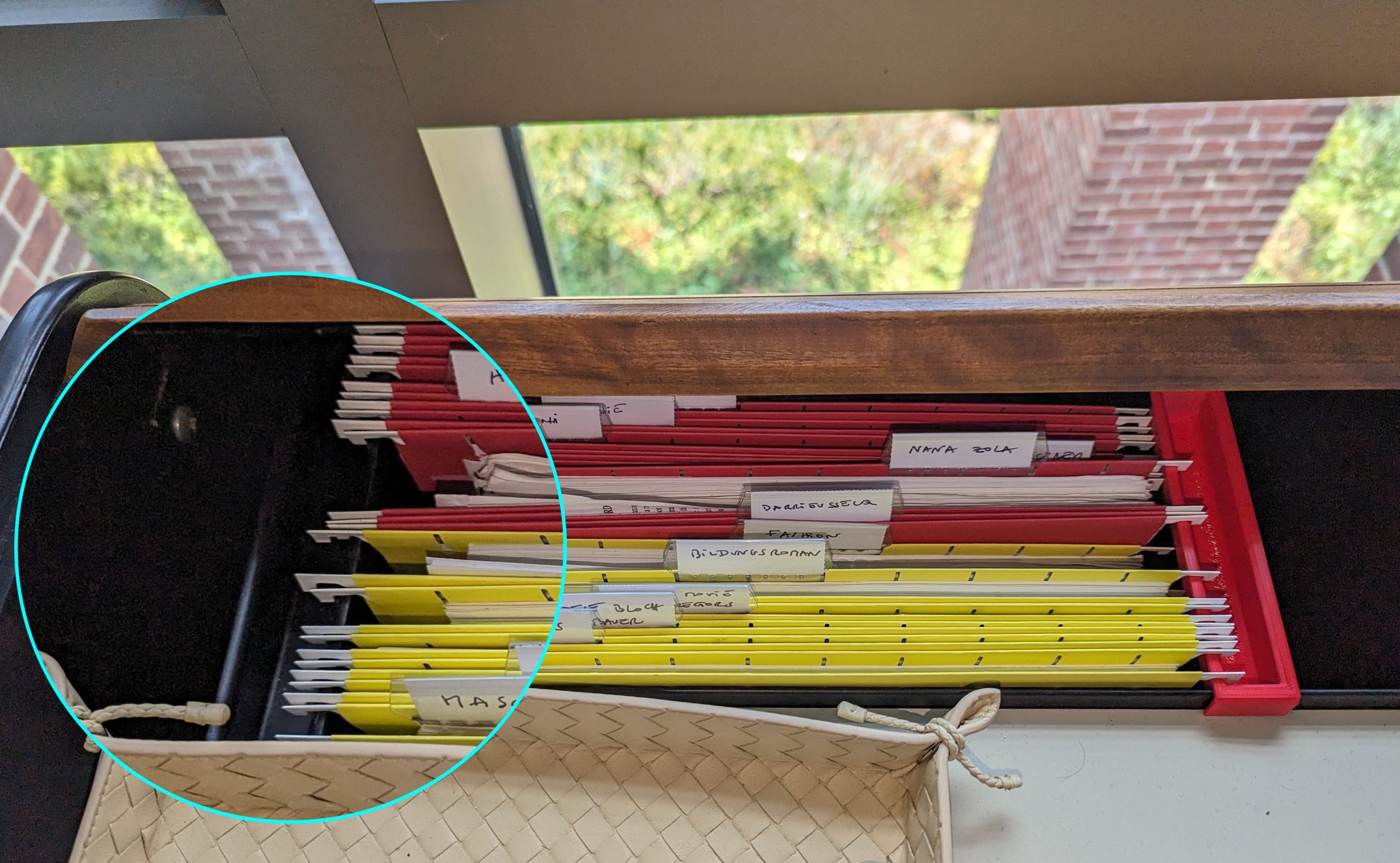
What sets this program apart is its access to an incredible network of resources, including the Makerspace, Fabrication Lab, and perhaps even parts of the interdisciplinary MakersWeb. These spaces foster collaboration and creativity, connecting students with over 20 unique workspaces across campus. It’s not just about the tools; it’s about the vibrant community of creators who inspire and support one another.

Students have the freedom to explore a wide range of mediums, such as:

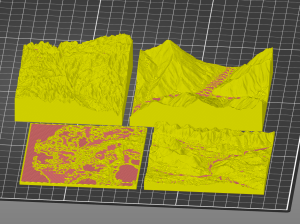
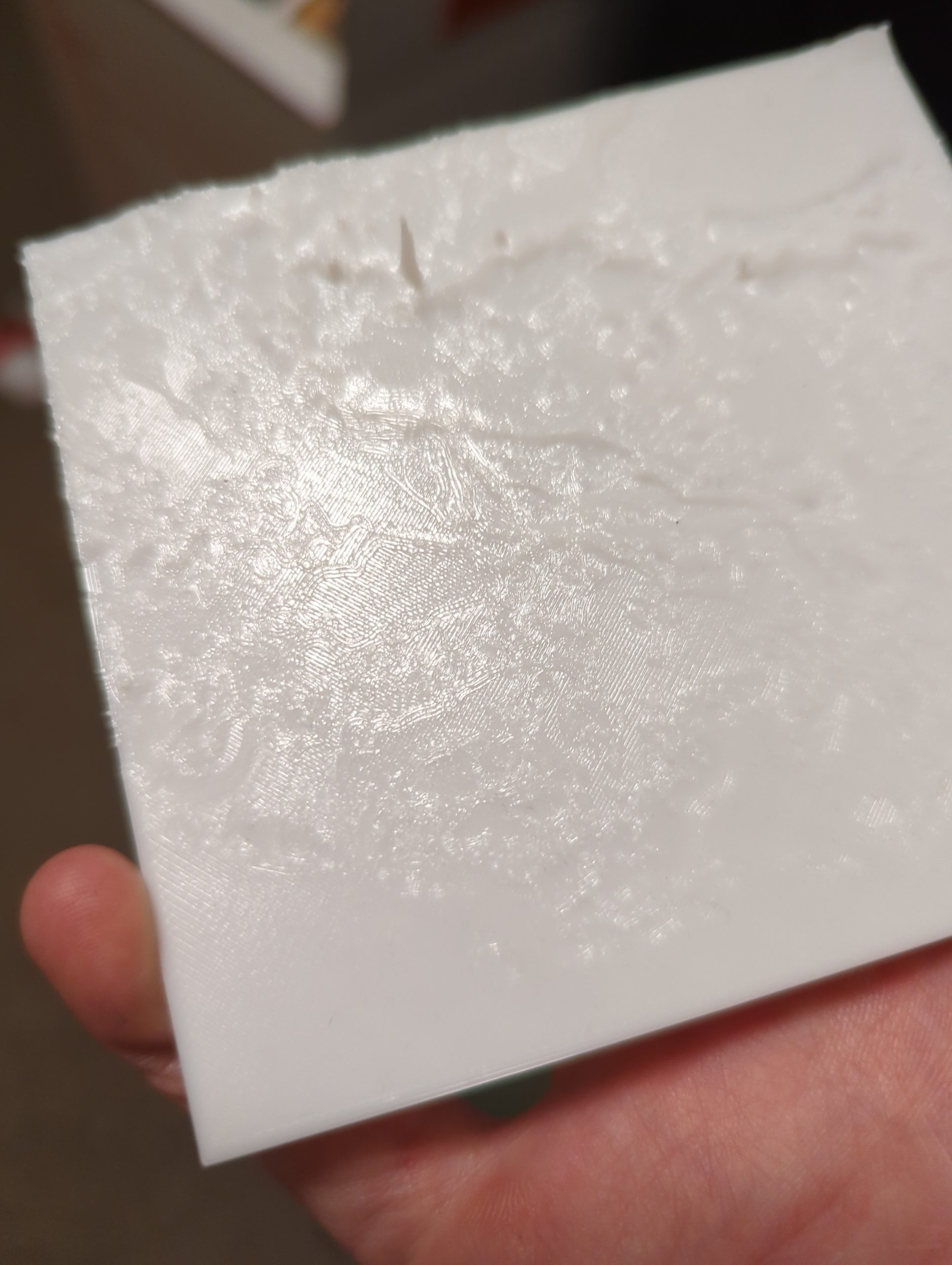
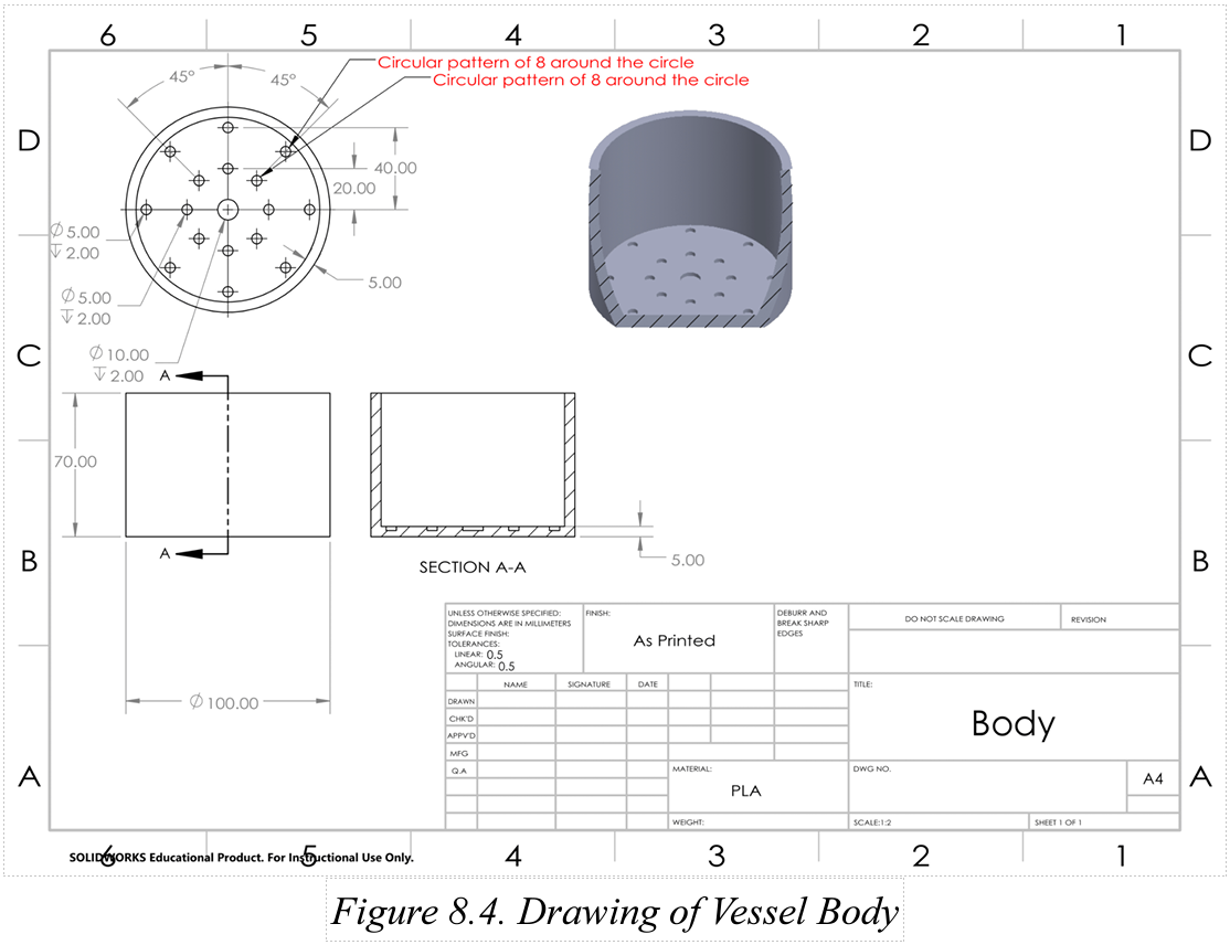
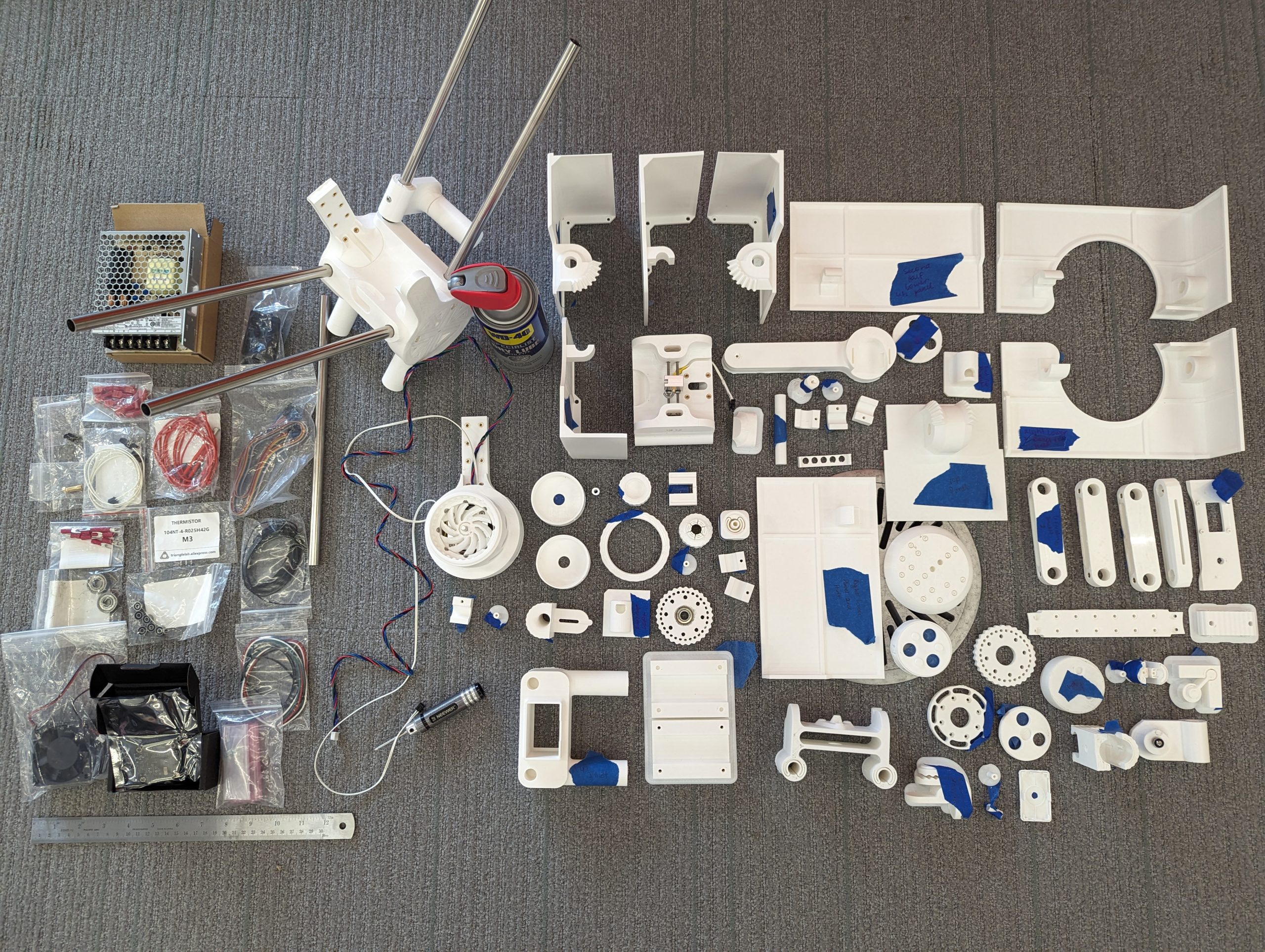
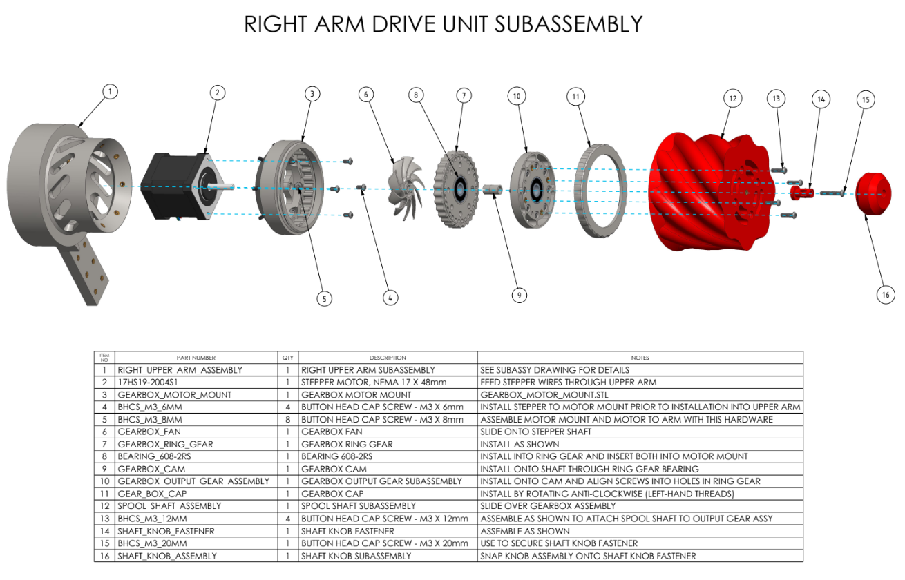
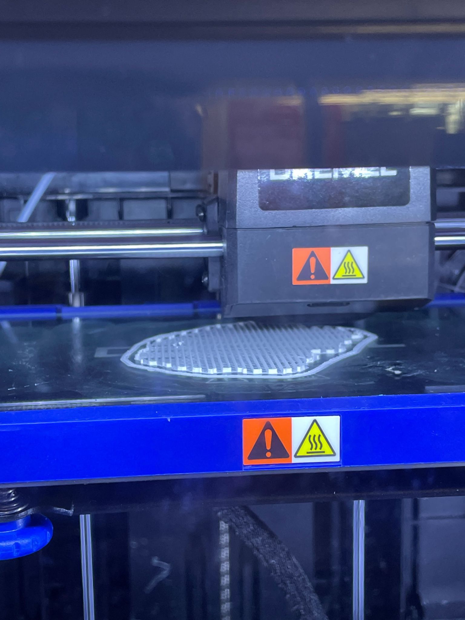
  • 3D Printing and Scanning: Create intricate designs or explore sustainable printing solutions.
  • Laser Cutting and Engraving: Add precision and detail to your projects with state-of-the-art technology.
  • Photogrammetry and Mold Making: Transform objects into digital models or design complex molds.
  • Fiber Arts: Try your hand at quilting, sewing, crocheting, or even experimenting with mixed textiles.
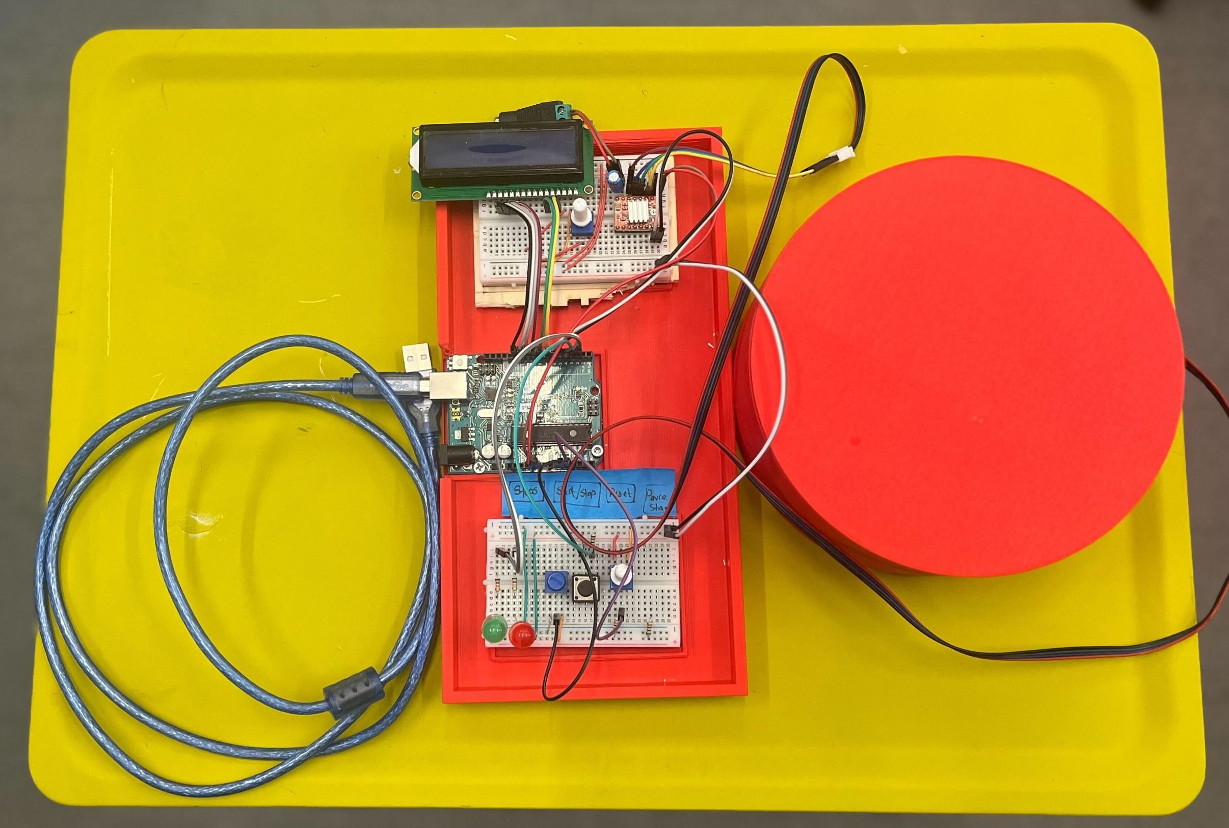
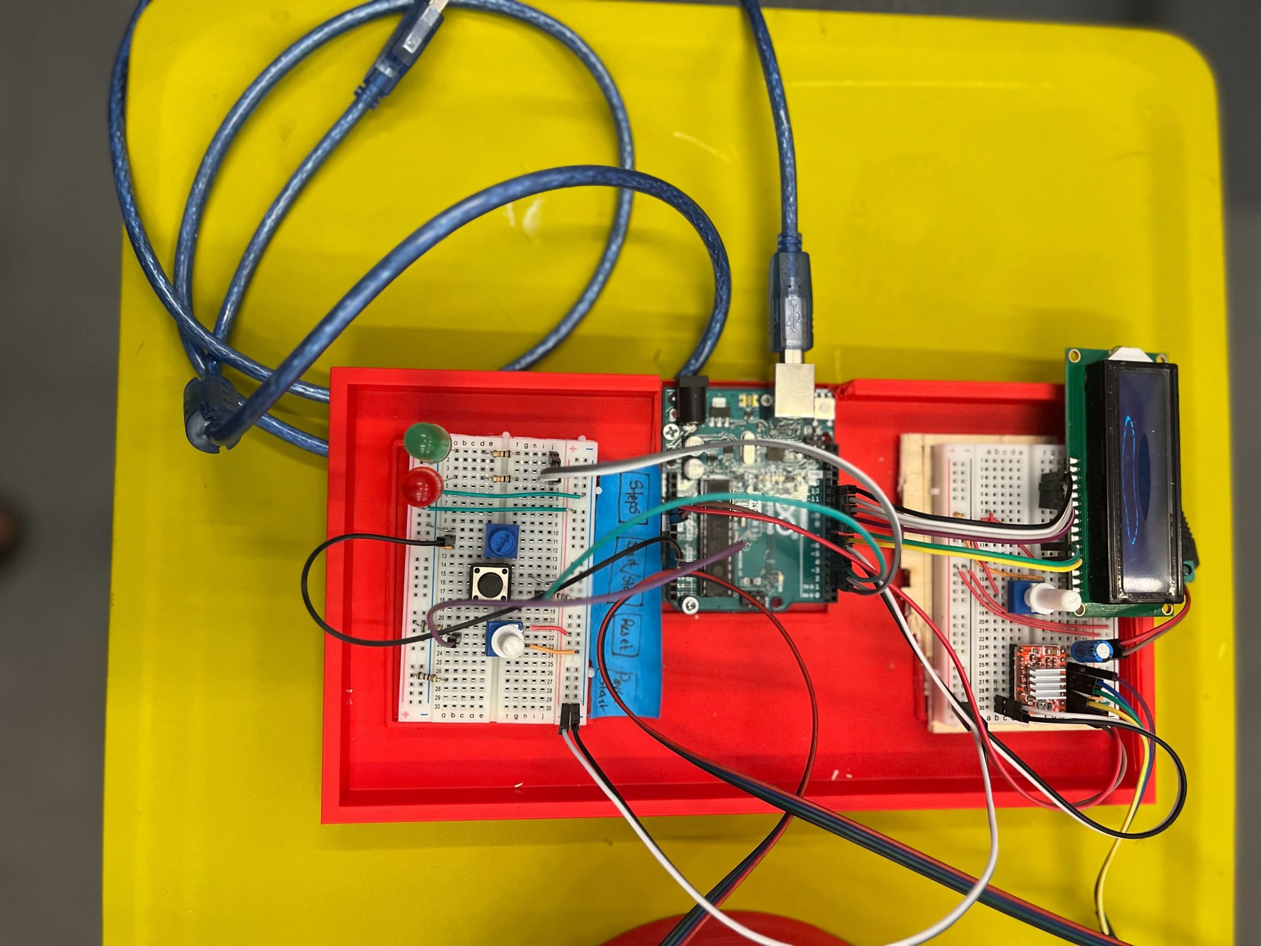
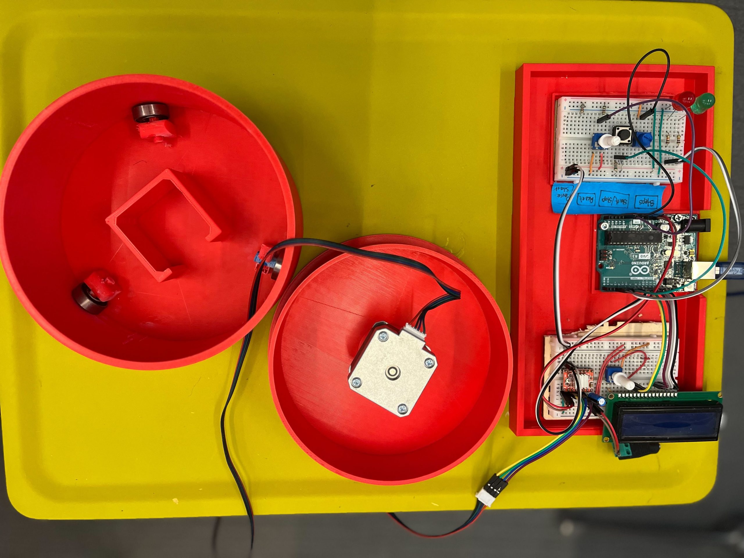
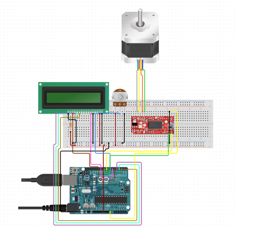
  • Microprocessor Prototyping: Build interactive devices using Arduino or Raspberry Pi.
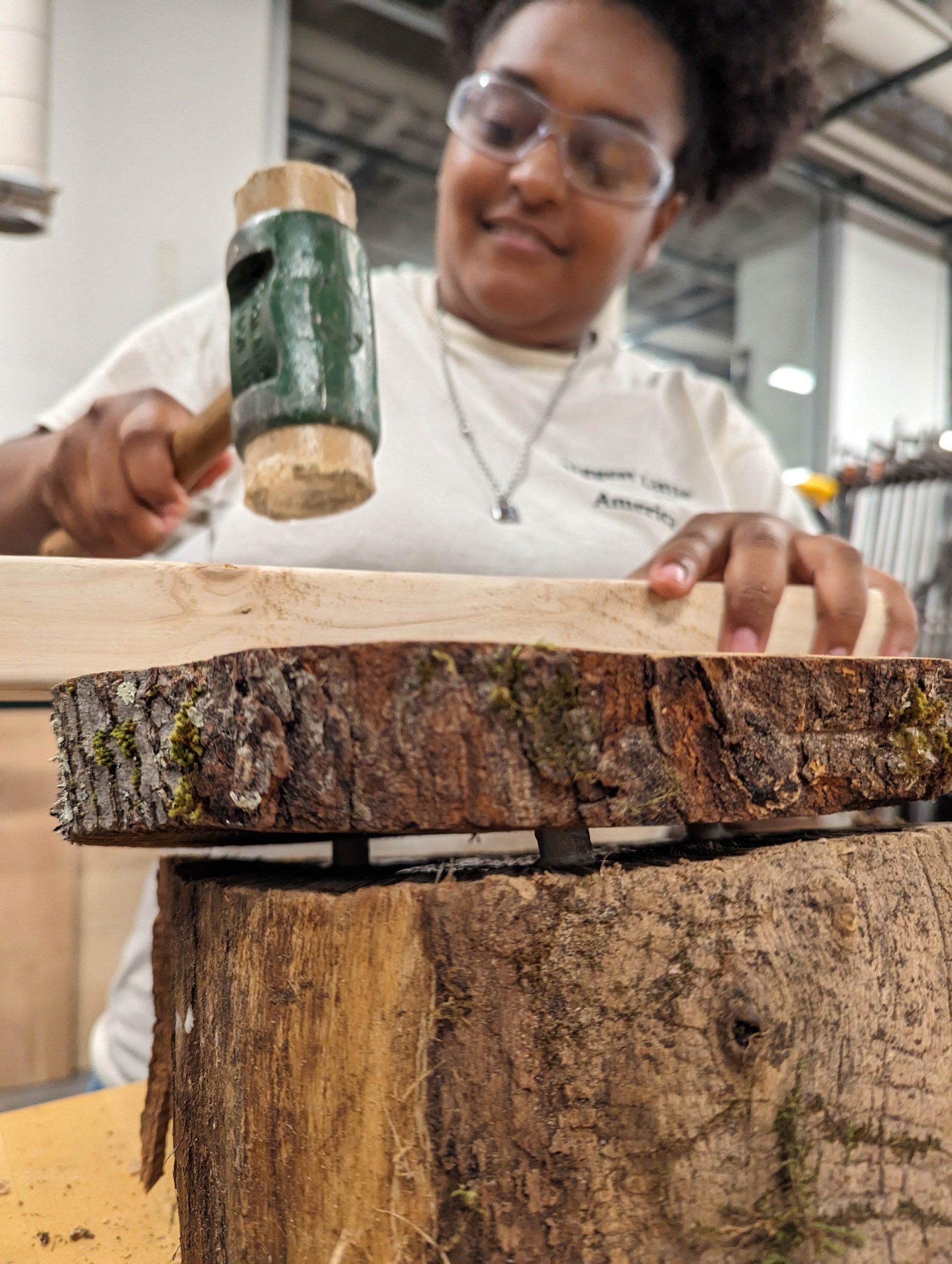
  • Woodworking and Cricut Cutting: Craft furniture, decor, or intricate designs with these versatile tools.

The Application Process: Turning Ideas into Reality

Getting started with the Senior Year Experience (SYE) is as straightforward as sharing your vision. The process is designed to be simple yet impactful, ensuring that every participant has the opportunity to fully explore their creativity. Here’s how it works:

1. Submit Your Idea

The journey begins with an email. Reach out to David Keiser-Clark, the Makerspace Program Manager, to pitch your project idea. Don’t worry if it’s still in the brainstorming stage. This is your chance to outline your vision, explain your goals, and share what excites you about your project. Whether it’s a sustainable solution, an artistic masterpiece, or a tech-driven innovation, the SYE is all about giving life to bold and unique ideas.

2. Collaborate and Create
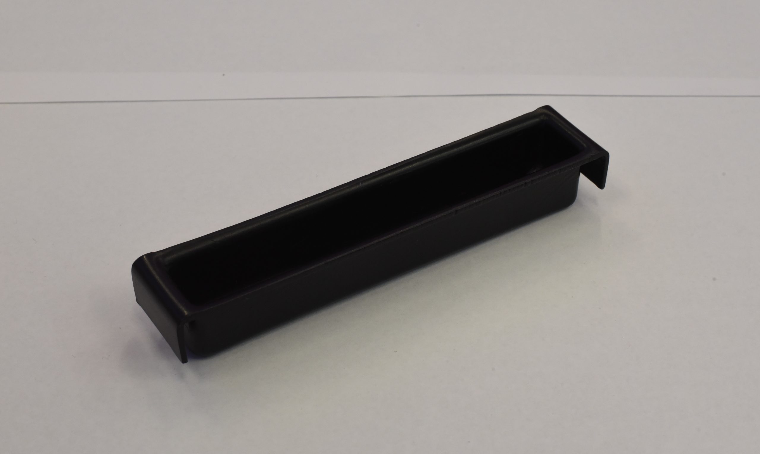
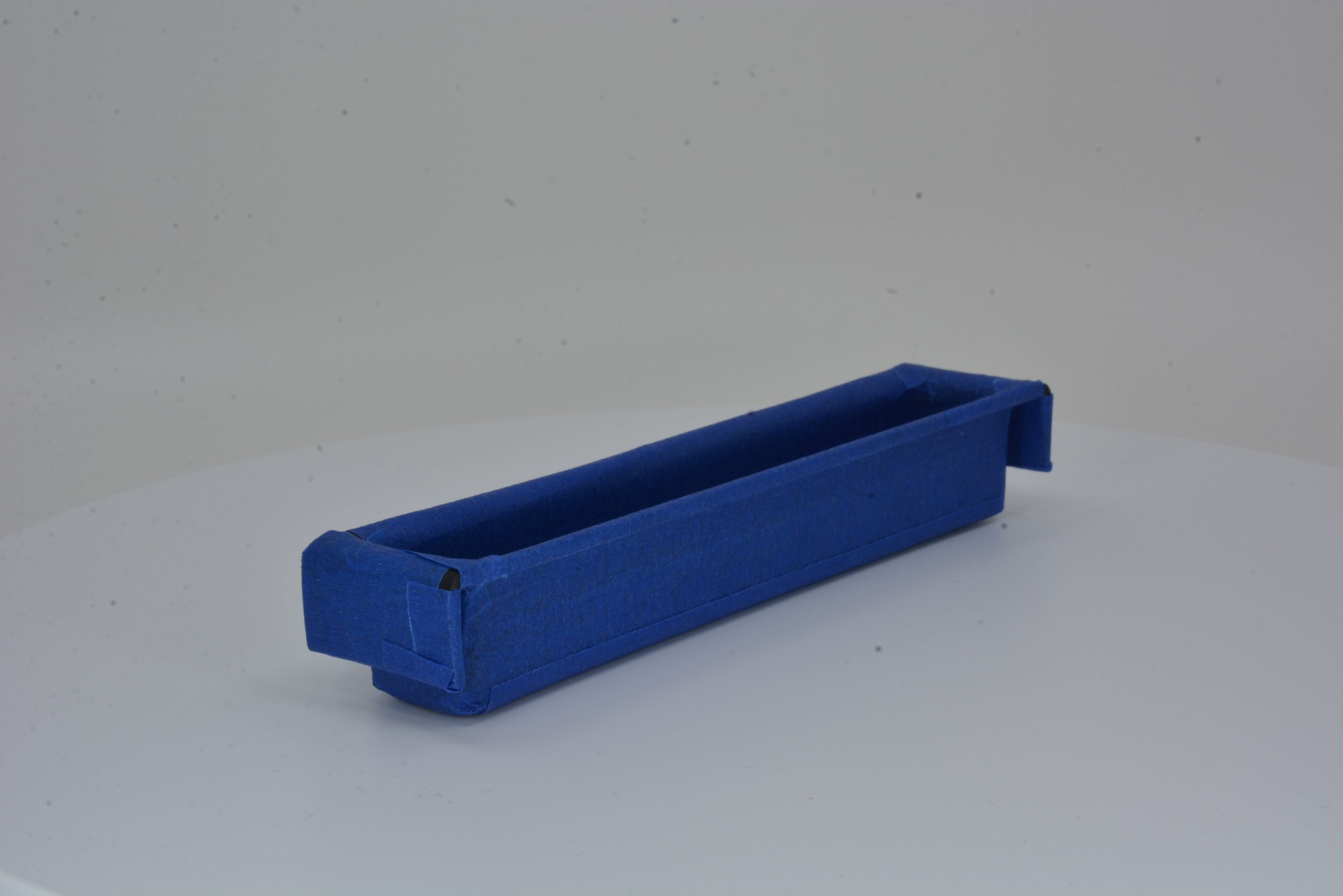
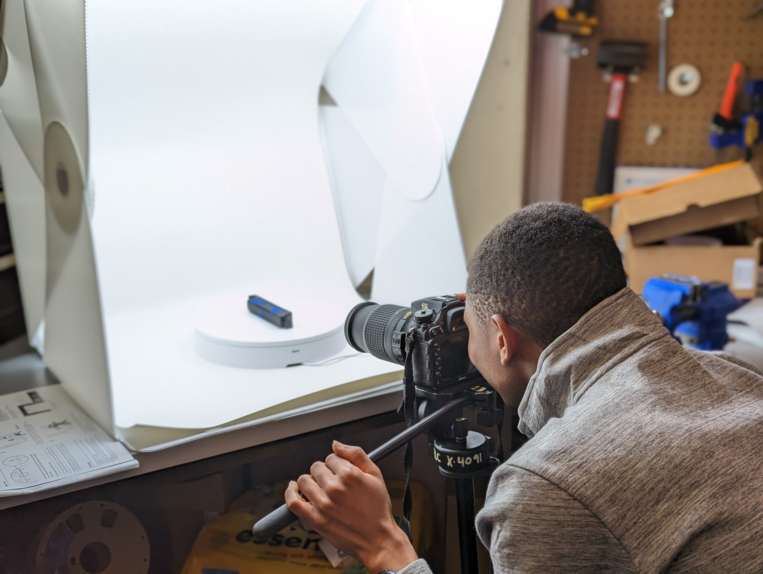
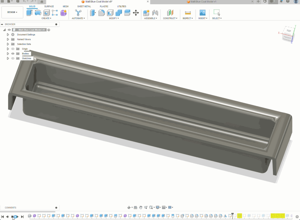
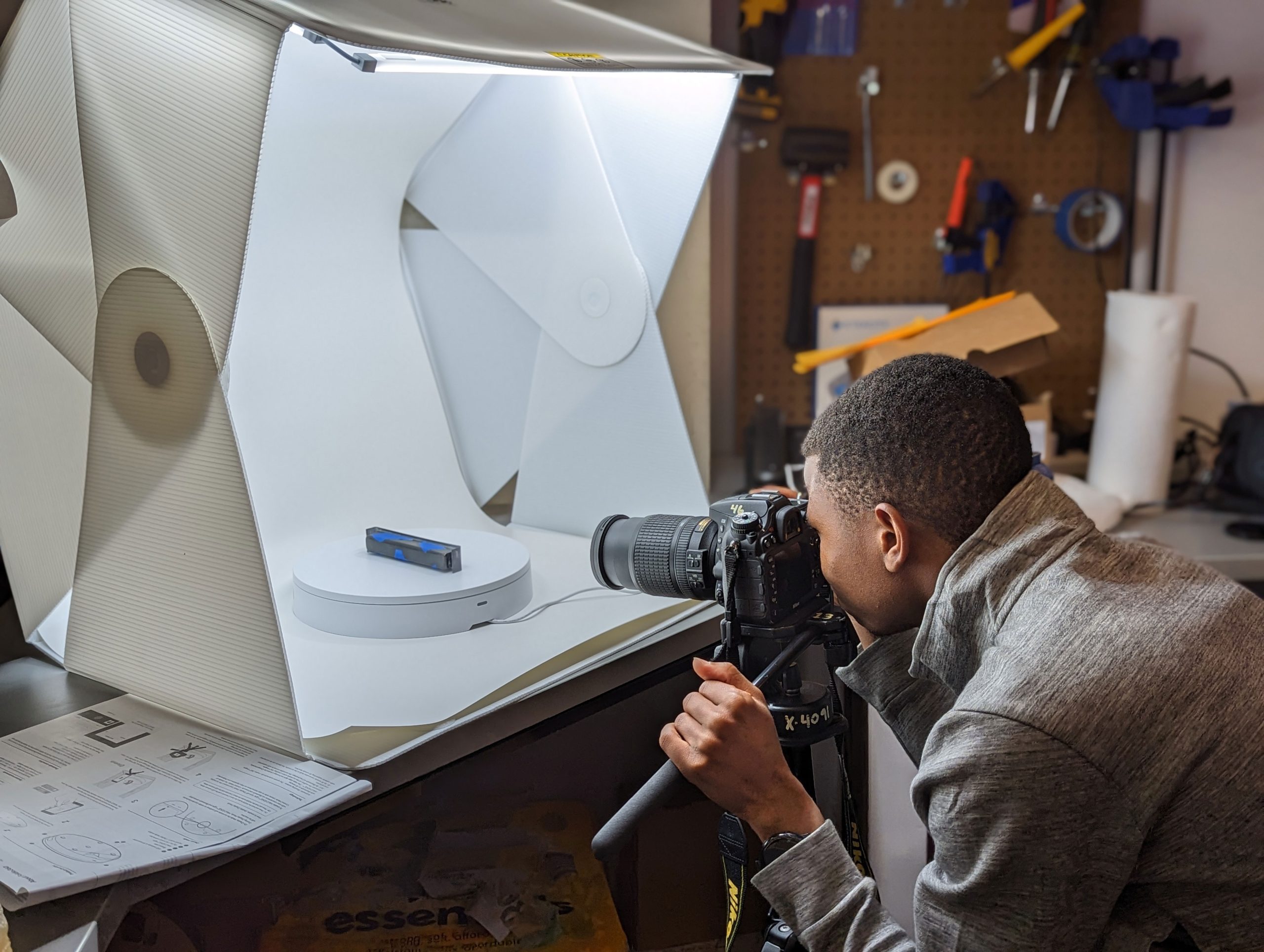
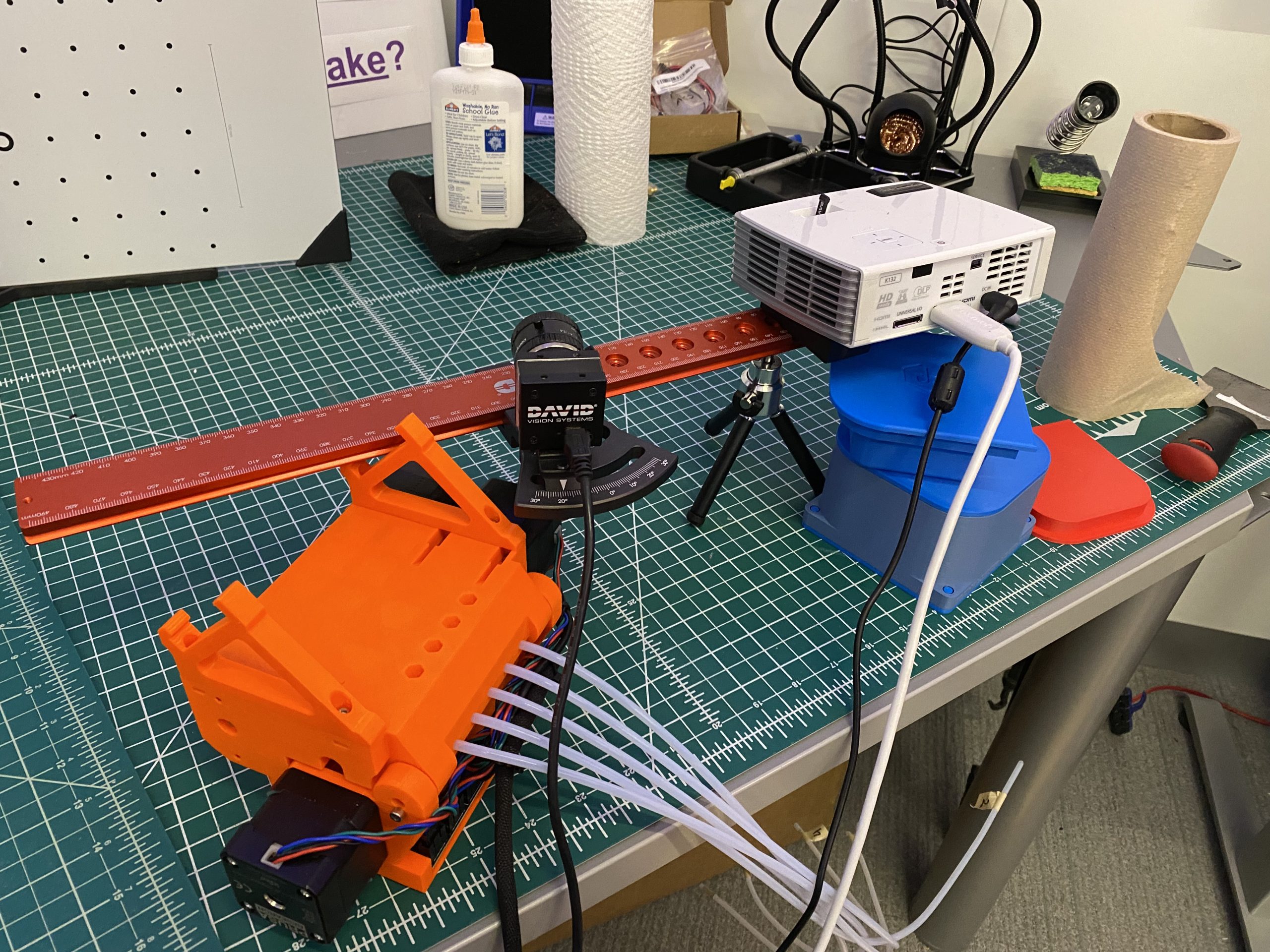
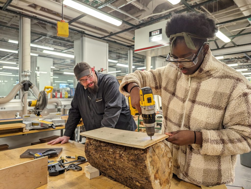
Once your project is accepted, you’ll dive into the creative process with the support of campus experts and access to state-of-the-art tools. From 3D printers and laser cutters to fiber arts tools and microprocessor kits, the Makerspace and Fabrication Lab have everything you need to bring your concept to life. You’ll also have the chance to collaborate with knowledgeable staff and fellow students, making the experience as enriching as it is productive.

3. Showcase Your Work

At the end of the semester, your project will take center stage. Whether it’s displayed at an exhibition or shared with the broader campus community, your work will inspire future innovation and creativity. Completing an SYE project isn’t just about the final product, it’s about the process, the lessons learned, and the mark you leave on the Williams community. You also will be offered an opportunity to amplify your work by writing a guest Makerspace blog post.

What You Need to Know

  • The SYE accepts up to five projects per semester on a first-come, first-served basis. This ensures each participant receives a personalized, focused experience.
  • Selected projects are matched with the expertise available on campus, ensuring the right guidance and resources are at your fingertips.

The application process is intentionally simple, giving you more time to focus on what really matters, creating something meaningful, innovative, and entirely your own. So, if you have an idea that’s been buzzing in your head, now’s the time to turn it into reality. The SYE is your platform; all you need to do is take the first step.

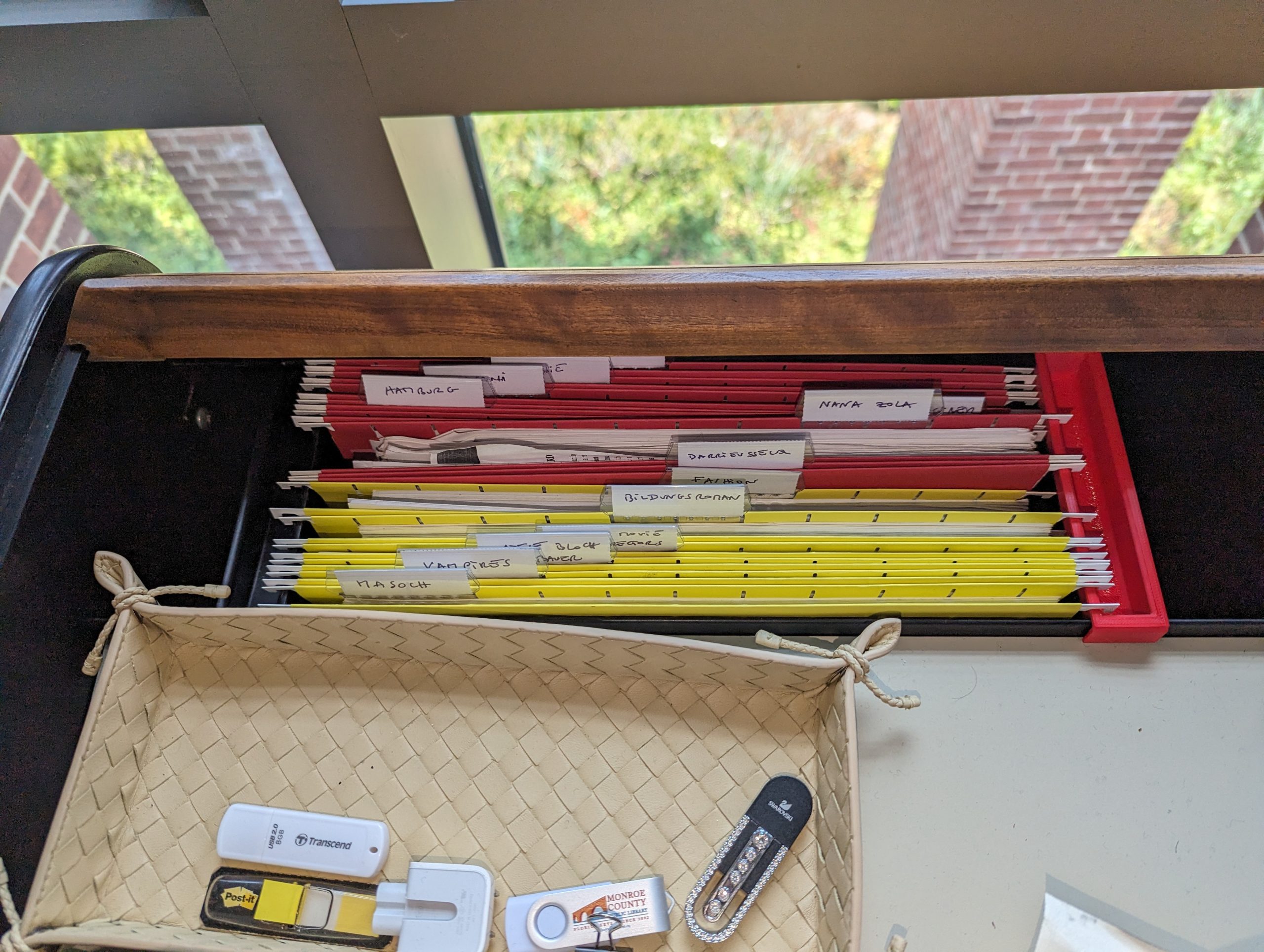
A Network of Campus Partners

The SYE thrives on collaboration, integrating support from campus partners like Alumni Engagement, Career S

ervices, the Zilkha Center, and more than a dozen others. These partnerships enhance the program’s impact, offering students a robust platform to refine their skills and showcase their achievements.

Leadership Behind the SYE

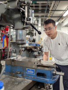
The Senior Year Experience (SYE) at Williams College was initiated under the leadership of Associate Dean Ray Grant, who serves as the Associate Dean for Senior Year Students and Director of Students in Transition. Dean Grant has been instrumental in shap

ing the SYE to provide seniors with meaningful opportunities to celebrate their achievements, explore new interests, and prepare for life after graduation. His dedication to student development ensures that the SYE remains a cornerstone of the senior experience at Williams. 

If the SYE had a superhero, it would be Dean Ray Grant: the guy who turned the “senior slump” into a launchpad for creativity and adventure. As the Associate Dean for Senior Year Students, he’s made sure the SYE isn’t just another check-the-box requirement but a once-in-a-lifetime chance to make your mark at Williams. His goal? Help every senior leave with stories, skills, and something awesome to show for their time here.

Why SYE Matters

Beyond creating something tangible, the SYE is about professional growth and personal fulfillment. Imagine presenting a digital portfolio of your project to potential employers, highlighting skills in research, design, and execution. Platforms like Wakelet and Bulb, recommended by the SYE team, provide seamless ways to compile and share these experiences.
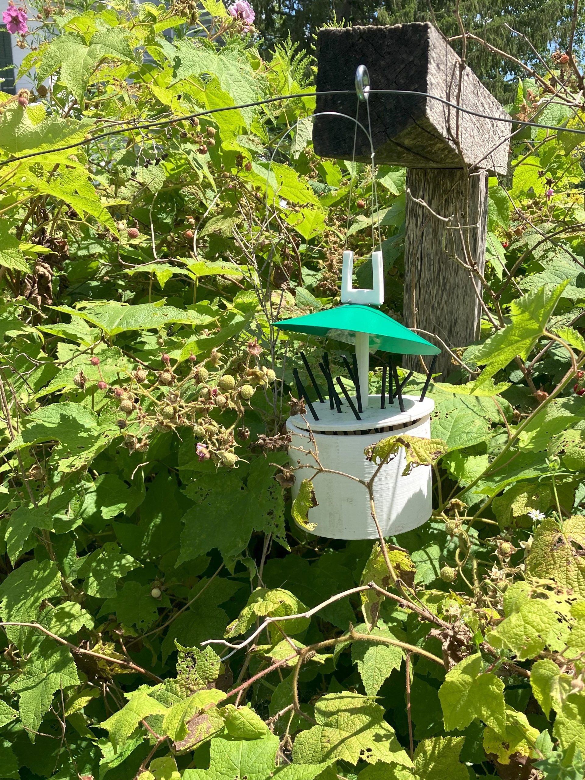
Inspiring Creations

The Makerspace has already facilitated awe-inspiring projects, such as:

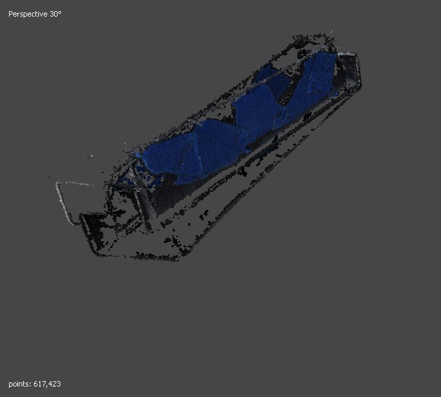
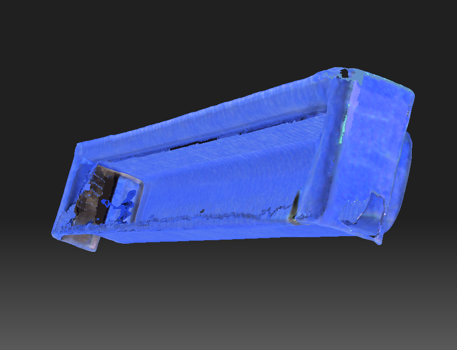
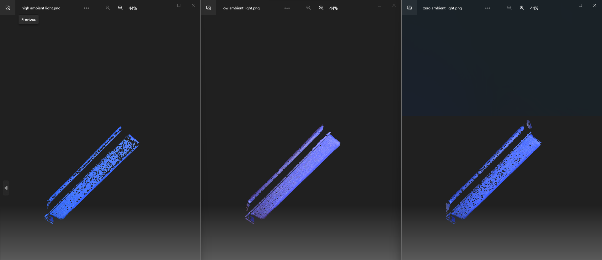
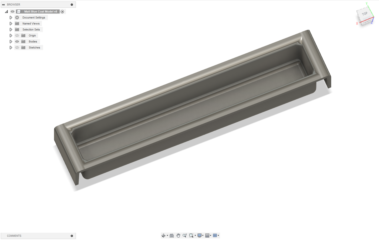
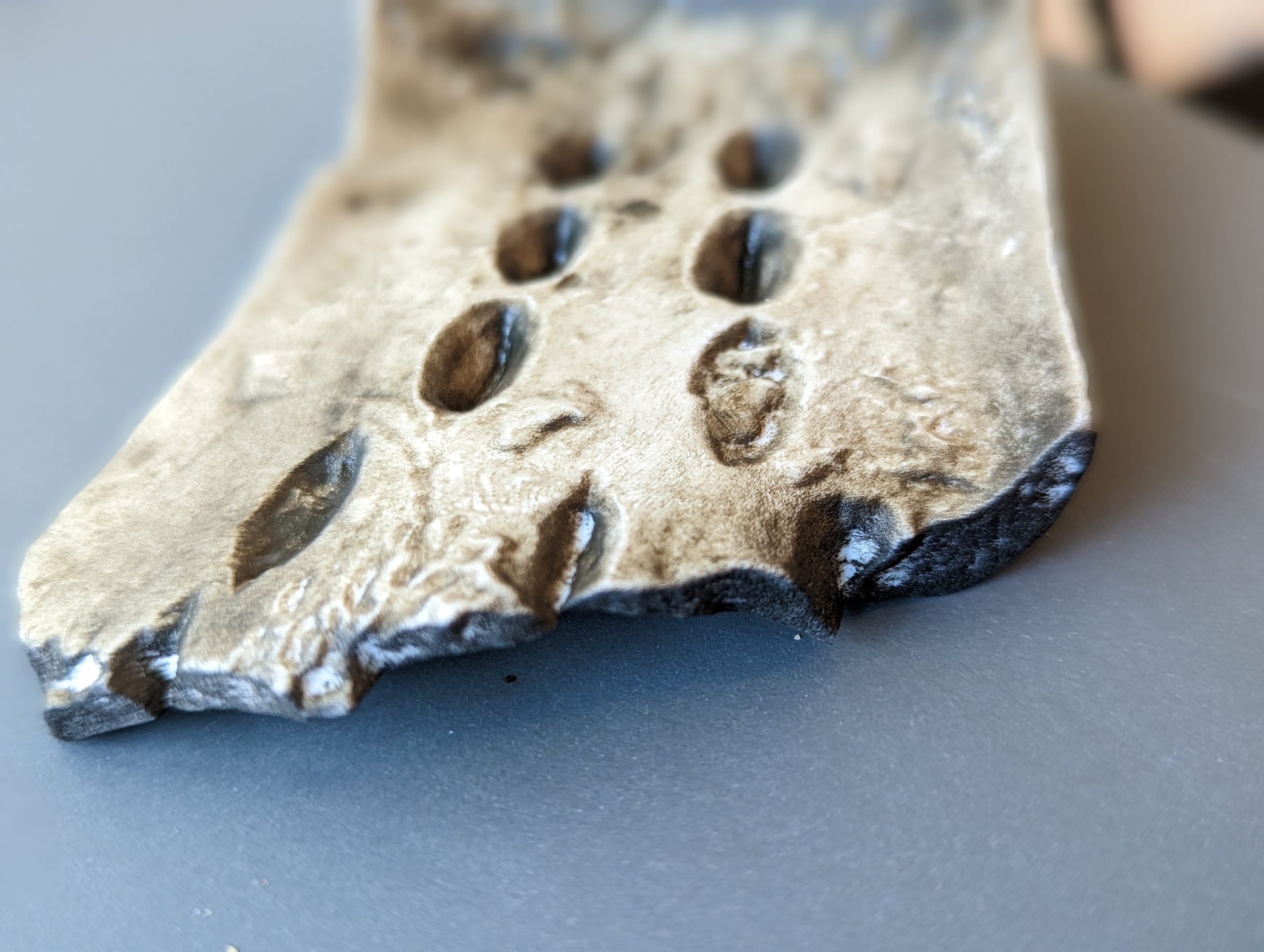
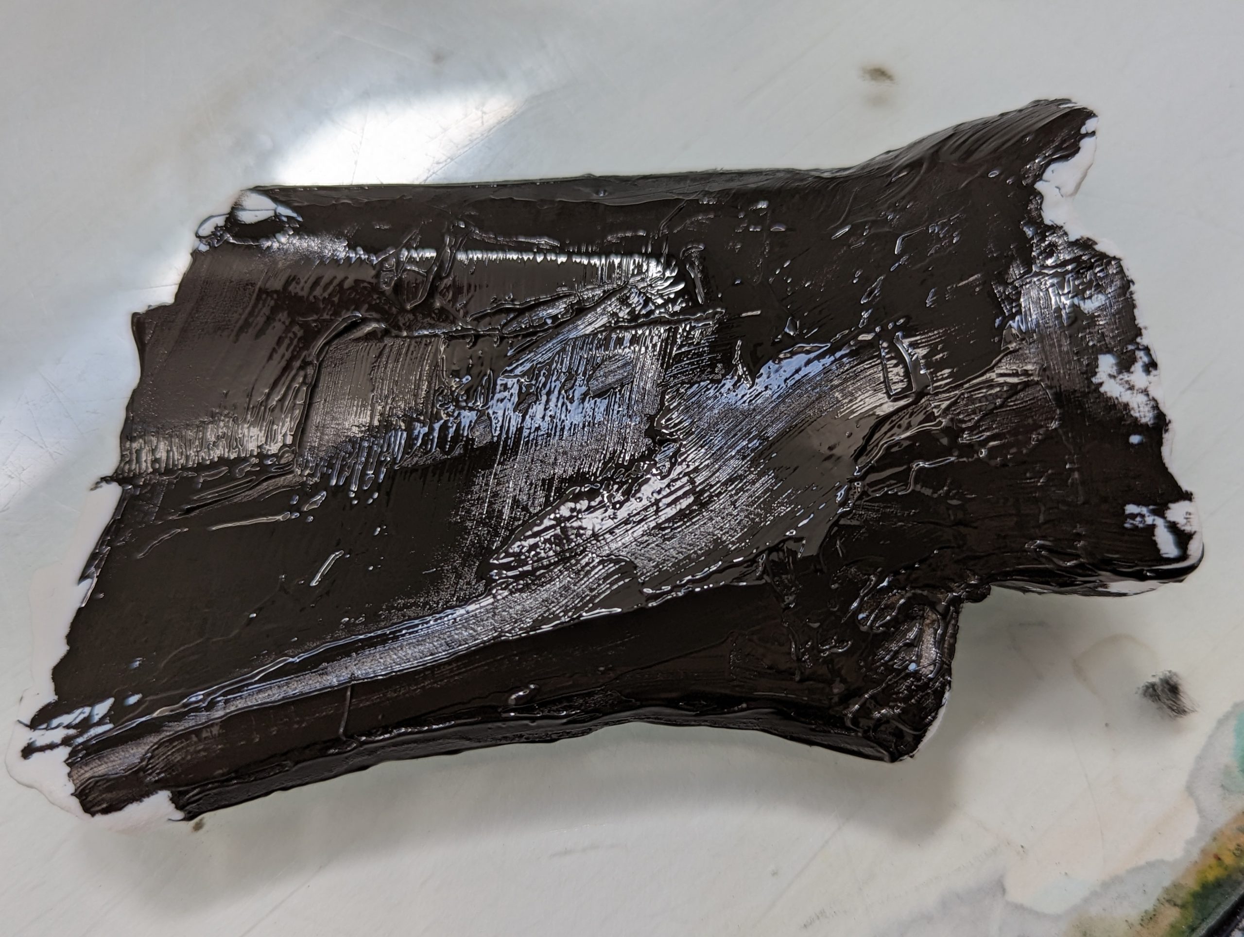
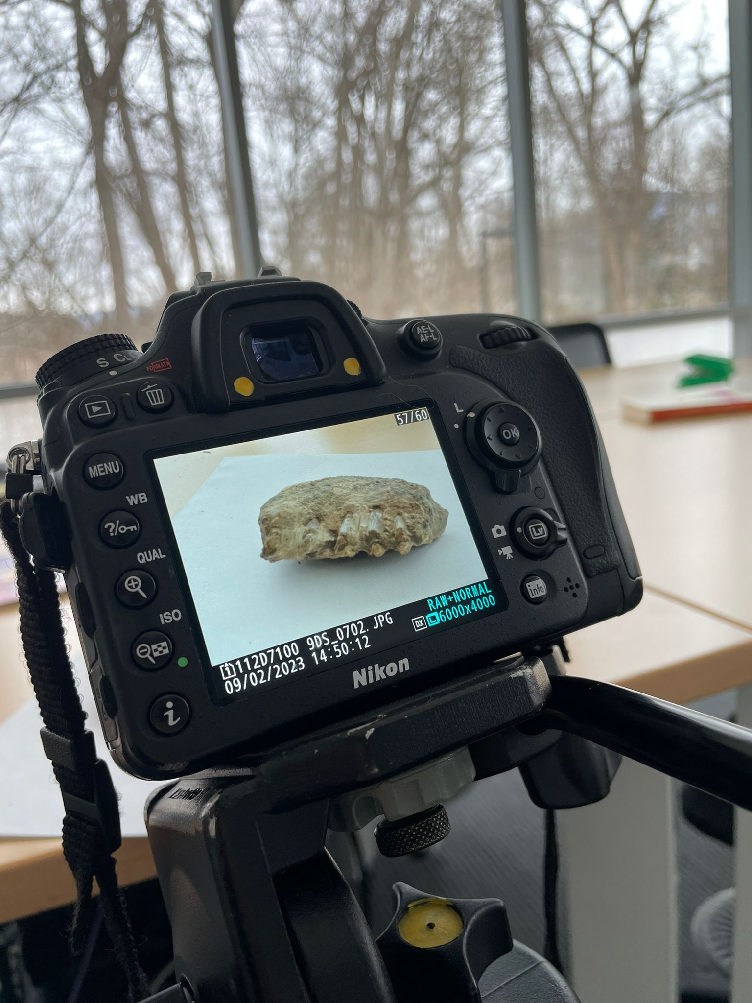
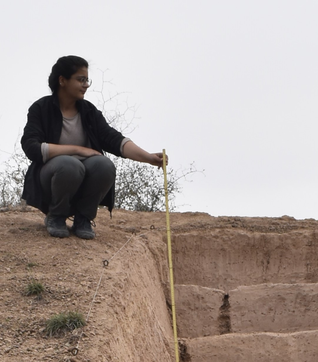
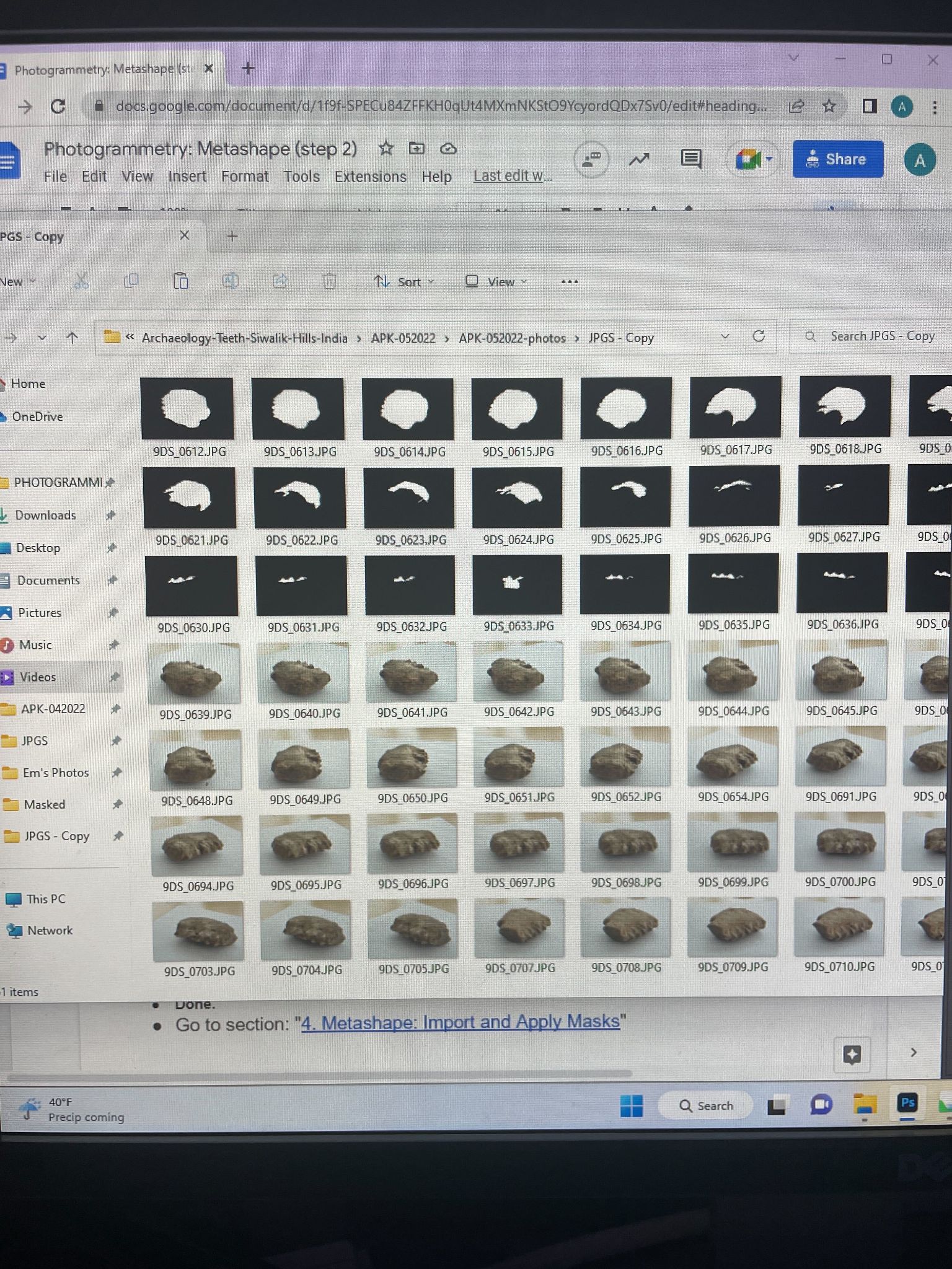
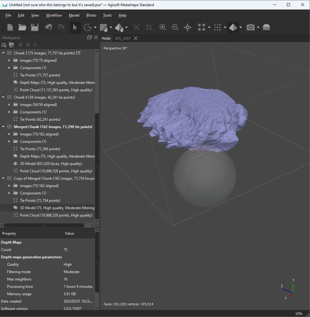
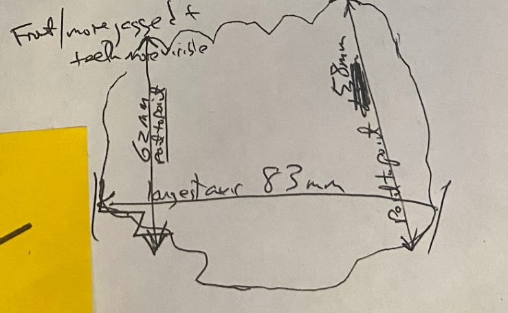
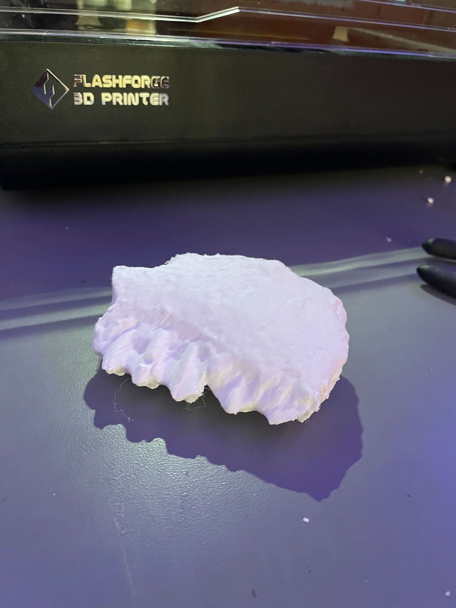
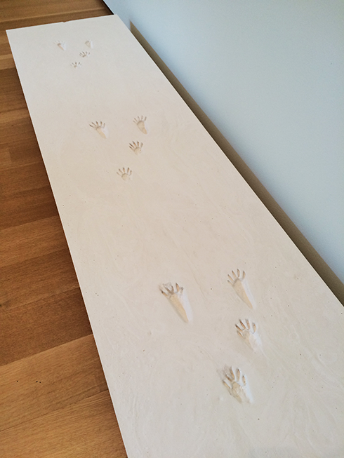
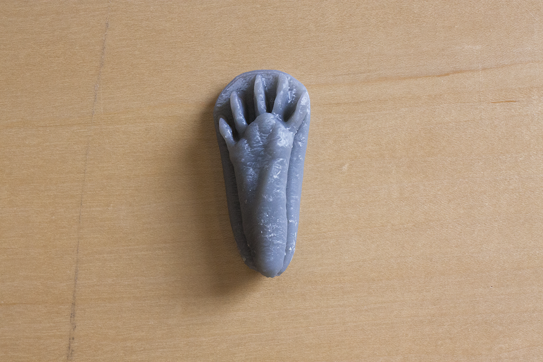
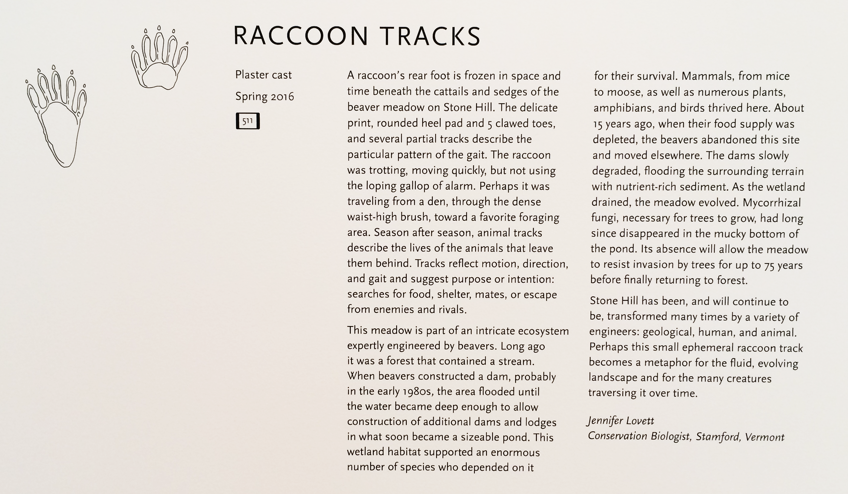
  • High resolution 3D photogrammetry scans of million year old Bovid teeth from an archeological site in the Siwalik Hills, India
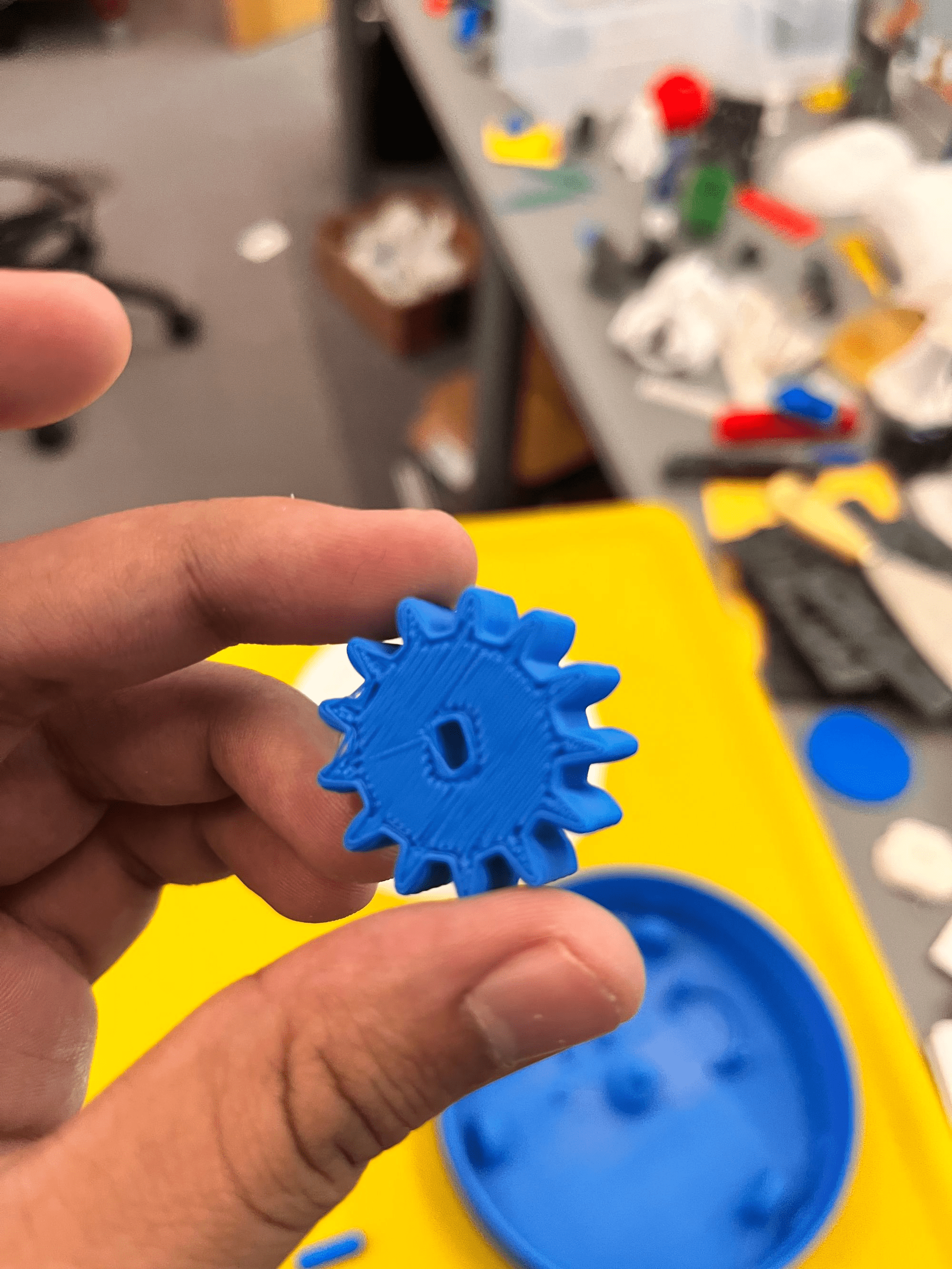
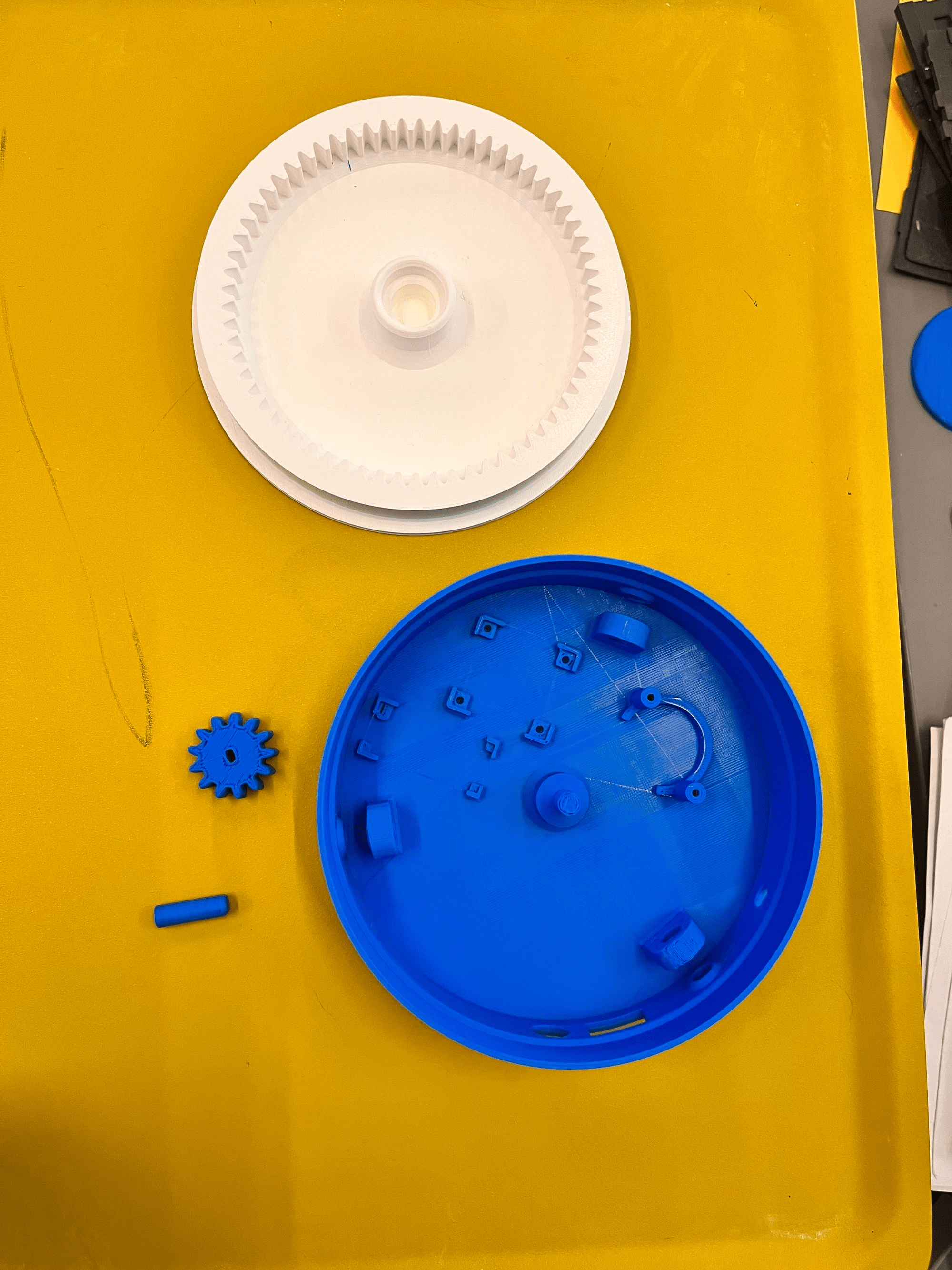
  • Extracurricular 3D-printed and painted board games like Catan
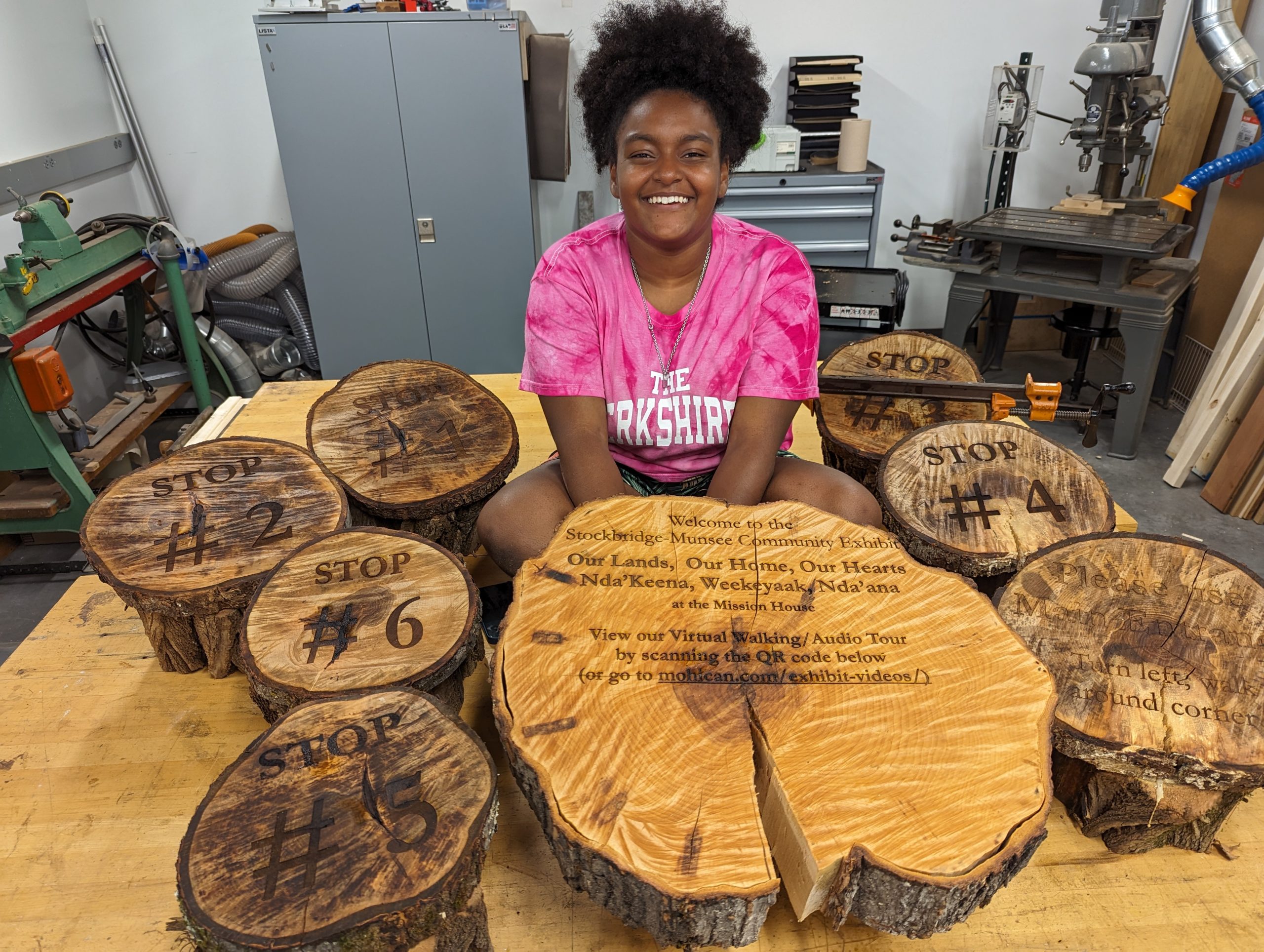
  • Sustainably harvested Hopkins Forest logs to laser-engraved garden signs for the Zilkha Center
  • Museum quality exhibition reproductions such as this Mayan Tenon (“monster” head)
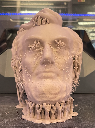
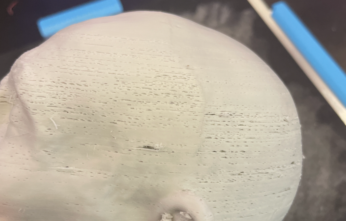
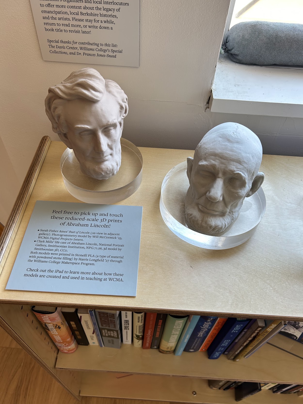
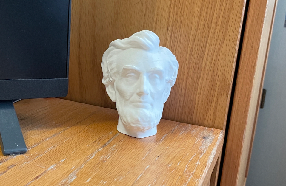
  • Lincoln life masks brought to life with 3D modeling

These creations demonstrate the blend of creativity and innovation that the SYE nurtures.

Happy applying!

Preserving History: How I used 3D scanning to preserve an ancient cuneiform tablet

I have always been someone who is interested in different languages. My passion sparked when me and my family moved to the United States from Venezuela, and I needed to learn English fast to help my family navigate this country, since they had less time to learn English than I did. Although I didn’t have an English tutor to formally teach me English, I taught myself most of my English through reading, which made me develop a love for languages in written form. Now, at Williams, I am a prospective Chinese Language major because I fell in love with the language after taking CHIN 101! So when I was given the opportunity to work on a project that was so related to my interest in languages, I jumped on it immediately.

Cuneiform is regarded as the earliest known writing system. These words are written into clay and then baked into a sturdy, but fragile tablet. I was also really surprised to learn that cuneiform was used to write several languages. I had the pleasure to work with When we got to work, I was filled with excitement, but also some anxiety about the unknowns. Anne Peale, a librarian that works closely with the college’s special collections. She taught me that this particular cuneiform tablet was (insert interview details here). She plans to use the 3D printed tablet for educational purposes, because the characters in the tablet are very legible and hold information about a person’s taxes. Not only would 3D printing the cuneiform tablet allow several iterations of it to be used outside of the special collections library, it also allows us to make the tablet bigger, which makes the writing a lot easier to read. I was really excited about all of this, and it honestly made me want to learn how to read this type of cuneiform!

When we got to work, I was honestly really nervous. I didn’t know what to expect. This project required a way to record the tablet’s intricate wedges and patterns in a way that makes the writing completely legible, so we decided to use the unfamiliar Creality scanner to 3D scan the cuneiform, digitizing it into a file form. In my opinion, the Creality software was really intuitive. It was fairly easy to connect it to the computer, and to figure out how to correctly configure the scan. The most challenging part of this project was figuring out how to scan the tablet in a way that fully recorded the writing. We had some challenges with this, as the most detailed scanning mode included stickers that told the scanner its location, and since we couldn’t place the stickers on the cuneiform, we had to place them in its perimeter, something that became really hard to deal with when we began to turn the scanner sideways to get the sides of the tablet, since it could no longer recognize the stickers due to the angle change. Another challenge we had was that the tablet was really hard to place in a balanced way that didn’t topple over, so we ended up putting a small weighted cushion to hold it up.


Since we couldn’t place the tablet in a way that was possible for us to capture all four sides in one scan, we had to do a scan for each of all four sides. Each side of the tablet took about twenty minutes to complete, and the Creality scanner is really heavy! Anne and I had to take turns scanning, and we were both so sore! Creality records 3D items by scanning each and every point on the item, and this tablet was so intricate that it had over a million points for each side! The more we scanned, the fewer points that were recorded, so we had to go around the item a lot slower and with a lot more complex angles to make sure we recorded every character.

After two hours, all sides were scanned. Now, the only thing that was left was to find a way to merge the different scans into the composite model of the tablet. Although the Creality software comes with a scan merging option, this did not work on our scans, so blender was used to merge it.

After a month, the 3D scanned cuneiform was ready! It was a lot bigger than the tablet, and a lot less fragile, and best of all, we now had a file that could be used for printing as many of these tablets as we want! I was really excited because it was also my first time getting to see a 3D scanned object up close, as well as hold it.

One side of the tablet is clearer than the other, so we are going to reprint the file as a resin print, because the material may help to raise the clarity of the 3D print. 

Working on this project was a true journey of growth for me. The complexity of 3D scanning and the delicate nature of the cuneiform tablet made every step a learning experience. There were moments when I felt challenged, uncertain about the technical aspects or the best way to handle the fragile tablet. But with each hurdle, I gained more confidence, honed my problem-solving skills, and improved my ability to think creatively under pressure. I have always been really interested in languages, and this project sparked an interest in the digital humanities and language preservation.The potential of 3D scanning in the field of digital humanities is endless. From preserving endangered artifacts to making them accessible to scholars and students around the globe, this technology ensures that history is no longer bound by geography or fragility. I couldn’t help but think, what other treasures could we preserve this way?

Studying Savannah Sparrows on Kent Island

The Williams lab studies Savannah sparrows (Passerculus sandwichensis), small migratory songbirds that live in grassy fields across North America (Cornell Lab). Savannah sparrows have been the subject of a long term study at Bowdoin College’s field research station on Kent Island in New Brunswick, Canada. 

The Kent Island research station. Cabins and the main building are photographed from the field designated for Savannah sparrow, herring gull (Larus argentatus), and tree swallow (Tachycineta bicolor) research. (Photo credit: Dan Mennill)

The Kent Island research station. Cabins and the main building are photographed from the field designated for Savannah sparrow, herring gull (Larus argentatus), and tree swallow (Tachycineta bicolor) research. (Photo credit: Dan Mennill)

The Kent Island research station. Cabins and the main building are photographed from the field designated for Savannah sparrow, herring gull (Larus argentatus), and tree swallow (Tachycineta bicolor) research. 

Savannah sparrows have been recorded on Kent Island since the 1960s and their songs have been recorded intensively since 1980 (Williams et al., 2018). Clara Dixon, who thoroughly recorded songs in 1980 and 1982, inspired a continued in-depth study of Savannah sparrows to this day because their songs are an excellent model for studying cultural evolution, the socially learned traits of populations change, and the bird song learning has parallels with the development of human speech (Williams et al., 2022). Male Savannah sparrows learn components of their songs from various tutors, including their biological father, social father, and both hatching and breeding-year neighbors. They then use these songs to attract mates and defend their territories.

Savannah sparrow on Kent Island. A key characteristic to help identify these birds are their distinctive yellow plumage above the eye, as shown in the photo. (Photo credit: Dan Mennill).

Savannah sparrow on Kent Island. A key characteristic to help identify these birds are their distinctive yellow plumage above the eye, as shown in the photo. (Photo credit: Dan Mennill).

Professor Heather Williams first went to Kent Island in 1973, her first year of college. She has maintained her connection to the island, and realized the potential to contribute to the Savannah sparrow research by studying a local population in Williamstown since 2005. Birds are systematically color-banded—given a unique three band color combination on their legs so that they can be identified with binoculars—and their songs are recorded. In addition to analyzing songs, observing birds’ responses to variations in note count and spacing in songs is valuable for understanding which factors drive changes in song traits over time. To study birds’ reactions, our lab conducts playback experiments, which entail placing a speaker in the middle of a bird’s territory, playing stimuli of songs with either variable note spacing or note type, and recording a bird’s response. 

Example song from N.YR.

Example song from N.YR.

Birds may sing an additional ‘chuck’ note in either an earlier or later interval, variable spacing between x notes, and other soft notes that fall between the introductory notes. Last summer, we investigated what drives the changes in the occurrence and number of chuck notes in songs, and how the spacing of x and other notes may influence a bird’s reproductive success.

Henry Alexander '27 and Prof. Heather Williams in the field on Grand Manan, New Brunswick, Canada. Both Williams and Alexander carry microphones used to record bird songs. (Photo credit: Hannah Cumming)

Henry Alexander ‘27 and Prof. Heather Williams in the field on Grand Manan, New Brunswick, Canada. Both Williams and Alexander carry microphones used to record bird songs. (Photo credit: Hannah Cumming)

Birds typically seek out the source of the song in a playback study. Placing a fake bird near a hidden speaker can enhance a playback because the bird directs its behavior towards the specific target. Taxidermy Savannah sparrows have been used in such experiments, but as Professor Williams warned us throughout the summer, they do not last long. The real birds aggressively attack and eventually destroy that type of model. 

We asked the Makerspace to 3D print a durable bird that we could repeatedly use in these playback experiments. The students brought a free 3D model of a Song Sparrow to Alice Sore ’27, a Makerspace student worker, since it was similar in appearance to the Savannah Sparrows we study. Using Blender, Alice modified the model by removing the legs, which would have been too fragile to print and nearly impossible for the bird to balance on. She replaced them with a simple base that could be hidden among leaves or grass in the field. After an initial failed print, Alice successfully produced two near-perfect models, which were then handed over to our lab for painting. A member of our lab, Hannah Cumming ’28, who is a prospective Biology and Studio Art double major, painted the models to match a Savannah Sparrow’s typical plumage. A member of our lab, Hannah Cumming, who is a prospective Biology and Studio Art double major, then painted the model to match a Savannah sparrow’s typical plumage. We gave our two painted models an imaginary three-band color combination as their name, choosing B.OG (Black band on the left leg, Orange band over Green band on the right) for one, and GO.B (Green band over Orange band on the left leg, Black band on the right) for the other. The names were inspired by the amazing peatland environments on Kent Island. 

3D printed Savannah sparrow model created by the Makerspace. Our lab painted this bird to use in our field experiments.

3D printed Savannah sparrow model created by the Makerspace. Our lab painted this bird to use in our field experiments.

B.OB, a Williamstown bird, demonstrates our color-banding system. He has Black over a US Fish and Wildlife Service aluminum band on his left leg, and Orange over Black on his right leg (from the perspective of the bird). (Photo credit: Hannah Cumming)

B.OB, a Williamstown bird, demonstrates our color-banding system. He has Black over a US Fish and Wildlife Service aluminum band on his left leg, and Orange over Black on his right leg (from the perspective of the bird).  (Photo credit: Hannah Cumming)


B.OG, like some of his living and wild counterparts, migrated to Canada with our lab this summer to spend time on Kent Island. We used the model bird in playback experiments to test female responses to song variations. We placed B.OG in the mown path in the middle of a territory and hid the speaker nearby in taller grass. We then conducted the playback experiment to see whether females would respond aggressively to the songs or with intrigue. Approaches without aggression by a female would indicate that certain song traits are “sexier,” meaning the trait improves a male’s reproductive fitness. An aggressive approach would indicate that female choice is not driving changes in this song trait.

Kate Swann (‘26, left) and Hannah Cumming (‘28, right) excitedly preparing to conduct playback experiments on Kent Island. (Photo credit: Ian Kyle)

Kate Swann (‘26, left) and Hannah Cumming (‘28, right) excitedly preparing to conduct playback experiments on Kent Island. (Photo credit: Ian Kyle)

Due to the timing of our experiment, females were feeding their nestlings and did not respond to the songs or birds. Due to the timing of our experiment, when females were actively feeding their nestlings, they did not respond to the songs or birds. This highlighted for us the importance of seasonal timing in behavioral experiments.

We later used GO.B to test male responses in Williamstown. We placed the 3D printed model on a stake in the meadow and played songs to stimulate birds’ responses. Subjects flew around the model and treated it the same as live birds also sitting on posts: the subject approached the bird (whether live or 3D printed), and when it did not fly away, the subject returned to its original post.

This project also taught us how interdisciplinary collaboration between biology and technology can open up new methods for fieldwork. Our lab is excited to continue using the model birds in future research projects! In the future, we hope to expand the use of these models to test additional song traits and to explore how responses vary across seasons and populations.

B.OG perched on a Kent Island tree. We used this 3D printed and painted model to test female responses to song variations on Kent Island. (Photo credit: Heather Williams)

B.OG perched on a Kent Island tree. We used this 3D printed and painted model to test female responses to song variations on Kent Island. (Photo credit: Heather Williams)

B.OG analyzing his fellow birds’ songs, shown in the background. (Photo credit: Henry Alexander)

B.OG analyzing his fellow birds’ songs, shown in the background. (Photo credit: Hen

Kate Swann presented her research at the Summer Science Research Poster Session on August 8, 2025

Kate Swann presented her research at the Summer Science Research Poster Session on August 8, 2025

Works Cited

Cornell Lab or Ornithology. (2025). Savannah sparrow in All about birds. Cornell University. https://www.allaboutbirds.org/guide/Savannah_Sparrow/overview

Williams, H. et al. (2018). The buzz segment of Savannah sparrow songs is a population marker. Journal of Ornithology 160, 217-227.

Williams, H. et al. (2022). Cumulative cultural evolution and mechanisms for cultural selection in wild bird songs. Nature Communications 13, 4001.

3D Printed Topographical Maps of Louisiana, Bhutan, and the Berkshires!

Arriving in the Berkshires

I arrived at Williams as a freshman never having visited the campus. Despite the admissions webpage’s best efforts to warn me, I was still shocked by the beauty of the mountains. Various trips to Pittsfield and Albany, mountain day hikes, and other excursions took me outside the main campus, but I couldn’t keep track of all the mountains, and I had little to no sense of the Berkshire geography. I put off looking closely at a map to orient myself because I kept thinking this would all be so much easier if I could just run my fingers over a topographical map of the area.

Creating Meaningful Gifts

Last semester, I decided that a 3D printed map of Williams would make a nice gift for my friends who were graduating. And, with the help of the website https://touchterrain.geol.iastate.edu/ and David Keiser-Clark at the makerspace, I made it happen. It was actually pretty easy. Touchterrain let me trace out the area I wanted a map of and download the elevation data as an STL file, which I sent to David, who got it printed.

The Process

When I first came to the Makerspace with an STL file of the Williams College campus, my goal was simple: create something meaningful for my graduating friends. I wanted to give them a small, lasting reminder of the place where we had spent the past four years. That idea soon grew into a larger project, with maps of Williamstown for several friends and a special map of coastal Louisiana for someone whose thesis focused on flooding in that region.

In addition to maps of Williamstown, we printed Paro, Bhutan for one of my friends who had studied abroad there and part of the Louisiana coastline (with the height scale exaggerated 500 times) for another friend who did his thesis on natural-technological disasters in that area and relied heavily on elevation maps.

The only map I kept for myself was a map of Amman, Jordan, where I studied abroad during my gap year. I returned there this summer thanks to funding from Williams’ Wohabe Fellowship, and one of the best parts of my trip was using my map to better understand the geography. By the end of my weeks there, I had a really solid grasp of the layout of the western side of the city and could place my memories from mysemester there in my mental understanding of the area.  

I’m really grateful to the Makerspace and David for helping me print these maps, and for anyone interested in 3D printing topographic maps at Williams, I’d recommend multi-colored filament so that the layers of the map change color with height and I’d warn that when painting a white print, some of the paint can find its way inside the plastic and get stuck there. (Also, for anyone looking for a good, online topographic map, I recently found the website https://en-gb.topographic-map.com/, which overlays color-coded elevation data onto Google Maps).

At the Makerspace, I experimented with materials and techniques. I tried different filament colors to see which would make the contours stand out best. For the Louisiana print, by exaggerating the elevation by 500 times, I brought out subtle topographical changes that are normally almost invisible. This choice created a striking visual effect and started conversations about how we interpret geographic data and how exaggeration can be used to reveal patterns that might otherwise go unnoticed.

Final Reflection

The final prints are more than just maps. They are pieces of memory, friendship, and curiosity. They invite touch and exploration. For me, they represent a way to connect academic learning, travel experiences, and personal relationships. For the friends who received them, they are a reminder of place and community at a moment of transition.

Environmentally Sustainable 3D Printer Upgrades Reduces E-Waste

Alice Sore '27 upgraded our 3D printers in an environmentally sustainable manner by replacing specific componentry on our older models. This was both cost-efficient and eliminated disposing them as electronic waste (e-waste). CNBC projects that global e-waste is projected to reach 82 million metric tons by 2030.

Alice Sore ’27 upgraded our 3D printers in an environmentally sustainable manner by replacing specific componentry on our older models. This was both cost-efficient and eliminated disposing them as electronic waste (e-waste). CNBC projects that global e-waste is projected to reach 82 million metric tons by 2030.

Out of everything we use here at the Makerspace, our 3D printer fleet is the MVP. Students and faculty rely on these machines constantly, cranking out everything from quick concept models to full-blown research prototypes. So when we had the chance to upgrade our entire fleet to the Prusa MK4S, we jumped on it. First, we sustainably upgraded our two older MK3S printers by swapping out componentry, resulting in like-new printers without causing the typical e-waste so ubiquitous to technology. Unfortunately, our aged Dremel 3D45 printers were built as single-use machines, (without options for forward compatibility) and so we had to dispose of those (after removing potentially useful parts) as e-waste. We use Prusa 3D printers because they are reliable AND because the Prusa ecosystem (company and community) encourages environmentally sustainable upgrades and modifications.

Spoiler: totally worth the effort.

Environmentally Sustainable 3D Printer Upgrades Reduces E-Waste

Alice's 3D printer upgrades mean much faster print speeds and they make nozzle swaps incredibly simple.

Alice’s 3D printer upgrades mean much faster print speeds and they make nozzle swaps incredibly simple.

Let’s be real. The MK4S upgrade isn’t just a tune-up. We basically gave our printers a heart transplant. Actually, several transplants. Almost every single part got swapped out except the frame and power supply. When you use these printers now, you’re running on next-gen hardware.

So what changed? Let’s break it down.

The Nextruder is a game changer. Think of it like switching from a clunky flip phone to a smartphone: faster, smoother, and way easier to customize. This new extruder (which we already love on our Prusa XL) cranks up print speeds and makes nozzle swaps incredibly simple. Like swapping AirPods simply.

No more manual bed leveling. The load cell handles it automatically, using the printer’s nozzle to probe the bed. Set it and forget it.

Hello, 32-bit mainboard. This brain upgrade unlocks fancy software features like Input Shaping and Pressure Advance, which translate to higher quality prints with cleaner layers and fewer weird artifacts. Plus, native support for Prusa Connect means Wi-Fi everything. Less standing around waiting, more grabbing coffee while your print starts itself.

Installing the Upgrades

Each upgrade took about eight hours. That’s a whole day of taking the printer apart screw by screw, then putting it back together like a giant LEGO set with instructions that actually make sense. Prusa nailed the documentation. Every step was clear, every part was labeled (even the screws!), and honestly? It was kind of satisfying when each printer roared back to life on the first test print.

Lights, Camera, Printing!

We also had to get creative with our camera setup. The old method of connecting a Raspberry Pi Zero directly to the MK3S doesn’t work with the MK4S hardware. No problem. We kept the same gear and just reimagined how to use it.

Here’s the setup now: each MK4S has a custom 3D printed arm with a ball joint socket. We mount a case containing a Raspberry Pi Zero W and a Raspberry Pi Camera Module 3 NoIR right there. Each Pi runs Raspberry Pi OS Lite, connects to our network over Wi-Fi, and fires off a new still image to Prusa’s servers every 10 seconds. You can check in on your print anytime without walking over.

Down the road, we’re planning to upgrade the code when Prusa Connect adds support for live video feeds. Because who doesn’t want to watch their print in real time?

What This Means for You

So what does all this nerdy tinkering actually mean for you?

  • Shorter wait times. Prints finish almost twice as fast.
  • Cleaner results. Better hardware and smarter software mean fewer layer lines, better first layers, and more consistent quality.
  • Fewer heartbreaks. You know that sad moment when you come back and your overnight print has turned into spaghetti? Yeah, way less of that now.
  • Remote monitoring. Check your print from your phone. Anywhere. Anytime.

Faster Prints, Fewer Headaches: our 3D printing services just leveled up. Whether you’re prototyping a new design or printing something for research, these upgrades make the whole process faster, smoother, and a whole lot less frustrating.

Come by and see them in action!

Hyperbolic Paraboloid: The Ball that Wouldn’t Roll Away

A still photo from a video of a sweeping hyperbolic paraboloid with a ball resting right at its unstable center. Photo courtesy of Brough Morris.

A still photo from a video of a sweeping hyperbolic paraboloid with a ball resting right at its unstable center. Photo courtesy of Brough Morris.

At first glance, the shape looks like a saddle, a sweeping hyperbolic paraboloid with a ball resting right at its unstable center. Under normal conditions, gravity would quickly win, sending the ball rolling away. But the magic begins when the surface rotates. Suddenly, what was once unstable becomes stable: the ball lingers at the top, as though defying gravity. This simple but mesmerizing demonstration is more than a parlor trick. It’s a tangible, mechanical analogy for a Paul Trap, a device used in quantum mechanics experiments to confine ions and electrons with oscillating electric fields.

The idea to bring this demonstration to Williams College originated in conversations with Professor Fred Strauch, who saw its potential for enriching the department’s Quantum Mechanics (PY301) course. Project owner Brough Morris, Instructional Support Specialist for Physics and Astronomy, and Makerspace student worker Alice Sore ‘27 took on the task of designing a version that could withstand repeated classroom use. Their challenge was to improve on an earlier fiberglass prototype, which only managed to keep the ball stable for about five seconds before imperfections in the surface or misalignment caused it to fail.

This photo displays the hyperbolic paraboloid (connected to a base with rotational motor) that the Makerspace 3D printed. Unlike fiberglass models, this included smooth curves and precise geometry and no bumps. The Makerspace has the largest 3D-printer beds on campus.

This photo displays the hyperbolic paraboloid (connected to a base with rotational motor) that the Makerspace 3D printed. Unlike fiberglass models, this included smooth curves and precise geometry and no bumps. The Makerspace has the largest 3D-printer beds on campus.

A 3D-printed model offered a promising solution. Unlike fiberglass, which introduced bumps and inconsistencies, 3D printing could produce smoother curves and more precise geometry. Brough designed the surface to be as wide as possible while still fitting in the Makerspace printer’s build area, which was larger than any other printer available on campus. Multiple design iterations in CAD ensured that the final geometry struck the right balance, shallow enough to reduce instability, but still faithful to the physics of a Paul Trap. Rigidity was also essential: any flexing or vibration in the surface during rotation would send the ball off course. To get the balance right, Brough consulted with Jason Mativi, Senior Science Center Shop Engineer, about print density and material strength, ensuring the final model would be both stable and durable.

The fabrication process involved careful modeling of the hyperbolic paraboloid in CAD. Once the paraboloid was printed and mounted on a rotating base, the demonstration came to life. Smooth, precise, and stable, the 3D-printed saddle surpassed the earlier fiberglass attempt, holding the ball far longer (see video) and illustrating the physics concept in a way that is both intuitive and unforgettable.

A critical addition to this setup is the custom control box that Brough and Kevin Forkey, Lab Supervisor and Lecturer in Physics, built to regulate the motor speed. The experiment only works in a narrow frequency range, around 100 rpm. A little too fast or too slow and the ball will slowly drift away from the center before eventually flying off. At the correct speed, though, the ball doesn’t just sit precariously balanced, it truly stabilizes. If nudged slightly, it self-corrects and returns to the center. This visual proof of a dynamically stable equilibrium makes the analogy to the Paul Trap even more compelling.

Another photo of the hyperbolic paraboloid printed by the Makerspace.

Another photo of the hyperbolic paraboloid printed by the Makerspace.

The project draws inspiration from a similar setup at Harvard, but with a Williams Makerspace twist. The collaboration between Brough and Alice highlights how a mix of creativity, technical skill, and persistence can transform abstract concepts into hands-on learning tools. By June 2025, the hyperbolic paraboloid demonstration will be ready for classroom use, giving physics students a chance to see, not just imagine, how stability can emerge from instability. With the wires cleaned up and the motor properly mounted, the demonstration is now classroom-ready and will be used in Quantum Mechanics (PY301) starting June 2025.

What makes this project exciting is not only the final product but what it represents, the blending of mathematical surfaces, modern fabrication techniques, and physics pedagogy. In the classroom, the spinning saddle offers more than a visual spectacle. It anchors a difficult idea: the dynamic stabilization of particles in a Paul Trap in an experience that students can watch unfold before their eyes. It’s proof that sometimes, the best way to teach quantum mechanics is to let a ball roll across a 3D-printed saddle and show that, with the right motion, even instability can be tamed.

Mayan Tenon: Bringing the Past to Life with 3D Printing

Background

Mayan "Human Head Emerging from Monster Jaws", Late Classic, 600-900 CE, 125 lb., Object number: 1870.1.2

Mayan “Human Head Emerging from Monster Jaws”, Late Classic, 600-900 CE, 125 lb., Object number: 1870.1.2

College campuses hold a wealth of history, blending the stories of their institutions and community with those of the wider world. The epitome of this fascinating history can be found in the Williams College Museum of Art (WCMA). Among the thousands of objects housed here, some carry tales of adventure, cultural exchange, and intrigue that transport us back in time. Between 1870 and 1871, two Williams students took a Lyceum-sponsored trip to Honduras and Belize where they acquired two Maya tenons in the town of Corozal and brought them back to Williams College, where they remain today. These tenons are now studied as part of anthropology and art history courses at the college and have been on view in Object Lab and other exhibitions at WCMA. More information about these artifacts can be found in a student research paper written in 2019. 

Given their fascinating history with the college, the WCMA wanted to send the above pictured tenon, object number 1870.1.2, to the Beatriz Cortez x rafa esparza: Earth and Cosmos exhibition in New York City. The Earth and Cosmos exhibit celebrates cultural and artistic ties to ancient civilizations, making the tenon a fitting addition. However, the tenon is fragile, sculpted from soft limestone, and heavy, about 125 pounds. If it were to be shipped to the show, it would have been a miracle if it arrived in one piece. This logistical nightmare prompted Beth Fischer, WCMA’s Assistant Curator of Digital Learning and Research and Lecturer, to reach out to the Makerspace and request a 3D printed copy at a 1:1 scale model. She even shared the high-resolution photogrammetry 3D scan that she had completed during the pandemic. 

Although shipping a reproduced object eliminates any fear of damage to the original, 3D printing still raises a series of challenges. First, the tenon is significantly larger (23 1/4″ × 8 1/2″ × 18″) than our largest printing bed, meaning we must print it in quadrants and glue them together in the post-processing stage. Second, 3D-printed objects can be fragile, and they may chip or crack if they are jostled during shipping. Third, how do you best transform a 100% plastic object into a material resembling aged limestone?

One quadrant of the 3D printed tenon fills most of the available bed space on the Makerspace's Prusa XL 3D printer; note the "tree supports" are still attached

One quadrant of the 3D printed tenon fills most of the available bed space on the Makerspace’s Prusa XL 3D printer; note the “tree supports” are still attached

Printing

We resolved the oversized nature of this object by dividing our model into four roughly equal parts. We printed each quarter separately, and the actual printing times ranged between 10 and 34 hours per each quarter—for a total of about four days of nearly continuous printing.

We briefly experimented with adding mass to the 3D print by pausing the print midway through, then adding steel BBs into the hollow interior infill, and then completing the print. We decided there was little benefit to adding mass, as the object would be on display and would not be handled by the public. We instead focused on durability for shipping purposes. We selected our settings and printed a test piece (representing 1/32 of the entire object) that we then dropped and kicked to subject it to the kind of rough handling it might experience during shipping. We found that a 3mm shell provided a sturdy and durable object. We printed in Sunlu PLA Meta 1.75mm filament (white) with the following specifications: 0.2mm layer height (speed), 15% infill density, triangular fill pattern (low density, strong, fast), and organic tree supports (easy to remove). We configured the Prusa XL to auto-swap filament rolls as each successive 1kg PLA roll ran out. For the largest (34-hour prints), we used 2.3 rolls, and this hot-swapping meant increased efficiency because we did not have to babysit it. 

We created the model’s stone-like appearance using a post-processing technique that the Williams Makerspace learned last spring semester from two (then) local 5th graders: Elizabeth Heeringa (she invented the technique) and Anderson Keiser-Clark. Together they applied this technique to a pair of large-format 3D printed Spruces Lions that supported Giuseppina Forte’s ARTS 222 Critical Practice of Architecture: Theories, Methods, and Techniques course. These lions were exhibited in the Williams 2024 Spring Big Arts Show.

Post-Processing Recipe

We used luthier’s woodworking tools (scrapers) to remove extraneous plastic from the flat sides of each quadrant. We then superglued the four quadrants together with CA (cyanoacrylate) glue, and applied three layers of 3M Bondo (a thick epoxy putty used in automobile repair) to hide the seams. We let that dry and then hand-brushed two thin coats of DRYLOK Original Concrete & Masonry Waterproofer; this helped convert the plastic PLA surface texture to the more sandy and gritty nature of the DRYLOCK paint.

We used luthier's woodworking tools (scrapers) to smooth the flat sides of the PLA blocks

We used luthier’s woodworking tools (scrapers) to smooth the flat sides of the PLA blocks

Mayan "Human Head Emerging from Monster Jaws", Late Classic, 600-900 CE, 125 lb., Object number: 1870.1.2

3D printed tenon: 3 of 4 printed quadrants (organic tree supports remain on the lower right block)


3D printed tenon: 4 of 4 printed quadrants (organic tree supports remain on the two blocks on right side)

3D printed tenon: 4 of 4 printed quadrants (organic tree supports remain on the two blocks on right side)

Applying the third layer of 3M Bondo (a thick epoxy putty used in automobile repair) to hide the seams

Applying the third layer of 3M Bondo (a thick epoxy putty used in automobile repair) to hide the seams


Finally, we created an acrylic wash solution by filling two spray bottles (one black, one brown) with a solution of 15% acrylic paint and 85% water. We sprayed on 4 coats, allowing 24 hours to dry between each. It sprays on quite dark, but then dramatically lightens as it drips off. Iterative coats allowed us more control over achieving our final desired outcome.

The 3D printed tenon after being painted with two coats of DRYLOK Original Concrete & Masonry Waterproofer

The 3D printed tenon after being painted with two coats of DRYLOK Original Concrete & Masonry Waterproofer

We were excited to accidentally discover that using a painting hood with strong ventilation (to reduce our exposure to the DRYLOK fumes) changed the spray bottle output and turned it into a very fast-moving and fine mist (think: atomized), and that nearly eliminated drippy streaks. We attempted to use our two colors to recreate the variegated tones of natural limestone by adding extra solution to nooks and crannies, and then we dry-brushed the visual highlights with a stiff, fine brush (using pure acrylic paint) to add some texture. Our goal was never to color match the original Mayan tenon, but rather to create a realistic looking substitute that could be interpreted as being limestone. The painting was completed by Lisa Dorin, Deputy Director of WCMA, and David Keiser-Clark, Makerspace Program Manager.


Lisa Dorin, Deputy Director of the WCMA, spraying the 3D printed tenon with an acrylic wash

The 3D printed tenon after being painted with two coats of DRYLOK Original Concrete & Masonry Waterproofer

Side view of the final 3D printed tenon, after post-processing, weighs about 20 pounds

Side view of the final 3D printed tenon, after post-processing, weighs about 20 pounds

Front view of the final 3D printed tenon, after post-processing, weighs about 20 pounds

Front view of the final 3D printed tenon, after post-processing, weighs about 20 pounds


NYC Exhibition

The final 3D printed tenon was visually stunning, weighed about 20 pounds, and was successfully shipped to Earth and Cosmos, where it is being exhibited from January 29 through May 17, 2025. Beatriz Cortez was very happy with the result and hopes to be able to borrow the print again for future exhibitions. This exhibition-quality 3D print acts as a fascinating interface between artistic expression and cutting-edge technology. Although it was artificially fabricated, it still carries the history and cultural significance of the original piece in a manner that can be transported from location to location and shared with the broader community. This work is a part of Williams College’s story, but also a part of many other stories, and I’m thankful to have had the opportunity to share it. 

3D printed tenon being wrapped for shipment to exhibition in New York City

3D printed tenon being wrapped for shipment to exhibition in New York City

3D printed tenon on display at Earth and Cosmos exhibition, New York City

3D printed tenon on display at Earth and Cosmos exhibition, New York City


Acknowledgments

This project was made possible thanks to the collaborative efforts of Beth Fischer and Lisa Dorin (WCMA) and Makerspace student workers Harris Longfield ’27 (me) and Elena Sore ’27, with support from David Keiser-Clark.

Publications Mentioning this Work


Printing History: Bringing The Beaver Mill Back to Life

Inspiration to Creation

Photo of the Beaver Mill geographical area from the Big Art Show. The material used is eucalyptus matt board, an environmentally friendly product as compared to traditional acrylic or MDF, and it was laser cut in the Science Shop on an Epilog Laser Helix machine.

Photo of the Beaver Mill geographical area from the Big Art Show. The material used is eucalyptus matt board, an environmentally friendly product as compared to traditional acrylic or MDF, and it was laser cut in the Science Shop on an Epilog Laser Helix machine.

The first time the digital blueprint of the Beaver Mill appeared on my computer screen, I could hardly imagine it becoming real. This historic site, standing quietly in North Adams, was about to transform from a mere collection of pixels into a tangible piece of art. As part of Grace Espinosa’s ’26 ARTS 222 – Critical Practice of Architecture course, our mission was bold yet simple: craft a detailed 3D printed model for the Williams College Big Art Show. Beyond being an academic project, our process and production turned out to be a dynamic intersection of art, technology, architecture, and history.

Grace, the stakeholder and driving artistic force behind this project, shared her vision clearly: “We were inspired to create a 3D printed model of the Beaver Mill to introduce in the architecture section of the Big Art Show.” She wanted viewers to vividly experience the historical site students had been exploring all semester, bringing their classroom discussions to life in a practical, memorable way.

ARTS 222, taught by Assistant Professor of Architecture and Environmental Studies Giuseppina Forte, challenges students to transform architectural spaces through innovative design interventions. Throughout the semester, students develop skills in architectural drawing, graphic design, and digital and physical 3D modeling. They also engage deeply with design strategies such as spatial hijacking and détournement, learning to rethink conventional ideas of space and time. This Beaver Mill project has become a practical demonstration of these powerful ideas.

Navigating Challenges with Creativity

This is a 3D rendering of a split-section of the Beaver Mill that we printed so as to be able to test the internal structural integrity.

This is a 3D rendering of a split-section of the Beaver Mill that we printed so as to be able to test the internal structural integrity.

Our biggest challenge? The size limitations of the Makerspace’s 3D printers. The solution was as simple as it was elegant: we used the Prusa Slicer to split the model into three parts. While this meant a careful, precise assembly with glue afterward, it allowed us to maximize scale and achieve a stunning 24-inch model. Grace noted, with satisfaction, that splitting the model “didn’t impact the final presentation much,” making this strategic decision effective in the end.

Collaboration: Art Meets Technology

This is one of three printed parts of the Beaver Mill. We printed it with "organic tree supports" that are designed to support overhanging structures (like the roof overhangs). We later removed these supports and the result was a cleanly printed section of the building.

This is one of three printed parts of the Beaver Mill. We printed it with “organic tree supports” that are designed to support overhanging structures (like the roof overhangs). We later removed these supports and the result was a cleanly printed section of the building.

Grace had never attempted 3D printing before, making the Makerspace’s role in the project essential. She described this collaboration as transformative: “Working with the Makerspace made the project possible… your facilities and technical knowledge brought the model to a much higher level.”

David Keiser-Clark, Makerspace Program Manager, explains how the Beaver Mill project perfectly embodies the Makerspace’s mission of providing practical, hands-on experience with digital fabrication. “This project directly supported the architectural course goals by giving students real-world experience in modeling and computer-aided design software,” David stated.

David firmly believes in interdisciplinary learning, emphasizing that projects like the Beaver Mill offer students invaluable skills. “Interdisciplinary collaboration encourages critical thinking and practical problem-solving skills students carry forward into their careers and lives beyond Williams,” he explained. This project perfectly encapsulated the blending of creative artistry and technical proficiency.

The Spirit of the Beaver Mill

Grace envisioned visitors observing and actively engaging with the model, appreciating the Beaver Mill’s distinctive texture and structure. The carefully chosen scale and attention to detail turned the model into an interactive experience, inspiring curiosity and exploration about the site’s potential as an artistic hub.

This is the left-most section of the Beaver Mill building with most of the external tree supports removed.

This is the left-most section of the Beaver Mill building with most of the external tree supports removed.

This is the final 3D printed object with all three sections glued together, using cyanoacrylate (CA) glue!

This is the final 3D printed object with all three sections glued together, using cyanoacrylate (CA) glue!


The Magic Moment

This is the finished Beaver Mill model, as it appeared in the Big Art Show. This model shows the post-processing acrylic painting that Grace Espinosa '26 applied!

This is the finished Beaver Mill model, as it appeared in the Big Art Show. This model shows the post-processing acrylic painting that Grace Espinosa ’26 applied!

For Grace, the project’s highlight was unmistakable: “Seeing the model printed for the first time was incredibly rewarding.” After countless hours of refining the digital design, watching the Beaver Mill physically materialize felt almost magical. This moment embodies the Makerspace spirit: turning ambitious ideas into real, tangible outcomes through creativity, technology, and collaboration.

Projects like the Beaver Mill not only captivate participants and viewers but also shape the Makerspace’s future. David highlighted that “each new project fosters deeper connections and opens doors to innovative ideas across the campus.” Events like the Big Art Show and reflecting on these stories inspire future ambitious projects, encouraging faculty and students alike to imagine what’s possible.

Reflecting on the Beaver Mill project, it’s clear that the Makerspace is more than a lab—it’s a space where creativity and technology meet, where collaboration flourishes, and where students like Grace (and myself!) can transform dreams into realities!

Who knows what we’ll create next?


Reviving an Ancient Way of Printing

What is this Block?

Tibetan printing block 3D printed using PLA filament

Tibetan printing block 3D printed using PLA filament

The Tibetan wooden printing block at the heart of this project is a rare artifact estimated to be 100-200 years old, historically used to create prayer flags. Printing blocks represent one of the most significant innovations of the Tang (618–906) and Song (960–1279) dynasties, revolutionizing knowledge-sharing by enabling the mass publication of texts and enhancing literacy (Asian Art Museum, n.d.).

This block was part of a large group of printing blocks that was acquired at auction from the estate of Philip Gould, who was a professor of Art History at Sarah Lawrence before his retirement in 1993. The existing information about the block is based on comparative research and conversations with faculty colleagues who have expertise in the history of the book in the Himalayas. Professor Xiaotian Yin, an art historian specializing in the art of Inner Asia and China wrote:

“The motif at the center visualizes the seed syllable of the Kalachakra system in Tibetan Buddhism, surrounded by the Tibetan transliteration of a Sanskrit Mantra.” The four mystical animals—Lion (seng), Tiger (stag), Garuda (khung), and Dragon (’brug)—adorn its corners, reaffirming the block’s spiritual significance.”

Why is it Substantive to Replicate this Block?

These historical artifacts are too delicate to use in practical demonstrations. Anne Peale, the Chapin Librarian for the Sawyer Special Collections, would like to create replica of the printing blocks to demonstrate how these would be used. A replica would allow the library to safely make many prints, using a variety of print materials, without worrying about damaging the original blocks.

Anne Peale is also the professor of ASIA 325: The Arts of the Book in Asia for Spring 2025. I asked her about the importance of replicating the printing block and she responded:

“Printing blocks carry the history of how they’ve been used in the ink traces on their surface. Moreover, some blocks become damaged or fragile over time, and we need to ensure that the blocks remain available for future generations of Williams students.”

There are a few features of the printing block that must be preserved. Preservation is a meticulous process, prioritizing the smoothness of the printable surface, the clarity of the text, and the precision of the carved motifs.

3D Scanning with CR-Scan Raptor

The CR-Scan Raptor is a 3D scanner with metrology-grade accuracy, with a maximum accuracy of 0.02mm. Using a blue parallel 7-line laser and a 2.3-megapixel high-resolution camera for scanning, it produces rich details, sharp edges, and restores the 3D shape of the object accurately (Creality, 2024).

Scan Configuration

  • Scanning Mode: Blue Light
  • Resolution: 0.1
  • Color Mapping: No
  • Turntable: No

Recommended System Operation

Windows

  • Windows 10/11 (64 bit)
  • i7-Gen7 CPU, Nvidia graphics card (6GB VRAM)
  • 16GB RAM or higher

MacOS

  • 7.7 and above (Big Sur/Monterey/Ventura)
  • Apple M1/M2/M3 series processors
  • 16GB RAM or higher
Tibetan printing block preparing to be 3D scanned.

Tibetan printing block preparing to be 3D scanned.

Step 1: Set-up the Printing Block to be Scanned

The printing block was placed on top of a scanning pad. I then arbitrarily surrounded with Creality’s reflective circular markers. These marker points were crucial in assisting the scanning process. The more markers, the better.


3D scan of the printing block in creality.

3D scan of the printing block in creality.

Step 2: Scan the Printing Block

I connected the CR-Scan Raptor USB cable to our relatively powerful desktop computer. Then, I started slowly scanning the printing block. During the scanning process, Creality Scan provides a colormap that indicates its confidence in the point clouds it is creating for the whether the current scan quality: red indicates a relatively poor quality of scanning, while an object that appears uniformly green, indicates a relatively good quality scan.


Optimized 3D scan of printing block.

Optimized 3D scan of printing block.

Step 3: Optimize the 3D Scanned Model  

After scanning the object, I initiated an optimization of the pointcloud. The smaller the point distance, the better the detail, but it requires more processing time and RAM.


Printing with Resin

Williams College 3D printed Tibetan printing block using resin.

Williams College 3D printed Tibetan printing block using resin.

The dimensions of the actual Tibetan printing block are as follows:

  • Length: 134.66mm
  • Width: 153.48mm
  • Height: 4.24mm

We coordinated with the Science Center to print the 3D scanned block with resin. Resin 3D printing has the advantage of producing higher resolution and finer details compared to 3D printing with the use of filaments. The printing process was handled by Jason Mativi, Senior Science Center Shop Engineer. Resin is expensive, and to reduce material costs we intentionally printed a very thin object — essentially just the raised print characters with maybe ⅛” backing — and then glued two pieces of custom cut ¼” acrylic plastic to create a rigid backing and protect the resin print.

Why It Matters: Preserving the Past for the Future

In today’s world, ancient artifacts face constant risks of damage or loss. Projects like this show how technology can help preserve cultural treasures while keeping them accessible. By using 3D scanning and resin printing, we can create accurate replicas that protect the original artifact while allowing people to engage with its history.

Replicating this Tibetan printing block doesn’t just save its physical form—it keeps its story alive, inspiring and educating future generations about the rich culture and artistry it represents.

Community

Exquisite ancient artistic artifacts like this Tibetan printing block are continuously depleting in terms of numbers. It is hard to maintain these numbers in place because it can only go down and never go up. This is something inevitable as we proceed in time.

“We anticipate using this block to demonstrate woodblock printing processes with ARTH 325: The Arts of the Book in Asia, and also to use it in co-curricular programming, since it is durable and easy to transport. Hands-on printing is a fantastic way of teaching book history to all kinds of learners,” said Professor Peale.

Why It Matters: Balancing Preservation and Accessibility

The replication of this block is more than a technical achievement—it’s a cultural imperative. In an era when ancient artifacts are steadily depleting, projects like this ensure their stories endure. By blending tradition with technology, we not only preserve history but also make it accessible to new generations.


Spinning Tales : Arduino Turntable Step-by-Step Tutorial (Part 2)

Welcome back to my deep dive into the creation of a low-cost DIY Arduino turntable designed for photogrammetry enthusiasts. In this continuation, I will share a detailed, step-by-step breakdown of the build process, highlighting the technical challenges and solutions, while providing comprehensive resources to empower you to replicate this project.

Completed Turntable with the control board

Components

The primary goal was to design a reliable and cost-effective turntable that can be easily assembled by hobbyists. The focus was on using readily available parts and open-source software to keep the project accessible. Below is a detailed component breakdown, including links, for each part needed, for the project:

1. NEMA 17 Stepper Motor
Quantity: 2-3
Why? Chosen for its balance between cost and performance. NEMA 17 offers sufficient torque for precise rotations necessary in photogrammetry without being overly robust for lightweight platform applications. Compared to larger steppers like the NEMA 23, which offers more power but at a higher cost and size, the NEMA 17 is more suited for desktop projects where space and budget are limited.

2. A4988 Stepper Motor Driver
Quantity: 2-3
Why? The A4988 is a reliable and widely used motor driver that offers easy interfacing with Arduino, making it ideal for beginners and intermediate users alike. It supports micro-stepping which is essential for smooth and accurate rotation. Other drivers like the DRV8825 could also be used but typically cost more and require additional adjustments, making the A4988 a more straightforward choice for this project.

3. 608 Bearing 8x22x7
Quantity: 4-6
Why? These standard skateboard bearings are cost-effective and easily available. They are durable and provide smooth rotation with minimal friction, which is crucial for the accuracy of the turntable. Alternative options like specialized robotics bearings offer higher precision but at a significantly higher cost, making them overkill for this application.

4. 12V Adapter with Female Adapter
Quantity: 1
Why? This adapter provides a reliable and stable power source for the project. 12V is typically needed for the stepper motors, and using a dedicated adapter ensures consistent performance. Alternatives like USB power sources do not generally offer sufficient current for larger motors and can lead to performance issues.

5. Male – Male Jumper Wires
Quantity: 1 pack
Why? Essential for making connections between the Arduino, motor driver, and other components. Chosen for their flexibility and ease of use, they can be quickly reconfigured as needed without soldering, making prototyping faster and simpler. Compared to other connectors, these are very cost-effective and work well in a breadboard setup.

6. Breadboard
Quantity: 1
Why? A breadboard is ideal for this type of project because it allows for easy adjustments and experimentation without permanent changes. This medium-sized breadboard was selected for its sufficient size to fit all components while remaining compact, offering a balance between workspace and portability. I do have plans for using a PCB board in future iterations. More details on it later.

7. Arduino Uno R3
Quantity: 1
Why? The Arduino Uno R3 is the standard for many DIY electronics projects due to its robust community support, extensive libraries, and compatibility with a wide range of shields and accessories. It strikes an ideal balance between functionality, price, and user-friendliness, making it preferable over more powerful boards like the Arduino Mega when simplicity and cost are considered.

8. Push Buttons
Quantity: 3

9. 330 Ohm Resistors
Quantity: 4

The control board

STL Files

For each part, I’ve created STL files that you can download and print. The files are designed to be printed with common filament materials like PLA or ABS, which offer a good balance between strength and ease of printing. You can download the .stl files from: https://github.com/tashrique/DIY-Turntable-Makerspace-Resources.

  • Base V2: This is the foundation of the turntable. It holds the stepper motor and the bearings.
  • Rotating Platform V2: This part is mounted on top of the bearings and is directly driven by the stepper motor. It is where the object to be scanned is placed.
  • Bearing Holders: These components are used to hold the 608 bearings in place. Print 3 pieces of these.

3D Printing Instructions

  • Material: PLA, PETG, ABS, or ASA
  • Layer Height: 0.2 mm for a good balance of speed and detail.
  • Infill: 15% is sufficient for structural integrity but can be increased for parts under more stress, like the motor mount and gear set.
  • Supports: All parts should print well without supports.
  • Bed Adhesion: Use a raft or brim if you experience issues with bed adhesion during printing.

Assembly Tips

Once the parts are printed, follow these tips for assembly:

  • Before the final assembly, test fit all parts together. This helps identify any print errors or adjustments needed.
  • If some parts don’t fit perfectly, you may need to sand or trim them slightly.
  • Use appropriate screws and adhesive to secure the parts firmly. This ensures the turntable remains stable during operation.

Completed assembly of the turntable

Assembly Process

Assembly Process for the Non-Electronic Components

Tools and Materials Needed

  • Super Glue (optional, for additional stability)
  • Sand Paper (optional, to make edges smooth)

Step 1: Preparing the Base Plate

  • Start by preparing the base plate, clear the base plate of any excess material from printing.

Step 2: Installing the Motor

  • Align the motor mount with the designated area on the base plate.
  • Slide the motor into the slot
  • Ensure the motor shaft protrudes through the mount to align with the gear system.

Step 3: Setting Up Bearings

Objective: Install the bearings that will support the rotating platform.

  • Position the bearing holders on the base plate as per the design.
  • Insert the 608 bearings into the holders. If the fit is tight, you may gently tap them into place using a rubber mallet. You might also want to use superglue to secure the holders in place.
  • Ensure the bearings spin freely without obstruction.

Step 4: Installing the Rotating Platform and Connecting the motor

  • Carefully align the rotating platform with the top of the bearings.
  • Slide and apply moderate pressure to put the motor shaft in the connector until it is stable and level.
  • Check that it rotates smoothly without catching or excessive play.

Step 5: Final Adjustments and Testing

  • Manually rotate the platform to check for smooth motion and correct gear alignment.
  • Make any necessary adjustments to the tightness of screws or alignment of gears.
  • Optionally, apply a small amount of lubricant to the gears and bearings for smoother operation.

Schematic diagram of the electronic components and pin connections

Electronic Assembly Guide

Tools and Materials Needed

  • Wire Cutters
  • Wire Strippers
  • Soldering Iron (optional, for a more permanent setup)
  • Multimeter (for checking connections)

Step 1: Setting Up the Arduino
Objective: Prepare the Arduino board for connection.

  • Place the Arduino on your workbench or mount it on the base plate.
  • Ensure that it is accessible for connections to both power and other components like the LCD and stepper motor driver.

Step 2: Connecting the Stepper Motor Driver
Objective: Install the A4988 stepper motor driver (Tip: stepper driver documentation).

  • Connect the motor driver to the Arduino using male-to-female jumper wires. Here’s a basic pin connection guide:
  • Connect the DIR (Direction) pin on the driver to a chosen digital pin on the Arduino (e.g., D2).
  • Connect the STEP pin on the driver to another digital pin on the Arduino (e.g., D3).
  • Ensure ENABLE pin is connected if your driver requires it, otherwise it can be left unconnected or tied to ground.
  • Connect the VDD on the A4988 to the Arduino’s 5V output, and GND to one of the Arduino’s ground pins.

Step 3: Wiring the Stepper Motor
Objective: Connect the NEMA 17 stepper motor to the A4988 driver (Tip: NEMA17 documentation).

  • Identify the wire pairs of the stepper motor using a multimeter or by referring to the motor’s datasheet.
  • Connect these wires to the respective A and B terminals on the motor driver. Ensure that the polarity matches the driver’s requirements.
  • Double-check the connections to prevent any potential damage due to incorrect wiring.

Step 4: Adding the LCD Display
Objective: Connect the 16×2 LCD to the Arduino to display status and control messages.

  • Use a breadboard or direct jumper wires to connect the LCD. Typical connections are:
  • RS (register select) to a digital pin (e.g., D4).
  • E (enable) to another digital pin (e.g., D5).
  • D4 to D7 data pins of the LCD to digital pins D6, D7, D8, D9 on the Arduino.
  • Connect the VSS pin of the LCD to the ground and VDD to 5V on the Arduino.
  • Connect a potentiometer to the VO (contrast adjust) pin for contrast control.

Step 5: Power Supply Connection
Objective: Ensure proper power supply connections.

  • Connect the 12V adapter to the VMOT and GND on the stepper motor driver to power the stepper motor.
  • Ensure the Arduino is powered either via USB or an external 9V adapter connected to the VIN pin.

Step 6: Testing and Debugging
Objective: Test the setup to ensure everything is working as expected.

  • Upload a simple test sketch to the Arduino to check motor movements and LCD functionality.
  • Adjust the potentiometer to get a clear display on the LCD.
  • Use the multimeter to troubleshoot any connectivity issues.

Step 7: Final Setup
Objective: Secure all electronic components and clean up the wiring.

  • Use zip ties or cable management clips to organize and secure wires.
  • Ensure all connections are stable and that there’s no risk of loose wires interfering with the moving parts.

Wiring Diagram

LCD Pin Mapping
Reset = 7;
Enable = 8;
D4 = 9;
D5 = 10;
D6 = 11;
D7 = 12;

Stepper Motor Pin Mapping
Step = 6
Direction = 5
(Type of driver: with 2 pins, STEP, DIR)

Programming the Turntable

#include <LiquidCrystal.h>
#include <AccelStepper.h>

void(* resetFunc) (void) = 0;

/*
LCD Pin Map
Reset = 7;
Enable = 8;
D4 = 9;
D5 = 10;
D6 = 11;
D7 = 12;

Stepper PIN Map
Step = 6
Direction = 5
(Type of driver: with 2 pins, STEP, DIR)

*/


AccelStepper stepper(1, 6, 5);

const int rs = 7, en = 8, d4 = 9, d5 = 10, d6 = 11, d7 = 12;
LiquidCrystal lcd(rs, en, d4, d5, d6, d7);

int green = 2;
int red = 3;
int button = 4;
int controls = A1;
int speeds = A0;


String currentStat = "Reset";
String prevStat = "Reset";
int stepsTaken = 0;
bool buttonPressed = false;
bool actionTaken = false;
int buttonClicked = 0;
int currentSpeed = 0;


void setup() {
lcd.begin(16, 2);
pinMode(green, OUTPUT);
pinMode(red, OUTPUT);
pinMode(button, INPUT);

resetControls();
}


void loop() {
runProgram();
}

void runProgram() {
currentSpeed = readSpeed();
currentStat = getStatus();
buttonClicked = buttonClick();

digitalWrite(red, HIGH);

lcd.setCursor(0, 0);
lcd.print(": " + currentStat);

lcd.setCursor(8, 0);
lcd.print("-> " + String(currentSpeed) + "ms");


if (buttonClicked == 1) {
lcd.clear();

//Reset
if (currentStat == "Reset") {
lcd.setCursor(0, 0);
lcd.print("RESETTING...");
stepsTaken = 0;
prevStat = currentStat;
digitalWrite(green, LOW);
digitalWrite(red, HIGH);
resetFunc();
}

//Resume
else if (currentStat == "Start" && prevStat == "Pause") {
lcd.setCursor(0, 1);
lcd.print("RESUMED @" + String(currentSpeed));
prevStat = currentStat;
stepsTaken = commandStart(currentSpeed, stepsTaken);
}


//Start
else if (currentStat == "Start") {
lcd.setCursor(0, 1);
lcd.print("STARTED @" + String(currentSpeed));
prevStat = currentStat;
stepsTaken = commandStart(currentSpeed, 0);
}

else if (currentStat == "Pause" && prevStat == "Pause") {
lcd.setCursor(0, 1);
lcd.print("Already Paused");
}

//Undefined
else {
lcd.setCursor(0, 1);
lcd.print("Invalid Command");
}
}
}


/*--------------------------------------*/

int commandStart(int currentSpeed, int initial) {

lcd.clear();
int steps = 0;

digitalWrite(red, LOW);
digitalWrite(green, HIGH);

for (int i = initial; i <= 200; i++) {
stepper.moveTo(i);
stepper.runToPosition();
lcd.setCursor(0, 1);
lcd.print(i);

lcd.setCursor(4, 1);
lcd.print("/ 200 steps");
steps = i;
delay(currentSpeed);


//Check if any other button is pressed while started
String check = getStatus();
lcd.setCursor(0, 0);
lcd.print(check);

int clicked = buttonClick();
String clickedIndicator = clicked ? "*" : "";
lcd.setCursor(6, 0);
lcd.print(clickedIndicator);

if (clicked) {
if (check == "Reset") {
lcd.clear();
lcd.setCursor(0, 0);
lcd.print("RESETTING...");
delay(200);
stepsTaken = 0;
prevStat = "Reset";

digitalWrite(green, LOW);
digitalWrite(red, HIGH);

resetFunc();
}

else if (check == "Pause") {
lcd.clear();
lcd.setCursor(0, 0);
lcd.print("Paused");
delay(200);
prevStat = "Pause";

digitalWrite(green, HIGH);
digitalWrite(red, HIGH);
return steps;
}
}
}

return steps;
}

/*--------------------------------------*/

int buttonClick()
{
int reading = digitalRead(button);
return reading;
}


void resetControls() {
lcd.clear();
lcd.setCursor(0, 0);
lcd.print("Turntable - Tash!");
digitalWrite(red, HIGH);
digitalWrite(green, HIGH);
delay(500);
digitalWrite(red, LOW);
digitalWrite(green, LOW);
delay(500);
digitalWrite(red, HIGH);
digitalWrite(green, HIGH);
delay(500);
digitalWrite(red, LOW);
digitalWrite(green, LOW);
lcd.clear();
}


String getStatus() {
int controlStatus = analogRead(controls);
int controlRange = map(controlStatus, 0, 1023, 1, 4);
String stat = "";

if (controlRange == 1)
stat = "Reset";

else if (controlRange == 2)
stat = "Pause";

else if (controlRange == 3 || controlRange == 4)
stat = "Start";

else
stat = "-----" ;
delay(100);

return stat;
}


int readSpeed() {
int sensorVal = analogRead(speeds);
int stepSpeed = map(sensorVal, 0, 1023, 250, 5000);
return stepSpeed;
}

The code for the turntable is structured to handle various functionalities: controlling the motor, updating the LCD display, and reading inputs from the rotary encoder. Access the full commented code my GitHub repository: https://github.com/tashrique/DIY-Turntable-Makerspace-Resources

Troubleshooting Common Issues

Motor Noise or Vibration

  • Check alignment of gears and ensure the stepper driver is correctly calibrated.

LCD Display Issues

  • Verify wiring connections and contrast settings; adjust the potentiometer if used or calibrate the voltage divider correctly for clear visibility.

Code Bugs

  • Use serial debugging to monitor outputs and verify that the logic in your sketches matches the intended functions.

Future Enhancements

Integration of IR Sensors

  • Automate the camera shutter operation in sync with the turntable’s rotation to facilitate overnight operations.

PCB Board

  • Integrate all the circuit in a PCB Board

Conclusion

If you have read this far, thank you and good luck! This guide aims to equip you with all the knowledge needed to create and customize your own turntable, fostering further exploration into the fascinating world of DIY electronics. Feel free to share your project progress and reach out with questions or suggestions. Your feedback helps improve and inspire future projects!


The Lincoln Logs: Printing for the WCMA’s Emancipation Exhibition

My most recent Makerspace academic project was assisting Beth Fischer, Assistant Curator of Digital Learning and Research for the Williams College Museum of Art. My task was to 3D print replicas of two sculptures of President Lincoln—Sarah Fisher Ames’ bust of Lincoln and the iconic Abraham Lincoln Life Mask by Clark Mill—as part of the WCMA’s “Emancipation: The Unfinished Project of Liberation” exhibits. These two models complement the work of Hugh Hayden, also present at Emancipation, who incorporates PLA prints into his artistic process. The exhibit emphasizes 3D printing as a relatively accessible medium for creativity and showcases different ways it can assist other styles of art, particularly molds.

Setup

WCMA’s “Emancipation: The Unfinished Project of Liberation” exhibit

“Emancipation” exhibit

The two photogrammetry-based 3D models were gorgeous. They defined every ridge, bump, and strand of hair on Lincoln’s head while carrying the texture of the clay, but it was this beauty that posed a challenge. The multidimensional texture in clay is hard to depict using horizontal layers of filament, which is how 3D printers print. Although not a solution, a remedy to this problem was using a hybrid filament – part ceramic and part PLA. Although this filament can’t recreate the vertical complexity of a sculpted model’s texture, it provides a smoother, heavier finish that better resembles the original material. 

We had some leftover StoneFil filament from a previous project, but we knew we would need more to complete both prints. The question was how much more. We did not know how much filament remained on the spools and there was no specific size requested – simply that the two models remain proportional and be as large as possible. 

Naturally, as a math major, I took this as a challenge to maximize the size we could print with only one additional spool of filament. First, I printed two smaller models, noted their xyz scaling, and measured the distance from the nose to the chin. I then used those measurements to find the scale between the height of one and the length of the other. Then, given that scaling, I noted the estimated combined length of the models at a few different sizes and found the factor at which the necessary filament would scale in comparison to the size. In theory, I could approximate the maximum print size given the length of the filament we had left and the spool arriving soon. There was only one problem – we didn’t know how much filament we had. We could weigh the filament, but any statement on the spool-to-filament proportion would’ve been guesswork. 

That was when another Makerspace student worker, Alice Sore, had an idea to create a reference guide for the weight of empty filament spools. We use a variety of brands of filament, and each has a different sized spool. Now, when we finish a spool, we weigh it and enter it into a spreadsheet, allowing us to measure the amount of filament remaining on any given spool by subtracting the spool from the overall weight. 

Printing and Troubleshooting

The final bust with its supports still attached

The final bust with its supports still attached

The time came to print the models. I had decided on the heights 140mm and 93.15, which would give us just enough filament to print both models with enough to spare to be able to still print one more, just in case of failure. I sliced and started the print of the bust and 20 hours later, it came out well. There were a few small holes that indicated mild under-extrusion, but they were not too distracting and the WCMA was interested in showcasing the uniqueness of 3-D prints, so I was perfectly content with the model. 

The second print was not as fortunate. Externally, it looked fine, except the under-extrusion was more visible than the first model. Before removing the model from the plate, I started googling remedies for under-extrusion because I was concerned that I didn’t have enough filament to endure another failure. I recalibrated the printer, increased the nozzle temperature, slightly decreased the printing speed, and ran another mini model with ordinary PLA. It came out perfectly – and that worried me because I was nervous that the problem was with the ceramic filament, which was a requirement for the project. Eventually, I stumbled onto a solution by turning the StoneFil model upside down to examine the supports, and to my shock, I found that they were completely “spaghettified”. The supports had completely failed and were just a mess of tangled filament. I was impressed that the print had managed to build at all. 

The under-extrusion was far more noticeable on the first print of the mask than the bust.

The under-extrusion was far more noticeable on the first print of the mask than the bust.

Exhibition: “Feel free to pick up and touch these reduced-scale 3D prints of Abraham Lincoln!”

Exhibition: “Feel free to pick up and touch these reduced-scale 3D prints of Abraham Lincoln!”

I spent some time in different slicing softwares, trying to optimize the supports. It took (admittedly longer than it should have) to realize that with supports as dense as the model requested, this was a rare case where it would be more filament-efficient and less failure-prone to fill the space underneath the mask with infill, instead of supports. This was the solution we went with, and the bust printed perfectly.

While weighing the options for the final print, David Keiser-Clark, Makerspace Program Manager, and I brainstormed ways of filling in the holes caused by under-extrusion. Our favorite idea, and the only experiment we ran, was using a heat gun to melt a tiny bit of StoneFil filament into the hole and then sand down the excess. It was good in theory, and fun to try, but not entirely effective because it looked like a visible patch. This is because 3D printing filament solidifies incredibly fast after cooling, and we would have needed to either pour a liquid into the hold and/or do a tremendous amount of sanding afterward.

Conclusion

Coincidentally, as the final prints started, I again fell very ill and had to return home for the week and did not get to hand off the pieces. However, I did get the chance to go to the Emancipation exhibit and see the final results. The space itself was a moving experience, and I would strongly encourage anybody to visit or read about the exhibition and its incorporation of 3D printing. This was a fun project to complete during Winter Study, and I got the chance to answer a lot of looming questions about 3D printing during it. I learned a lot about the balance of layer height, print speed, and temperature, I’m excited to see what else we can do with our filament data log, and melting PLA with the heat gun was so much fun that I may try to find a way to make it practical. Although, I must admit, my favorite part of this project is the little Lincoln that found himself a home in my dorm.

An early, miniature prototype that now adorns my desk as a reminder of my work on this WCMA project!

An early, miniature prototype that now adorns my desk as a reminder of my work on this WCMA project!

Lost but Found in the Photogrammetry World

The Quandary

Have you ever broken or lost a small part of an important object you value? Perhaps the strap of that beautiful watch you got from your grandma or the battery cover for the back of your remote control? You looked for it everywhere, but the part was too “insignificant” to be sold on its own. Or it just wasn’t the sort of thing that anyone would expect to need a replacement.

The original black “obsolete plastic object” (on left) keeping files safely stored, alongside the newly cloned red part (on (right)

The original black “obsolete plastic object” (on left) keeping files safely stored, alongside the newly cloned red part (on (right)

Last semester at Williams College, Chris Koné, Associate Professor of German and Director of Oakley Center for Humanities & Social Sciences, had a similar experience. He lost an integral part of his desk that allows him to keep his files neatly stored and organized (shown on picture). Desperate to have a place for the files and papers scattered miserably on the floor, Prof. Koné looked in a brick and mortar NYC office parts store, as well as on Amazon, eBay, and other e-commerce websites, but alas, the object was nowhere to be found. It had become obsolete!

The “obsolete plastic object”

The “obsolete plastic object”

Determined to leave no stone unturned in finding a replacement for the obsolete plastic object, Prof. Koné did what any sensible person with access to the Makerspace would do – he asked for a 3D-printed model of the object! And it is here that he met me, an intern working at the Makerspace over the summer. In the process of helping him, I learned about multiple methods of photogrammetry and created a significantly more efficient and streamlined workflow for the Makerspace. 

Some Background

As a new student worker with zero knowledge about photogrammetry and 3D printing, David Keiser-Clark, the Makerspace Program Manager, thought this project would be just the right amount of challenge for me. Photogrammetry is the process of creating a 3-dimensional digital model of an object by taking dozens or hundreds of photos of the object from different angles and processing them with software to create a digital spatial representation of the object. Doing this project would be a good introduction to the 3D digital world while allowing me to get acquainted with the Makerspace.

If you have tried photogrammetry, you know that some of the most difficult objects to work with are those that are dark or shiny. This object was dark and shiny! When an object is dark, it becomes difficult for the software to distinguish one feature on the object from another, resulting in an inaccurate digital representation. Likewise, light is reflected when an object is shiny, resulting in images that lack details in the shiny areas. Thus, you can imagine how challenging it is when your object is both shiny and dark!

Step 1

The first step was to figure out how to reduce the darkness and shininess of the object. To kill both birds with one stone, I covered the object with white baby powder, a cheaper alternative to expensive photogrammetry sprays used in industry. The powder’s white color would help eliminate the object’s darkness and offer it some helpful texture, while its anti-reflective nature would reduce shininess. After several attempts to completely cover the object, this method proved ineffective as the powder would not stick to the object’s smooth surface. A little out-of-the-box thinking led me to cover the object with matte blue paper tape, which proved very effective as the tape’s rough texture allowed minimum light reflection. 

obsolete plastic object coated with blue tape

obsolete plastic object coated with blue tape

A Bit of Photography

Milton taking pictures for photogrammetry

Milton taking pictures for photogrammetry

Now that the two biggest giants had been slayed, it was time to move on to the next step: taking pictures of the object. Taking shots for photogrammetry is very similar to doing stop-motion animation. You take a picture of the object, move it at a small angle (between 5-15 degrees) by hand or with a turntable (a rotating disc), and take another picture. Then you repeat this process until the object has rotated completely, change the camera angle (e.g., by taking shots from the top of the object), and redo the whole process again. This can be quite tedious, especially if you have to do it by hand, but luckily for me, the Makerspace had recently bought a new automated turntable, so I didn’t have to rotate the object manually. I also got to be the first to create a documentation guide for other Makerspace student workers to more easily be able to utilize the turntable in the future!

Alignment Process

Once the photos were ready, the next step was to analyze them using photogrammetry software. I turned to Agisoft Metashape, a powerful program that receives pictures of an object from different angles and analyzes them to create a 3D depiction of the object. The software first finds common points between the various images, called anchor points, and calculates their relative distances, allowing the software to place them in a 3D place. This process is called alignment.

Unfortunately, despite my efforts to aid the software by covering the object with matte blue tape to reduce its shininess and darkness, the obsolete plastic object did not align properly in Metashape. While I could not pinpoint the exact reason, I suspect it was due to its hollow shape, which made it challenging for the software to capture points on the inner surfaces, especially the corners. It was quite disappointing to get these results, especially after having had to wade through Metashape’s jungle of commands, but that was certainly not the end of it all. I decided to try a different approach – raise an older desktop 3D scanner from the grave!

Misalignment in Metashape

Misalignment in Metashape

The Hewlett Packard (HP) 3D Structured Light Scanner

The 3D David Scanner (now called the HP 3D Structured Light Scanner) works by projecting light onto a subject and capturing the reflection. It measures the time taken for the light to return, determining the distance of each point. These points, represented as XYZ coordinates, are collectively used to digitally reconstruct the object in a 3D space. I intended to use the structured light scanner as an alternative to Metashape software because it allows more control over the alignment process. For example, you can select two specific images you want to align and tell the software how you want them to get aligned. In addition, the scanner features a projector that sheds light on the project you’re scanning, as well as a calibrated background panel, allowing for greater detail to be picked up. 

HP 3D Structured Light Scanner

HP 3D Structured Light Scanner

A Bit of Scanner Surgery

Using the HP 3D Structured Light Scanner

Using the HP 3D Structured Light Scanner

The Makerspace’s HP scanner unfortunately hadn’t been functional in over three years. The camera was not working, and the scanner’s software could not make exports due to licensing issues. I updated the device’s software and installed new camera drivers, and in no time, the scanner was fully functional again. I then scanned the obsolete plastic object with the structured scanner. Unfortunately, the results were unsatisfactory. It resolved the prior alignment issue with Metashape, but the digital model had thin walls and holes on some of its surfaces, making it impossible to print. 

Thin walls and holes in the structured light scanner model

Thin walls and holes in the structured light scanner model

Building from the Ground Up with Fusion 360

Results of different lighting setting in HP 3D Structured Light Scanner

Results of different lighting setting in HP 3D Structured Light Scanner

After trying out different strategies with the HP 3D Structured Light Scanner, such as different light settings, but still not getting good results, David suggested a different method – building the model from scratch! Excited to try out new software (and get a break from the structured scanner!), I began exploring Fusion 360 tutorials and documentation. Autodesk Fusion 360 is a Computer-Aided Design (CAD) software with applications across various sectors, including manufacturing, engineering, and electronics. It allows one to create a simple sketch of a model and build it into a solid model with precise dimensions. You can even add simulations of real-world features such as material sources and lighting. 

Of course, this new, complicated, piece of software came with its challenges. For example, I had to know the dimensions of the fillets (the arcs) inside and outside my object. A little creativity combined with a pair of vernier calipers and a piece of paper did the job. Another challenge was understanding the timeline feature of Fusion 360, one of the most important features of the program, which allows you to record your progress and go back to a certain point. Researching online and getting help from a friend (shoutout to Oscar!) with more experience in Fusion 360 proved helpful in better understanding the software. 

Successful Fusion 360 model of the obsolete plastic object

Successful Fusion 360 model of the obsolete plastic object

Fusion 360 timeline for modeling the obsolete plastic object

Fusion 360 timeline for modeling the obsolete plastic object

The Obsolete Plastic Object Was No Longer Obsolete

Finally, after several days of learning Fusion 360 and incrementally building a model, the obsolete plastic object was no longer obsolete. I produced an accurate model of the object and printed several copies, which Professor Koné was more than happy to receive. His files had regained their home, and time spent scouring eBay and Amazon for a nameless object had come to an end!

The red part (right), is the new clone of the original black “obsolete plastic object” (on left). Files are once again safely organized.

The red part (right), is the new clone of the original black “obsolete plastic object” (on left). Files are once again safely organized.

Conclusion

My experience working on photogrammetry and 3D modeling at the Makerspace was certainly full of twists and turns but definitely worth it. I learned how to use more than three very complicated software applications, significantly improved the Makerspace photogrammetry procedure (reduced a 3-month process to 1-2 days), and approached new challenges with an open mind.

Prof. Koné and myself holding the original (covered in blue tape) and a newly printed black 3D “obsolete” plastic object

Prof. Koné and myself holding the original (covered in blue tape) and a newly printed black 3D “obsolete” plastic object

Next Steps

I look forward to exploring other methods of photogrammetry, particularly ones that require less equipment, such as those that use only a smartphone. Reality scan is one promising alternative that can create lower-resolution scans and models in less than 15 minutes. With new technologies coming out every day, there are many avenues to explore, and I’m excited to discover better methods. 

Screenshot: Experimenting with the Reality Scan smartphone app

Screenshot: Experimenting with the Reality Scan smartphone app

Resurrecting the Ancient: A 3D-Printed Chinese Oracle Bone Finds a New Home at Williams

When students in ASIA 325 / ARTH 325: The Arts of the Book in Asia walk into class, they are greeted by an object that feels both ancient and cutting-edge: a 3D-printed replica of a 3,000-year-old Chinese oracle bone. What they may not realize is the complex and fascinating journey that brought this piece into their classroom, a story of international collaboration, digital preservation, and creative craftsmanship.

The 3D-printed replica

The 3D-printed replica.

From Oracle to Object

Using open-access scans from the Cambridge University Library, and with permission from Professor Dominic Powlesland, who co-holds copyright with Cambridge, the team downloaded and processed a high-resolution 3D model of Oracle Bone CUL.52.

“We don’t have any oracle bones on campus, and it wouldn’t be ethical to acquire one. But thanks to digital tools and Cambridge’s generosity, we can still bring one into students’ hands,” said Anne Peale.

3D print ready for resin.

3D print ready for resin.

The etchings after resin.

The etchings after resin.

From Data to Artifact

The project’s journey from digital file to physical artifact unfolded in several stages:

  • January 30, 2023: STL files arrived from Cambridge.
  • February 1: The first prototype was printed using FDM (fused deposition modeling).
  • February 7: A final resin print was scheduled, scaled to preserve the original details.
  • March 16: Print studio technician Javier Robelo applied etching ink, transforming the object’s surface from shiny resin to an aged, textured finish.

“To my eyes, the etching ink transformed the resin print into something that feels older and more authentic,” said David Keiser-Clark.

Ink covered 3D print.

Ink covered 3D print.

Ink resin used to age the 3D print.

Ink resin used to age the 3D print.

A Teaching Tool with Character

Javier Robelo (Print Studio Technician) added water soluble etching ink to the resin print, then wiped it off using tarlatan wiping fabric. This process allows only the ink within the crevices to remain and that greatly the enhances visible contrast of the 3,000 year old markings.

Javier Robelo (Print Studio Technician) added water soluble etching ink to the resin print, then wiped it off using tarlatan wiping fabric. This process allows only the ink within the crevices to remain and that greatly the enhances visible contrast of the 3,000 year old markings.

By late March, the project reached completion. Both Peale and Mumtaz were impressed by how the replica captured the visual depth and tactile quality of the original oracle bones.

“WOW, what a transformation! I can’t believe how much more visible the characters have become. May I share this with Dominic at Oxford?” wrote Peale in response to the final version.

“It is really looking like the real deal now! We would be delighted to teach with this,” added Mumtaz.

Acknowledging the Origins

This project would not have been possible without the digital preservation work of Cambridge University Library and Professor Dominic Powlesland. All future educational materials will include the following acknowledgment:

Oracle Bone, CUL.52. With thanks to Cambridge University Library and Professor Dominic Powlesland for making these scans available for research and teaching.

What’s Next

A second resin print, featuring the same inked detailing, will be produced as a gift for Professor Powlesland. The team is also exploring new materials and inking techniques to enhance texture and durability. The replica will continue to be a highlight of ARTH 325: The Arts of the Book in Asia, giving students a tangible connection to early Chinese history and script. Through this collaboration, ancient writing and modern technology meet in a way that deepens understanding and preserves cultural heritage.

Pixels or Petals? Comparing Physical vs. Digital Learning Experiences

Fig. 1: Isabelle Jiménez and Harper Treschuk outside the Williams College Makerspace located in Sawyer 248

Fig. 1: Isabelle Jiménez and Harper Treschuk outside the Williams College Makerspace located in Sawyer 248

Learning has not been the same since COVID. Just like the vast majority of students around the world, my classes were interrupted by the COVID pandemic back in 2020. After having classes canceled for two weeks, and in an effort to get back on track, my high school decided to go remote and use Google Meet as an alternative to in-person learning. Remote learning did not feel the same — this included using PDF files instead of books for online classes, meeting with peers over video conferencing for group projects, or taking notes on my computer and studying only digital material for exams. I cannot say that I was not learning, because that would not be the best way to describe it, but I can say that something rewired my brain and I have not been able to go back. Due to COVID and other factors, the use of simulations in schools may increasingly supplant hands-on learning and more research needs to be done not only on the implications for content knowledge but also for students’ development of observational skills.

Fig. 2: Sketchfab provides a digital view of the 3D model of a lily, accessible via an iPad interface. This interface allows the children at Pine Cobble School to engage with and explore the object in a virtual environment.

Fig. 2: Sketchfab provides a digital view of the 3D model of a lily, accessible via an iPad interface. This interface allows the children at Pine Cobble School to engage with and explore the object in a virtual environment.

Last week, Williams College students Isabelle Jiménez ‘26 and Harper Treschuk ‘26 visited the Makerspace to start a project for their Psychology class, “PSYC 338: Inquiry, Inventions, and Ideas” taught by Professor Susan L. Engel, Senior Lecturer in Psychology & Senior Faculty Fellow at the Rice Center for Teaching. This class includes an empirical project that challenges students to apply concepts on children’s curiosity and ideas to a developmental psychology study. Isabelle and Harper decided to analyze the ideas of young children following observations with plants, more specifically: flower species. The students plan to compare how two groups of similarly aged children interact with flowers. The first group will interact with real flowers and will be able to touch and play with the plants (Fig. 1), and the second group will interact with 3D models of the plants using electronic devices (iPads) that enable them to rotate and zoom in on the flowers (Fig. 2).  By analyzing the interactions of children with real and simulatory flowers, they hope to extend existing research on hands-on and virtual learning to a younger age range. Valeria Lopez ‘26 was the lead Makerspace student worker who assisted them in creating the necessary models which will be covered in this blog post. 

I was excited to learn about Isabelle’s and Harper’s project and quickly became involved by assisting them in using Polycam 3D, a mobile photogrammetry app. This app enabled us to quickly create three-dimensional digital models of physical flowers. We opted for photogrammetry as our method of choice due to its versatility—it can model almost anything given enough patience and processing power. Photogrammetry involves capturing a series of photos of an object from various angles, which are then processed by software to create a coherent three-dimensional digital model. To meet our project’s tight deadline, we decided to experiment with smartphone apps like RealityScan and Polycam, which offer a user-friendly approach to 3D object creation. While our standard photogrammetry workflow in the Makerspace provides greater precision, it requires more time and training because it uses  equipment such as a DSLR camera, an automated infrared turntable, a lightbox, and Metashape software for post-processing. Despite initial setbacks with RealityScan, we successfully transitioned to Polycam and efficiently generated 3D models. These models serve as educational resources for children, and since precise accuracy wasn’t necessary for this project, using a mobile app proved sufficient. This rapid approach ensures that the 3D models will be ready in time for the educational teach-in Isabelle and Harper are organizing at Pine Cobble School.

Process

Fig. 3: This scene features a daffodil placed atop a turntable, all enclosed within a well-lit box to enhance visibility and detail.

Fig. 3: This scene features a daffodil placed atop a turntable, all enclosed within a well-lit box to enhance visibility and detail.

We began our project by utilizing the photography equipment at the Makerspace in Sawyer Library to capture images of flowers in vases. Initially, we were careful to avoid using the provided clear glass vases because translucent and shiny objects are more difficult for the software to render correctly into accurate models. With the guidance of David Keiser-Clark, our Makerspace Program Manager, we selected a vase that provided a stark contrast to both the background and the flowers, ensuring the software could differentiate between them (Fig. 3 & 4).

Fig 4: In the foreground, a phone is mounted on a tripod, positioned to capture the flower's movement.

Fig 4: In the foreground, a phone is mounted on a tripod, positioned to capture the flower’s movement.


Setup

Our setup involved placing the flowers on a turntable inside a lightbox and securing the smartphone, which we used for photography, on a tripod. 

Troubleshooting

Fig. 5: Isabelle and Valeria (Makerspace student worker who participated in this project) analyze the 3D models in Polycam.

Fig. 5: Isabelle and Valeria (Makerspace student worker who participated in this project) analyze the 3D models in Polycam.

Our initial approach involved seeking out a well-lit area with natural lighting and placing the plant on a table with a contrasting color. However, we soon realized that the traditional method of keeping the phone stationary while rotating the subject wasn’t optimal for smartphone-designed software. While this approach is commonly used in traditional photogrammetry, our mobile app performed better with movement. Recognizing this, we adjusted our strategy to circle the subject in a 360-degree motion, capturing extensive coverage. This resulted in 150 pictures taken for each flower, totaling 450 pictures. Despite initial setbacks with two different photogrammetry apps, our second attempt with Polycam proved successful, allowing for more efficient and accurate processing of the models (see Fig. 5).

Results

Fig. 6: An alstroemeria flower model, which is one of the final models uploaded to SketchFab. The users will be able to interact with the object by rotating it in a 360 degree manner.

Fig. 6: An alstroemeria flower model, which is one of the final models uploaded to SketchFab. The users will be able to interact with the object by rotating it in a 360 degree manner.

We did not expect to need to do so much troubleshooting! In all we spent 45 minutes loading and testing three different apps, before settling on one that worked successfully. We are extremely happy with the end results. As a final step, I uploaded our three models to SketchFab to ensure that the children could easily access them across different devices (Fig. 6).

Next Steps

  1. Engage with Isabelle and Harper to gather their general impressions on the kindergarteners and first graders’ interactions with the real and digital 3D models while still maintaining complete confidentiality of the results.
  2. Take the opportunity to delve deeper into mobile photogrammetry tools and document the process thoroughly. Share this documentation with other makerspace student workers and the wider community to facilitate learning and exploration in this area. 
  3. Collaborate with other departments on similar projects that utilize 3D objects to enhance educational experiences, fostering interdisciplinary partnerships and knowledge exchange.

Postscript (May 10, 2024)

Isabelle and Harper report that their educational teach-in at Pine Cobble School using the 3D flowers was a success:

The students were all able to rotate them and zoom in and out. We noticed that as expected students in the virtual condition reported visual observations while students in the physical condition reported tactile observations as well (but no observations about smell) — interestingly, this didn’t affect the number of observations between the conditions. Students were engaged with the materials although for a couple students we wondered if they became enraptured with the iPad rather than the task of observation itself — they were zooming out so far in order to make a flower disappear. Thanks again for your collaboration and support on this class project. We are interested to hear if the Makerspace decides to partner with the folks at the Cal Poly Humboldt Library in the future.


Makerspace Collaborating on Multiple Sustainability Projects

Last spring semester, the Makerspace @ Williams College pivoted to focus on academic projects that support teaching and learning goals; previously, this focus had been an aspirational goal. The Makerspace Program Manager, David Keiser-Clark, and his team of amazing student workers, now support a dozen interdisciplinary academic and campus projects at a time. A quarter of these projects support sustainability, or specifically the Zero Waste Action Plan, including: (1) a three-college collaboration to create an eco-friendly deterrent for Japanese Beetles in our community garden; (2) a prototype to upcycle plastic bottles into 3D printer filament; and (3) a set of laser engraved wood signs, sustainably harvested from Hopkins Forest, for a Stockbridge-Munsee led garden video and audio tour at the Mission House in Stockbridge, MA. Below, you’ll find a brief spotlight on each project, and possible ways we might build on these initial efforts.

E4 Bug Off Team Project : Mitigating Japanese Beetle Damage

E4 Bug Off Team Project, installed in the Williams College Community Garden : Mitigating Japanese Beetle Damage

E4 Bug Off Team Project, installed in the Williams College Community Garden

The E4 Bug Off Team is a collaborative environmental project between engineering students from Harvey Mudd and Pomona Colleges, and students working with the Williams College Makerspace and Zilkha Center. The engineering students researched and developed a prototype that would safely repel Japanese beetles to hopefully stop them from defoliating raspberry bushes in the Williams College Community Garden. The Makerspace used 3D printers to create the parts and subsequently assembled the model. Zilkha Center interns then deployed the model in the gardens. The device is designed to be low-maintenance and only needs the reservoir filled weekly with 100% peppermint essential oil. Japanese beetles, in addition to other bugs and mammals, dislike the smell of the mint family, and the concentrated peppermint essential oil diffuses into the air via permeable wicks that extend from the reservoir tank.

One of five engineering diagrams from the 30-page E4 Bug Off Team Project.

One of five engineering diagrams from the 30-page E4 Bug Off Team Project.

The initial model was installed in the garden in July 2022, at the tail end of the raspberry season, and immediately leaked. This spring (2023), the Makerspace re-printed the reservoir tank with a higher density (50% solid as compared to 15%), tested the model and, after 24 hours, found it to be 100% water-tight. This second model was introduced into the garden with mixed results: the functional model performs as intended, but the impact is difficult to measure without a control plot or method of measuring beetle activity this year. 

In addition to recording measurements of a control plot, additional steps to increase effectiveness could include fabricating additional models to better saturate the air within the berry patch or returning the project to the engineering team for design modifications. The final version would be printed with ASA filament, which is physically stronger and UV/moisture resistant, as compared to PLA or ABS filaments.

To learn more about this project, read this blog post by Makerspace student worker Leah Williams.

Contributors: Harvey Mudd College (Students: Javier Perez, Linna Cubbage, Eli Schwarz, Stephanie Huang; Professors Steven Santana and TJ Tsai), Pomona College (Student: Betsy Ding), Zilkha Center (Students: Martha Carlson, Evan Chester, Sabrina Antrosio; Staff: Tanja Srebotnjak, Mike Evans, Christine Seibert) and Makerspace (Student: Leah Williams; Staff: David Keiser-Clark)

Polyformer: Sustainable 3D Printing at Williams College

While completing a month-long Zero Waste Internship at the Zilkha Center (through the ’68 Career Center’s career exploration Winter Study course), Camily Hidalgo pitched building a machine to convert waste plastic into usable 3D printer filament. The project aligns with the Williams College Zero Waste Action Plan, which is based on the sustainability strategy in the Williams College Strategic Plan. She envisioned this as being a collaborative effort between the Williams College Zilkha Center and the Makerspace. 

After researching several options, she selected the Polyformer because it is an open-source (publicly accessible) project that seeks to create a DIY kit, composed of standard and commonly found parts, able to convert and upcycle plastic bottles (waste) into usable 3D printer filament. This project was launched in May 2022 and has quickly amassed more than 4,000 people who follow and/or contribute to the project (on Discord), while a core group of dedicated volunteers develop the project.

Many of the 78 printed parts that will be assembled into the Polyformer.

Many of the 78 printed parts that will be assembled into the Polyformer.

The intended outcome is to build a machine, based on standardized specifications, that effectively slices a water bottle into a half-inch wide ribbon, and then feeds that ribbon through a heated funnel, called a hot-end, to extrude it as 1.75mm PET filament. Camily seeks to create a working prototype to demonstrate our ability to disrupt our plastic waste stream and upcycle that into usable 3D printer filament. Approximately 40 bottles are required to create a standard 1 kg roll of filament, (enough to print 6 of the aforementioned beetle devices!). This project seeks to raise awareness that we can both reduce the quantity of waste that the college ships offsite while using that waste to create new filament and thereby purchase less of that virgin material from China. Upcycling waste can reduce the environmental impacts associated with the extraction of raw materials and product manufacturing as well as the significant carbon footprint associated with shipping those products to us from the other side of the globe.

Polyformer diagram for building the "Right Arm Drive Unit Subassembly."

Polyformer diagram for building the “Right Arm Drive Unit Subassembly.”

Camily Hidalgo notes that this project is complicated because the design is constantly being improved. Additionally, it requires 3D printing 78 individual parts and then assembling those with a kit of sourced materials that includes a circuit board, LCD screen, a volcano heater block and 0.4 mm hot end, a stepper motor, stainless steel tubing, bearings, neodymium magnets, lots of wires, and lots of metal fasteners.

This project began last spring semester and, as of this summer, all 78 parts have been locally printed. Assembly has begun, and will be completed during the fall semester, followed by actual testing under a science lab exhaust hood to safely capture antimony, a VOC released when PET reaches its melting point. 

To learn more about this project, read this blog post by Makerspace student worker Camily Hidalgo.

Contributors: Zilkha Center (Student: Camily Hidalgo; Staff: Tanja Srebotnjak, Mike Evans, Christine Seibert), Makerspace (Students: Camily Hidalgo, Milton Vento; Staff: David Keiser-Clark), Chemistry (Professors: Chris and Sarah Goh; Staff: Gisela Demant, Jay Racela)

Laser Engraving: Stockbridge-Munsee Garden Video and Audio Tour

Yoheidy Feliz connecting a red maple slab to a slanted locust base, with dowels and wood glue.

Yoheidy Feliz connecting a red maple slab to a slanted locust base, with dowels and wood glue.

The Stockbridge-Munsee Community Historic Preservation Office summer intern, Yoheidy Feliz, reached out to the Zilkha Center for help with creating locally sourced wooden signs for a permanent video and audio tour at the Stockbridge-Munsee Garden in Stockbridge, MA. She received a dozen sugar maple and red maple discs, plus locust wedges, all sustainably harvested from already fallen trees in the Williams College Hopkins Forest. 

Yoheidy approached the Makerspace and, in collaboration with expertise and tools from the Science Shop, learned how to use an industrial laser engraving machine to etch a welcome sign with QR code, as well as multiple audio guide messages, onto sanded wooden discs. She attached these discs to sloped wooden bases (“wedges”) using woodworking dowel joinery, wood glue and a mallet, and then applied a natural, non-toxic preservative coating of Walrus-brand tung oil. 

Yoheidy sits with her series of laser engraved wood slabs. She later added a laser engraved metal QR code label that directs users to the hosted video tour.

Yoheidy sits with her series of laser engraved wood slabs. She later added a laser engraved metal QR code label that directs users to the hosted video tour.

The day after completing all of this work, she installed these at the Mission House garden, and then created these stunning video and audio tours to guide local and remote viewers through the gardens.  

To learn more about this project, please be on the lookout for an upcoming Makerspace guest blog post by Yoheidy Feliz.
Contributors: Stockbridge-Munsee Community Historic Preservation Office (Staff: Bonney Hartley, Historic Preservation Manager; Student: Yoheidy Feliz), Science Shop (Staff: Jason Mativi, Michael Taylor), CES & Zilkha Center (Staff: Drew Jones, Christine Seibert), Makerspace (Staff: David Keiser-Clark)

Cloning the Last of its Kind

Milton Vento ‘26 using photogrammetry to create a 3D object

Milton Vento ‘26 using photogrammetry to create a 3D object

Most recently, Associate Professor of German, Chris Koné, approached the Makerspace with a problem: all but one of the file hanging clips to his beloved office desk had broken. The result: piles of overflowing manila folders surrounding his desk, cramping his office and style. He searched Ebay, Etsy, and Amazon, but was unable to find replacement parts. He even visited a store in NYC that specializes in providing office parts. Alas, the parts were obsolete. So he approached the Makerspace and asked if we might be able to replicate his last remaining viable part.


Milton Vento and Chris Koné hold the original and cloned objects.

Milton Vento and Chris Koné hold the original and cloned objects.

Milton Vento, the Makerspace’s summer student worker, took on the task as his first project, using it as an opportunity to learn photogrammetry, an accessible and low-cost method of taking many photographs of an object from varying angles and then using software to stitch them together into a 3D digital object. He expanded the project by testing four different methods of creating 3D objects using: standard manual DSLR photogrammetry with Metashape software; photogrammetry using a smart turntable that rotates and sends an infrared signal to the DSLR camera, causing it to iteratively release the shutter and then advance the turntable several degrees and then repeat that process; an older DAVID5 object scanner; and the RealityScan app that requires only a smartphone. This exploration resulted in two distinctly more efficient workflows that will become standard use this fall in the Makerspace. 

He also successfully re-created a 3D object of the final remaining desk part, and printed and delivered a half dozen of these parts to Chris. Should any of these ever break, the file can easily be retrieved and re-printed. 

Contributors: German Department (Professor: Chris Koné), Makerspace (Staff: David Keiser-Clark, Student: Milton Vento)

Future Project Ideas

One upcoming and likely collaboration between the Makerspace and the Zilkha Center would be to laser etch additional sustainably-harvested Hopkins Forest wood slices to create signs for the Williams College Community Garden. Additionally, the Zilkha Center, Makerspace and MCLA Physics and Environmental Center may brainstorm the possibility of creating a larger prototype for upcycling plastic into pellets. The pellets could then be used for injection molding, given to local artists for artwork, or sold regionally; this idea was sparked by Smith College’s collaboration with Precious Plastics


You can find this blogpost and other sustainability projects at sustainability.williams.edu.

From Teeth to Time: Discovering Siwalik Hills’ Past Through Archaeology

How did we get here? Where do we come from? What does our future encompass? As an aspiring scientist, I have always been fascinated by these (and many more!) questions about the evolution of humanity and the cosmos. Specifically, the modern ways in which experts around the world are working towards finding a unifying, concrete answer about the theory of evolution and dispersal of early humans. To my pleasant surprise, scientists at Williams College are making wonderful discoveries and progress on this topic, and I was able to contribute — even just a tiny bit — to some of their work this semester!

Some Background

Anubhav Preet Kaur

Anubhav Preet Kaur pictured working at the ESR Lab at Williams College

Scientists believe that early humans dispersed throughout the world because of changing global climates. The specific routes that these early humans took are still inconclusive. However, there are several hypotheses about the possible areas they inhabited, given early Pleistocene evidence of hominin occupation in those areas. Thus, the hypothesis I will explore in this blog post will be related to the pieces of evidence of hominin occupation from regions around the Indian subcontinent: i.e., Dmanisi, Nihewan, and Ubeidiya—just to name a few sites.

One of the supporters of this hypothesis is Anubhav Preet Kaur, an archeologist conducting a paleoanthropological research project that seeks to identify if the Siwalik Hills in India were a likely dispersal path for early humans. As Anubhav states: “The fossils of Homo erectus, one of the first known early human species to disperse outside of Africa, have been discovered from Early Pleistocene deposits of East Europe, West Asia, and Southeast Asia, thereby placing Indian Subcontinent in general—and the Siwalik Hills, in particular—-as an important dispersal route.” The problem is that no fossil hominin remains or evidence attributed to any early hominin occupation have ever been uncovered in that area. Thus, her project seeks to paint a clearer prehistorical picture of the region’s ecology by precisely dating faunal remains from her dig sites. She hopes to indicate if the Siwalik Hills, already famous for yielding many paleontological and archeological finds over the past hundred-plus years, would have had fauna and ecological conditions during these migratory time periods that would have supported early humans. And precisely dating these faunal remains requires the skills of Dr. Anne Skinner, a renowned lecturer at Williams College. 

Anne is a distinguished Williams College emerita chemistry faculty member who is an expert in electron spin resonance (ESR) and specializes in applying ESR techniques to study geological and archaeological materials. Anubhav is a Smithsonian Institute Predoctoral Fellow and presently a doctoral student at the Indian Institute of Science Education and Research in Mohali, India. Anubhav spent three seasons, between 2020-2022, doing paleontological field surveys and geological excavations at the Siwalik Hills region in India. She led a team of undergraduate and graduate field assistants and volunteers in searching for clues that might indicate if the conditions were suitable for hominins. Ultimately, she brought a selection of her fossils to Williamstown, MA, so that Anne could begin to teach her the process of utilizing ESR to date her objects. 

What is ESR?

ESR is a technique used on non-hominin remains that allow scientists to measure the amount of radiation damage a buried object—in this case, several partial sets of animal teeth—has received to provide insights into its geological and biological history. The Siwalik Hills region is a particularly important site for archaeologists because they are home to a variety of rich deposits of fossil remains that date back from the Miocene to Pleistocene periods; however, Anubhav’s sites in particular, contain remains from the Pliocene and Pleistocene. The periods that she studied in her site are relevant as those are the periods in which she theorizes a dispersal could have happened, making the study of the remains more effective. The region is located in the northern part of India (near the border of Pakistan) and covers an area of about 2,400 square kilometers. The fossils Anubhav and her team collected (~0.63-2.58 Myr) include the remains of Pleistocene mammals, such as bovids, porcupines, deer, and elephants. Thus, they and have been used as a tool for archaeologists to learn more about the region’s past climate and ecology

The Story Starts Here

On January 9, 2023, Anne and Anubhav visited the Williams College Makerspace and inquired if we could create high-quality 3D models that would persist as a permanent scientific record for four sets of Pleistocene mammalian teeth that would soon be destroyed as a consequence of ESR dating. Electron spin resonance is currently the most highly specific form of dating for objects up to 2 Mya, and is used only with animal remains as the dating process requires crushing the material into powder in order to analyze with highly sensitive equipment. Hominin remains are widely considered too rare and valuable to allow destructive dating, while animal remains are relatively more frequent. Creating high-quality 3D objects allows researchers with a means to effectively consult and do further research on a digital reconstruction of the model at a future date. In addition, the 3D objects are the basis for creating 3D prints of the object for physical study and handling. 

Furthermore, ESR is a rare and expensive technique that is only available at a limited number of sites throughout Australia, Japan, Brazil, Spain, France, and the United States. Williams College is, in fact, the only facility in all of North America with ESR equipment, and Anne is the only ESR specialist at Williams. 

My Job

This spring, I collaborated on this 3D modeling project with David Keiser-Clark, the Makerspace Program Manager. We divided the job so that each of us was in charge of producing two unique 3D models of the highest quality. We began the project by holding a kickoff meeting with Anubhav and Anne to discuss project needs and to receive four sets of prehistoric teeth. Throughout the project, we held additional meetings to discuss progress and, finally, to present finished 3D digital and printed models. Despite the fact that this was my first photogrammetry assignment, I embraced the challenge head-on, working autonomously and engaging with stakeholders whenever necessary.

To build the 3D models, I used a photographic method known as photogrammetry. This required putting together many orbits of images using software to create a three-dimensional object. I participated in two workshops offered by Beth Fischer, Assistant Curator of Digital Learning and Research at the Williams College Museum of Art, to develop knowledge of this procedure. Her thorough understanding of the intricate workings of our photogrammetry software, Agisoft Metashape, was incredibly helpful. Beth was a great resource and was willing to meet with us numerous times. Moreover, I shared what I learned with David (and the entire Makerspace team) so that we could update the Makerspace’s new documentation on photogrammetry. By sharing my experiences, I helped to guarantee that the documentation addressed a wide range of challenging edge-case scenarios and would serve as a thorough and useful reference for future student workers.

Here is a walkthrough of the photogrammetry process:

Taking the Pictures

Valeria and David took an average of 341 pictures for each of the four sets of teeth (a total of 1,365 photographs).

Valeria and David took an average of 341 pictures for each of the four sets of teeth (a total of 1,365 photographs).

I collaborated with David to take clear images from every aspect and dimension. We took a hands-on approach, testing different angles and lighting settings to look for the best approach to photograph each tooth. I first relied on natural lighting and a plain background. After a couple of runs, however, David pushed the concept to the next level by adding a photography lightbox, which allowed us to shoot higher-quality photographs with bright lighting and without shadows. These photos served as the foundation for subsequent work with the photogrammetry software.


Meeting with Anubhav

Valeria interviewed Anubhav Preet Kaur before starting the 3D model process.

Valeria interviewed Anubhav Preet Kaur before starting the 3D model process.

I wanted to know more about the scope of the project and what function my contribution might provide. In order to have a better understanding of the scientific process, I interviewed Anubhav, whose important insight provided light on the significance of her research within the larger scientific field. This interaction helped me understand the purpose of the 3D models I was making, especially given the impending pulverization of the teeth via the ESR process. Furthermore, it emphasized the critical need to have an accurate digital 3D model, as well as a physical model, that would endure beyond the impending destruction of the original objects.

Using Photoshop to Create Masks: What is a Mask?

Valeria encountered several challenges when importing masks. However, Beth supported her in her journey, and they overcame those obstacles together.

Valeria encountered several challenges when importing masks. However, Beth supported her in her journey, and they overcame those obstacles together.

Masks play a crucial role in the model-building process in Agisoft Metashape as they provide precise control over the specific portions of an image used for generating the model. This level of control ensures the resulting reconstruction is accurate and detailed by eliminating irrelevant or problematic features. I used Adobe Photoshop to create masks for each set of teeth, and this proved to be one of the most challenging aspects of the entire project. Because the sets of photos had varying angles and lighting conditions, I collaborated with Beth Fischer to troubleshoot and overcome these obstacles. This collaborative effort deepened David’s and my own understanding of the process. This enabled him to document the issues I faced and their corresponding solutions for future students. After approximately one month of persistent trial and error and several meetings with Beth, we successfully identified effective solutions to the encountered problems.

Using Metashape to Create the 3D Model

Using Agisoft Metashape to construct the 3D Model by importing the photographs and generated masks.

Using Agisoft Metashape to construct the 3D Model by importing the photographs and generated masks.

When you use Metashape, it starts by scanning each image and looking for specific points that stand out, like a small group of dark pixels in a larger area of light pixels. These distinctive points are called “key points,” and the software only searches for them in the unmasked areas of the image. Once it finds these key points, Metashape starts to match them across multiple images. If it succeeds in finding matches, these points become “tie points.” If enough points are found between two images, the software links those images together. Thus, many tie points are called a “sparse point cloud.” These tie points anchor each image’s spatial orientation to the other images in the dataset—it’s a bit like using trigonometry to connect the images via known points. Since Metashape knows the relative positions of multiple tie points in a given image, it can calculate an image’s precise placement relative to the rest of the object. After that process, I made the model even more accurate by using “gradual selection” to refine the accuracy of the sparse point cloud, and then I “optimized cameras” to remove any uncertain points (yay!). 

Using Agisoft Metashape to construct the 3D Model by importing the photographs and generated masks.

Using Agisoft Metashape to construct the 3D Model by importing the photographs and generated masks.

Later on, I moved on to building the “dense cloud.” This process utilizes the position of the photos previously captured to build a refined sparse cloud. Metashape builds the dense cloud by generating new points that represent the contours of the object. The resultant dense point cloud is a representation of the object made up of millions of tiny colored dots, resembling the object itself. I then cleaned the dense cloud to further refine it by removing any noise or uncertain points.

Using Agisoft Metashape to construct the 3D Model by importing the photographs and generated masks.

Using Agisoft Metashape to construct the 3D Model by importing the photographs and generated masks.

Now it was time to build the geometry! This is what turns the point cloud into a solid, printable surface. Through this process, Metashape connects the dots by forming triangular polygons called “faces.” The more faces the model has, the more detailed it will be (it also uses more memory!). As a point of comparison, early 3D animations often appeared to be blocky objects with visible facets, and that was because those models had low face counts. High face counts offer greater refinement and realism.

Lastly, I textured the model. Metashape uses dense cloud points to identify the color of each spot on the model. Texturing the model offers further realism because it applies the actual colors of the object (as photographed) to the resultant 3D model. 

And that’s the general process I followed to turn a set of images into a high-quality 3D object using Metashape!

Printing the Model

We used calipers and recorded those measurements for later use with accurately scaling the digital object.

We used calipers and recorded those measurements for later use with accurately scaling the digital object.

To print the final 3D model of the set of teeth, Beth and David worked on scaling it in Metashape. Earlier in the project, David had measured each set of teeth with calipers and recorded metric measurements. Then, Beth marked the endpoints of two sets of David’s measurements and set the length between them. Based on those known measurements, Metashape was then able to figure out the proportionate size of the rest of the model to within 0.1 mm.


Valeria and David began printing a rough draft of how the models will look once the materials are set. 

Valeria and David began printing a rough draft of how the models will look once the materials are set.

Valeria and David completed printing a rough draft to verify that the size is accurate.

Valeria and David completed printing a rough draft to verify that the size is accurate.


Next Steps

The final steps, which are scheduled to take place this summer, will be to:

  • Clean up the file structure of the four digital projects in preparation for permanent archiving in the college library;
  • Send the final digital files to Anubhav Preet Kaur in India; we will include .stl files so that she may 3D print her models locally.

Post Script (Feb 23, 2024)

We have completed and shared all four photogrammetry projects with Anubhav Preet Kaur. Each project includes the following:

  • All original photos
  • Final Metashape digital 3D photogrammetry objects, including texturing
  • A .stl and .3mf file, each of which can be used to 3D print the digital object
  • Each project also includes a README text file that offers an overview of the project

We hope to add these 3D objects to this post later this year as rotatable, zoomable objects that can be viewed from all angles.

Post Script (Sept 15, 2025)

Electron Spin Resonance (ESR) dating of fossil mammals from the Pinjor Formation, Upper Siwaliks, India (Quaternary International, Authors: Anubhav Preet Kaur, Anne Skinner, Rajeev Patnaik)

Sources

  1. Chauhan, Parth. (2022). Chrono-contextual issues at open-air Pleistocene vertebrate fossil sites of central and peninsular India and implications for Indian paleoanthropology. Geological Society, London, Special Publications. 515. 10.1144/SP515-2021-29. https://www.researchgate.net/publication/362424930_Chrono-contextual_issues_at_open-air_Pleistocene_vertebrate_fossil_sites_of_central_and_peninsular_India_and_implications_for_Indian_paleoanthropology
  2. Estes, R. (2023, June 8). bovid. Encyclopedia Britannica. https://www.britannica.com/animal/bovid
  3. Grun, R., Shackleton, N. J., & Deacon, H. J. (n.d.). Electron-spin-resonance dating of tooth enamel from Klasies River mouth … The University of Chicago Press Journals. https://www.journals.uchicago.edu/doi/abs/10.1086/203866 
  4. Lopez, V., & Kaur, A. P. (2023, February 11). Interview with Anubhav. personal. 
  5. Wikimedia Foundation. (2023, June 1). Geologic time scale. Wikipedia. https://en.wikipedia.org/wiki/Geologic_time_scale#Table_of_geologic_time 
  6. Williams College. (n.d.). Anne Skinner. Williams College Chemistry. https://chemistry.williams.edu/profile/askinner/ 
  7. Agisoft. (2022, November 4). Working with masks : Helpdesk Portal. Helpdesk Portal. Retrieved June 16, 2023, from https://agisoft.freshdesk.com/support/solutions/articles/31000153479-working-with-masks
  8. Hominin | Definition, Characteristics, & Family Tree | Britannica. (2023, June 9). Encyclopedia Britannica. Retrieved June 16, 2023, from https://www.britannica.com/topic/hominin

Spinning Tales: My Whimsical Adventure in Arduino Turntable Wonderland

Arduino turntable prototype (close up of gear)

Arduino turntable prototype (close up of gear)

I remember the day I first laid eyes on that clunky, awkward, yet fascinating automated burrito-making machine in the local toy store. It was love at first sight! I knew I had to make it mine, but alas, my piggy bank held only a handful of nickels and a couple of lint balls. Little did I know that my passion for robotics would lead me to a journey full of laughter, tears, and making the lives of hundreds of passionate photogrammetry hobbyists like me easier by creating an affordable DIY Arduino turntable.

Fast forward to 2023, where I found myself rotating an 80 thousand-year-old cave bear tooth by one degree increments and taking 600 pictures, all with just 2 hands (which took me 4 hours and gave me 2 days of back pain) in our college Makerspace. I found myself daydreaming about the kind of robot I would create if only I had the skills of Tony Stark. And then, soon afterward, while I was surfing the internet on how to make photogrammetry pictures better optimized for 3D scanning, I stumbled upon a YouTube photogrammetry tutorial and found out that there was a ”thing” called “turntables.” To my sadness, it cost $150. And that was my light-bulb moment. I thought, “Why not give it a try?” As I saw my Makerspace friends clumsily rotate a plastic hangman for 3D scanning, I had an epiphany – what if I built an AFFORDABLE automatic turntable to do the job for us?

With the enthusiasm of a mad scientist…

Arduino turntable prototype (base, rotator, gear, spindle)

Arduino turntable prototype (base, rotator, gear, spindle)

With the enthusiasm of a mad scientist, I proposed the idea to David, our Makerspace Program Manager and he immediately approved the idea and sent me a couple of resources to start with (thanks, David, for being so supportive). I dove headfirst into the world of turntables that people had previously made. I found Adrian Glasser–a professional computer scientist and a consultant–who had already made an almost similar prototype I was planning to make. Although Adrian’s project was pretty cool, it needed fancy components which were relatively expensive. I also found Brian Brocken, a passionate maker and 3D printer, whose turntable project stood out and inspired me a lot in the design of my prototype. While these works were a great sense of inspiration, my mind was lingering around the question of “how to make the design and features more efficient while keeping the device affordable and easy to build.”

The journey was fraught with challenges and unexpected twists, but I was determined to build the most magnificent, borderline-overengineered turntable the world had ever seen (just kidding!). I worked iteratively, and my first draft was a very basic model so that I could feel it with my hands and think about the build process I 3D printed a PLA (a type of 3D printing filament) base, a rotating platform , and some gears and bearings. After researching different approaches, I ordered my first set of electronic components and kept the total cost below $60 for this first version.

Arduino circuit board and LCD screen

Arduino circuit board and LCD screen

I decided to go with Arduino Uno, a very easy-to-program and flexible microcontroller that will be  the brains of my device. “Easy to build for everyone” was lingering in my mind when I chose the components. I got a stepper motor – which provides incremental motion, compared to a DC motor that provides a continuous motion – coupled with a physical motor driver to enable precise and sequential one-degree rotations with a super-low margin of error. To make the turntable more user-friendly, I added a simple LCD display and a rotary encoder for adjusting the rotation speed. After two weeks of assembly and testing, I had a fully functional circuit. 

Now it’s time to code! The hardest part while coding was finding the library file on the internet that corresponded to my particular stepper motor. It took me 4 hours just to find the library and start coding! Phew…

I kept writing code for a week and then moved on to testing my code. Overcoming the challenges of building my robotic turntable was like conquering Mount Everest. I spent hours troubleshooting the Arduino code, sifting through lines of syntax until my eyes crossed. But, much like a robot phoenix, I rose from the ashes, armed with patience, persistence, and an endless supply of coffee. After a few weeks of tinkering and testing, I finally had a circuit and a working code that I marked as a BIG CHECKPOINT for the project.

The spring semester gradually came to an end, and the turntable project will take a summer vacation. But next semester, the first prototype of the turntable is going to see the bright light of the earth. 

Next steps

  1. Using Fusion360 to design an easy-to-print downloadable 3D model (stl file) 
  2. Using Infra-Red (IR) sensors to automate the camera shutter click with each one-degree rotation of the turntable, so that our Makerspace friends can leave the automated turntable working (extra hours!) overnight **insert cruel laugh**
  3. Sharing the technical details and building process online to make it accessible to other Makerspace groups and hobbyists around the world. This can be done through posting a follow-up blog with all the technical details. For example, I hope to publish step-by-step instructions, along with the final list of parts (with URLs), my custom Arduino code, link to the software library that corresponds to my stepper motor, and post downloadable .stl files for printing my custom 3D models to complete this project.

Affordability

I hope to keep the project affordable and my goal is for all costs to be under $70.

Conclusion

During this journey, I learned the importance of patience, collaboration, and perseverance. Building a robotic turntable from scratch is not a one-person job, and I found myself relying on the support and expertise of my fellow Makerspace friends. Together, we shared our knowledge and skills, which not only allowed me to build a better turntable but also contributed to the overall growth and development of our Makerspace community. I enlisted the help of my fellow Makerspace comrades, who offered their own unique brand of wisdom, ranging from programming tips to advice on how to make the turntable levitate. (Note: do not try to make your turntable levitate. It’s a bad idea.)

The Arduino turntable project wasn’t just about creating a cool gadget – it was about embracing my love for robotics and the creative process. In the end, I learned that a healthy dose of humor, imagination, and the willingness to make things up as you go can lead to some truly spectacular results.

Today, my beloved half-constructed Arduino turntable takes pride of place on the little yellow Makerspace table, a constant reminder of progress, the power of imagination, and the beautiful chaos that comes with it. So, dear reader, I encourage you to explore your own interests, whether that’s robotics or any other field that sparks your curiosity. Be open to surprises, maintain a sense of humor when facing challenges, and always remember that amazing innovations often start with bold ideas.

Cave Bear Tooth: Preserving the Past with Pixels

A prehistoric cave bear tooth (a molar), excavated from Divje Babe, a cave site in Slovenia that also houses evidence of Neanderthal activity. The tooth is estimated to be 80,000 years old.

A prehistoric cave bear tooth (a molar), excavated from Divje Babe, a cave site in Slovenia that also houses evidence of Neanderthal activity. The tooth is estimated to be 80,000 years old.

What happens when a scientific technique meant to illuminate the past threatens to erase it? That’s the puzzle at the heart of an interdisciplinary project at Williams College, where Chemistry Senior Lecturer Anne Skinner and a team of Makerspace collaborators including Sebastian Tabit ‘25, Sam Samuel ‘26, Alessandra Menjívar ‘26, Camily Hidalgo ‘26, Tazmin Appiah ‘25, and myself set out to solve a very modern problem using very ancient material.

The object in question? A prehistoric cave bear tooth, excavated from Divje Babe, a cave site in Slovenia that also houses evidence of Neanderthal activity. The tooth is estimated to be 80,000 years old—far beyond the limits of radiocarbon dating.

Enter Electron Spin Resonance (ESR) dating, the technique Anne specializes in. ESR is powerful because it can measure radiation damage in buried objects up to several hundred thousand years old, making it one of the few methods capable of dating a sample this old. But here’s the catch: ESR dating destroys the sample. Once the tooth is tested, it’s gone forever.

A prehistoric cave bear tooth (a molar), excavated from Divje Babe, a cave site in Slovenia that also houses evidence of Neanderthal activity. The tooth is estimated to be 80,000 years old.

A prehistoric cave bear tooth (a molar), excavated from Divje Babe, a cave site in Slovenia that also houses evidence of Neanderthal activity. The tooth is estimated to be 80,000 years old.

So, how do you preserve something that can’t be preserved?

The Solution: Photogrammetry and High-Resolution 3D Printing

The Metashape software displays "orbits" of the many flat digital photos that were required to accurately construct the 3D object of the tooth (viewable in the center of the photo).

The Metashape software displays “orbits” of the many flat digital photos that were required to accurately construct the 3D object of the tooth (viewable in the center of the photo).

Before an object like this tooth is subjected to ESR, we set out to create a permanent, high-resolution, 360-degree digital record of it. Our goal: generate a 3D model so detailed that paleontologists decades from now could examine the tooth’s grooves and ridges as closely as if they held the original.

This wasn’t just an exercise in academic curiosity. Teeth are one of the most species-specific anatomical features in mammals. Species designations often hinge on subtle differences in tooth structure. Given that mammal species are generally constrained by both time and environment, the ability to revisit the shape of this tooth even digitally is essential to maintaining scientific accuracy.

Beth Fischer, Assistant Curator of Digital Learning and Research at the Williams College Museum of Art, led two photogrammetry workshops that covered photography and using the Agisoft Metashape software. These workshops were well attended and incredibly helpful to us.

These are views of the digital model within Metashape's software. Clockwise from top left: (1) a wireframe of 203,000 triangular vertices; (2) a color map that represents the software's confidence in the digital reconstruction (blue = high confidence, red = low confidence); (3) a solid rendering of the object; (4) a model that includes color texturing.

These are views of the digital model within Metashape’s software. Clockwise from top left:
(1) a wireframe of 203,000 triangular vertices; (2) a color map that represents the software’s confidence in the digital reconstruction (blue = high confidence, red = low confidence); (3) a solid rendering of the object; (4) a model that includes color texturing.

Using photogrammetry, a technique where detailed 3D models are made by stitching together a series—typically between 60 and 300—of high-resolution photos, we generated a complete digital scan of the tooth. This method is especially powerful in the field, where researchers may only have time to snap photos before reburial or transfer.

Anne’s verdict? The Makerspace’s digital rendering of the cave bear tooth was “highly satisfactory.” Even the resulting resin 3D print produced with the Science Shop’s in-house Stratasys printer was “quite satisfactory and usable.” However, our rapid FDM (Fused Deposition Modeling) 3D print of standard PLA, while helpful for quick prototypes, lacked the fine detail required for scientific documentation.

What We Learned (and What Comes Next)

This project was as much about process as it was about product. We asked:

  • Establishing the dimensions of the digital 3D tooth (in Metashape) so that it exactly matches the real life tooth's measurements taken using calipers.

    Establishing the dimensions of the digital 3D tooth (in Metashape) so that it exactly matches the real life tooth’s measurements taken using calipers.

    Can we scan all surfaces of an object ourselves? With a carefully positioned camera, proper lighting, and a rotating turntable, yes. But for even better results, investing in multi-angle structured light scanning or more robust photogrammetry rigs would help.

  • Can we print highly detailed models ourselves? Our current tools (Prusa MK2, MK3, and Dremel Digilab) are great workhorses, but not yet up to the task for archival-quality replicas. High-resolution SLA (stereolithography) printers, especially those with resin-based technology, offer much finer detail with smoother surfaces.
  • Can we replicate the feel of bone? We’re intrigued by the idea of creating our own 3D filament using bone powder though this would take experimentation (and a safety check!). Another challenge is capturing the color variations between bone and embedded soil. While current printers work with uniform filaments, full-color printing or texture mapping onto the 3D model in digital environments might be a viable workaround for now.

A Window into Ancient Minds

Why does all this matter? Because the site of Divje Babe is home not just to teeth and bones but also to what many believe could be the world’s oldest known musical instrument. A pierced bone, long thought to be part of a bear, has holes that some researchers argue form a flute. It’s a controversial claim challenged largely by those who underestimate the cognitive and cultural capabilities of Neanderthals.

But that’s the point.

Every preserved tooth, every digitally immortalized fragment, helps rewrite the story of who we are. This project isn’t just about technology or teeth. It’s about legacy ensuring that the data of today can still speak clearly to the scientists of tomorrow.

Looking Ahead

This pilot project was a success. Anne has already begun applying the lessons learned to future samples, including those from students conducting honors theses on sites across Europe and Asia. We’re now exploring expanded collaboration across departments: Chemistry, Biology, Geosciences, and beyond and even considering an independent study to deepen this research into 3D scanning and scientific preservation.

Comparison of an 80,000 year old cave bear tooth (on left) with a 3D printed resin tooth derived from student photogrammetry work (on right).

Comparison of an 80,000 year old cave bear tooth (on left) with a 3D printed resin tooth derived from student photogrammetry work (on right).

We’re excited about the possibilities about pushing the limits of what can be preserved, even when the object itself must be sacrificed.

Thanks to Anne Skinner’s vision and the incredible work of our student team, we’re one step closer to ensuring that prehistoric stories can still be told even in a future filled with lasers and layers of resin.

3D Scanning: Trials and Tribulations

Our scanner setup. The camera and projector are used to take scans, while the dotted board in the upper left is necessary for calibration. The various items under the mount are just there to hold it up; since this image was taken, we’ve mounted the tripod to a more stable wooden board.

Our scanner setup. The camera and projector are used to take scans, while the dotted board in the upper left is necessary for calibration. The various items under the mount are just there to hold it up; since this image was taken, we’ve mounted the tripod to a more stable wooden board.

This semester I’ve spent most of my time trying to get our DAVID5 (bought by HP and since discontinued) 3D Scanner operational. The scanner is a neat tool that takes images of whatever object we put in front of it and stitches them together to create a 3D model, which can then be printed with the 3D printers. In the past, workers at the Makerspace have even used it to scan and print people’s faces! Unfortunately for us, those workers who knew how the scanner functions have since graduated, leaving me to figure it out myself. 

Coming into this project, I was told that the scanner wasn’t operational; nobody had even been able to get it past the calibration phase. Luckily, we had the manual on hand. I walked myself through the process for setup and calibration, and it actually worked! I even managed to take some rough images in order to create a full model.

Unfortunately, the computer we had running the DAVID software turned out to be not powerful enough to actually fuse together that model, and the whole thing crashed. To make matters worse, we couldn’t save any scans due to an issue with the license that kept us stuck on a trial version of the software. Luckily, the first problem was a fairly easy fix. We were able to get a more powerful used computer, and I used it to successfully put together a rough but complete model! 

The license has been a bit more of a struggle, however. It wouldn’t work regardless of where on the computer or USB I saved it to. We didn’t have a proper stand for the scanner components, so I’d been propping it up on random parts I found around the room. The scanner is also too high, so objects on the table aren’t fully in its field of view.

While working on this post, however, I made a great deal of progress on these issues. We now have a working license, a more stable stand, and a strategy to raise objects for easier scans. Unfortunately, these fixes have somehow led to more problems. Now, the camera isn’t working with the scanner software. Thankfully, the HP support team has been very helpful, so hopefully I’ll be able to get everything working and put together some cleaner scans soon.

Raccoon Tracks

Raccoon footprints

Raccoon footprints

Over the summer of 2016, the Clark Art Institute came to the Makerspace for help. For their exhibit Sensing Place: Reflecting On Stone Hill at the Lunder Center on Stone Hill, they needed molds of raccoon paws to make a plaster cast of raccoon footprints. However, they only had molds of the raccoon’s right front and right back paws, and they needed molds of the raccoon’s left front and left back paws to complete the set.

We were able to help out by scanning the two footprint molds that the Clark Art Institute owned using the David Scanner. The scans were 3D models of the two molds which could be opened in Rhinoceros and then reflected to create a mirrored replica.

After creating a set of four 3D models using the scanning and modeling technology that we have, we used the Form 1+ printer to print the models out. The Form 1+ printer, which uses liquid resin, produced prints with the smooth texture required for the molds.

Raccoon mold

Raccoon mold

However, after two prints, there was not enough liquid resin to print an additional two sets of footprints that the Clark needed. To improvise, we mobilized the Makerspace’s remaining two printers, the MakerGear M2 and LulzBot TAZ 5. We used these printers to print the remaining footprints, applied the liquid resin on the surface of the prints, and left them to cure under the sun, allowing us to successfully recreate the smooth texture of the original prints.


Sensing Place: Reflecting On Stone Hill is on exhibit until October 10, 2016. Stop by to check out the Makerspace’s contribution to the exhibit!

Raccoon Tracks Panel at Clark Art Institute

Raccoon Tracks Panel at Clark Art Institute