When I was a prospective student, I recall my host bringing me near the Class of 1966 Environmental Center (“Envi Center”) to meet some of their friends. While passing through, I noticed a group of students picking apples from a tree and pulling weeds in the garden beds. As I took an apple from their bin and had a bite, I was incredibly overjoyed to see a garden after just having started one at my high school. Now, as a student and summer intern, I had the opportunity to see the hard work that goes into the maintenance to make the gardens a community space for all. This is why, when Christine Seibert, the Sustainability Coordinator at the Zilkha Center, reached out to the Makerspace for a project to make signage for the Envi Center gardens, I jumped at the opportunity to support this project!
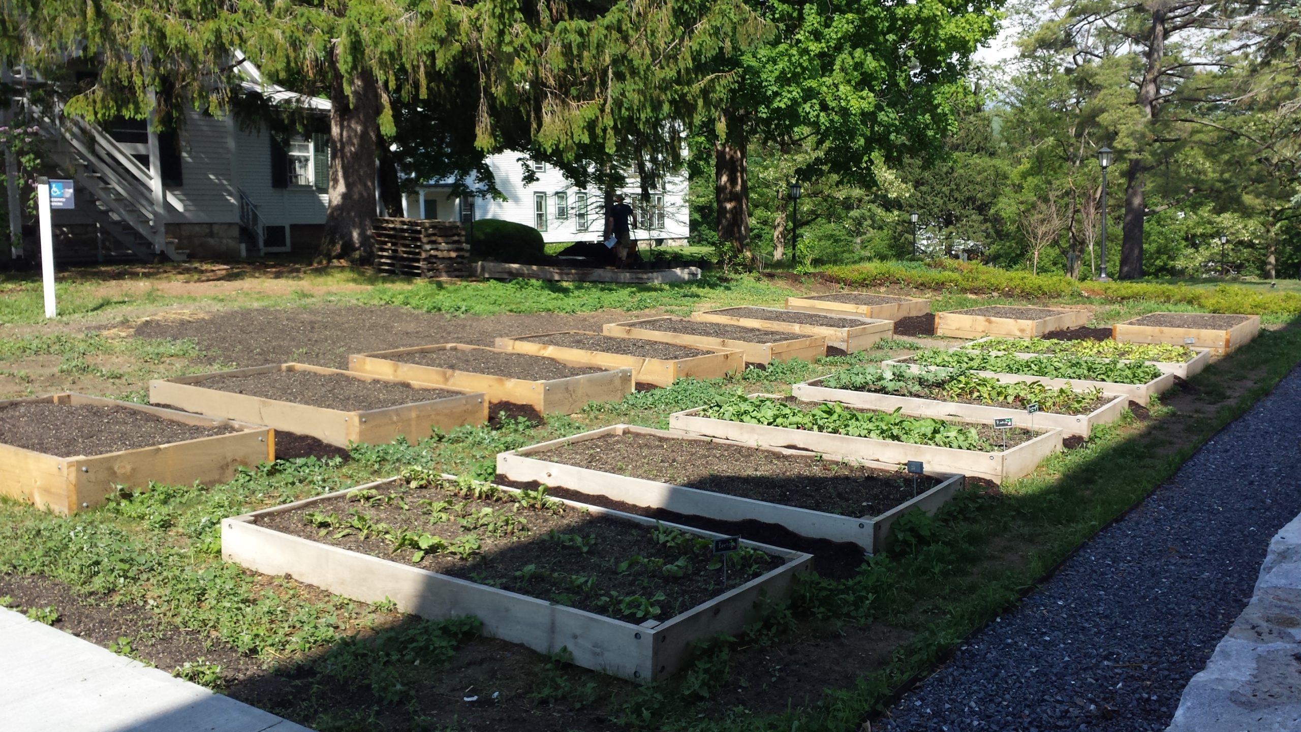
Pre-project photo of the Garden Beds (without signage) behind the 1966 Environmental Center
The garden beds are an integral part of the Envi Center. Under the Living Building Challenge certification, the building is required to operate as a net-zero energy and water space, with 35% of the surrounding land area in food production. The beds are supported by the Center for Environmental Studies (CES) and the Zilkha Center (ZC), and maintained by ZC interns and Williams Sustainable Growers (WSG). Additionally, Landscape Ecology Coordinator Felicity Purzycki advises overall orchard maintenance.
These gardens provide opportunities for community building, food production, and help teach students new skills. With these goals also come challenges. While talking to Christine about the signage project, she mentioned how garden interns already have a lot to do maintaining the gardens. This has made it difficult to find bandwidth to create signage about what is being grown and share meta information about the gardens. In addition, the current wood cookies used for signage are beginning to fade. For more than four years, the Zilkha Center has wanted a more permanent and prominent solution to identify and distinguish plants grown; this will also help ZC interns and other people to know what is ready—or not—to pick. The new signage will cover three areas: identifying the perennial and annual plants, teaching people how to use the gardens through the honorable harvest, and when certain items are ready to be picked.
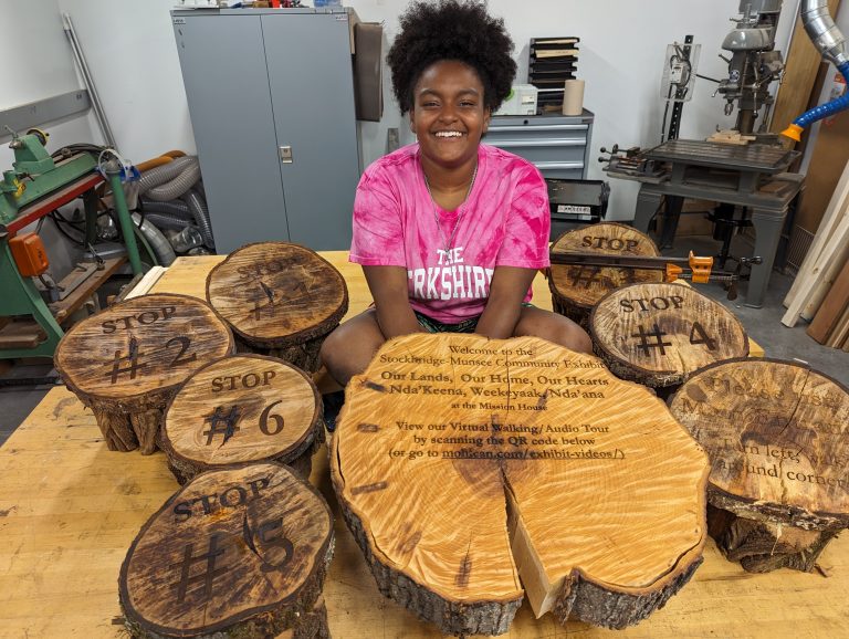
Yoheidy sits with her series of laser engraved wood slabs. She later added a laser engraved metal QR code label that directs users to the hosted video tour.
Inspiration was taken from a project recently completed by Yoheidy (Yoyo) Feliz ‘26, who engraved wood slabs to make signs for visitors going through the virtual exhibit tour at the Stockbridge-Munsee Tribe’s exhibit in Stockbridge. Those wood slabs were sourced from Hopkins Memorial Forest which is also where our project’s journey began!
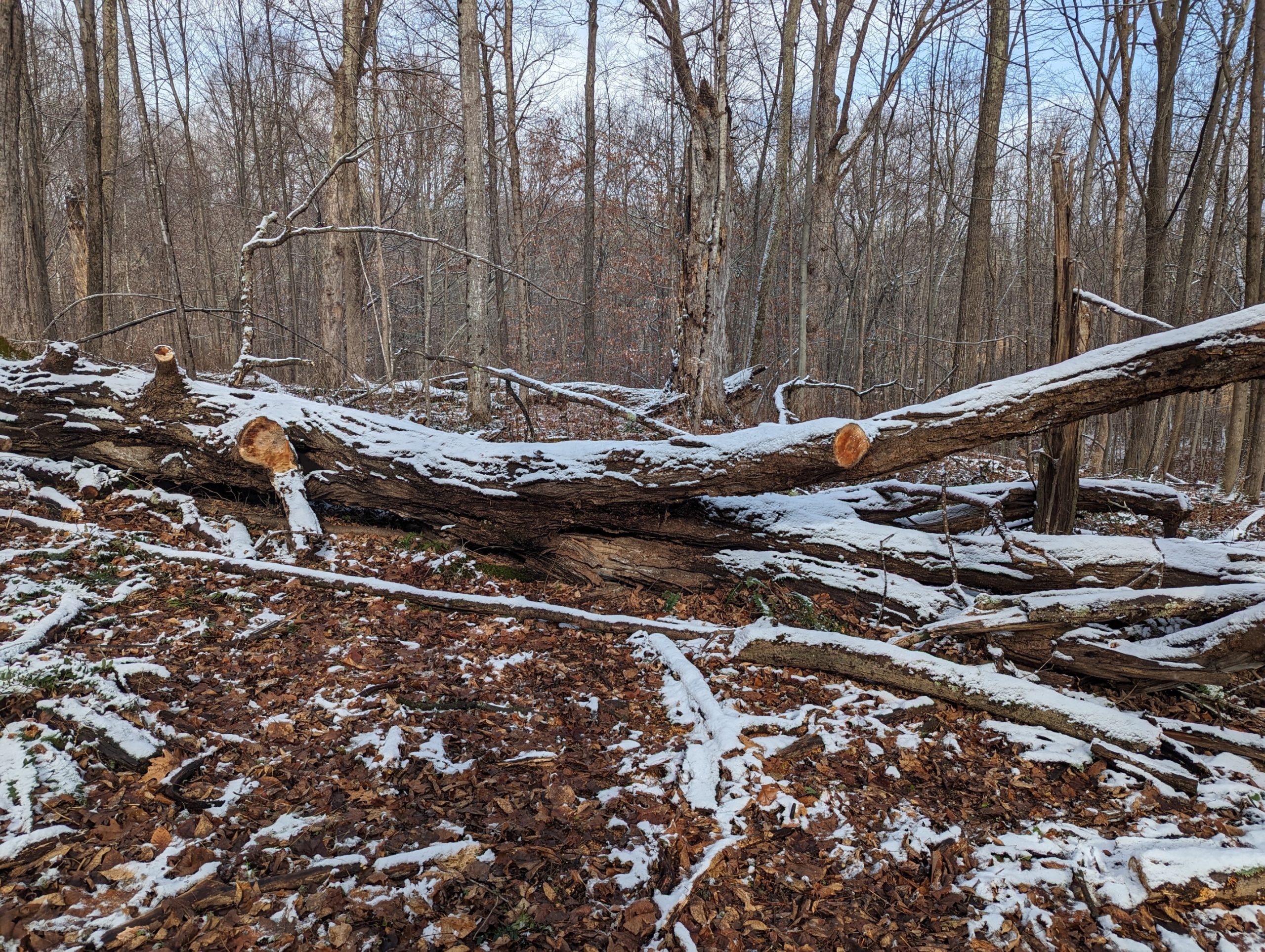
The sugar maple that provided logs for the signage
We received Sugar Maple logs claimed from the old grove across from the sugar shack with the support of Josh Sandler, Interim Hopkins Forest Manager. This tree fell two years ago, and had not yet been repurposed; the tree was part of the maple sugar grove that has a long history of being used for maple sugaring in Hopkins Memorial Forest. The logs were harvested with the help of a chainsaw by caretaker Javi Jenkins-Sorensen ‘25 who has a lot of experience in forestry.
Logs into Lumber
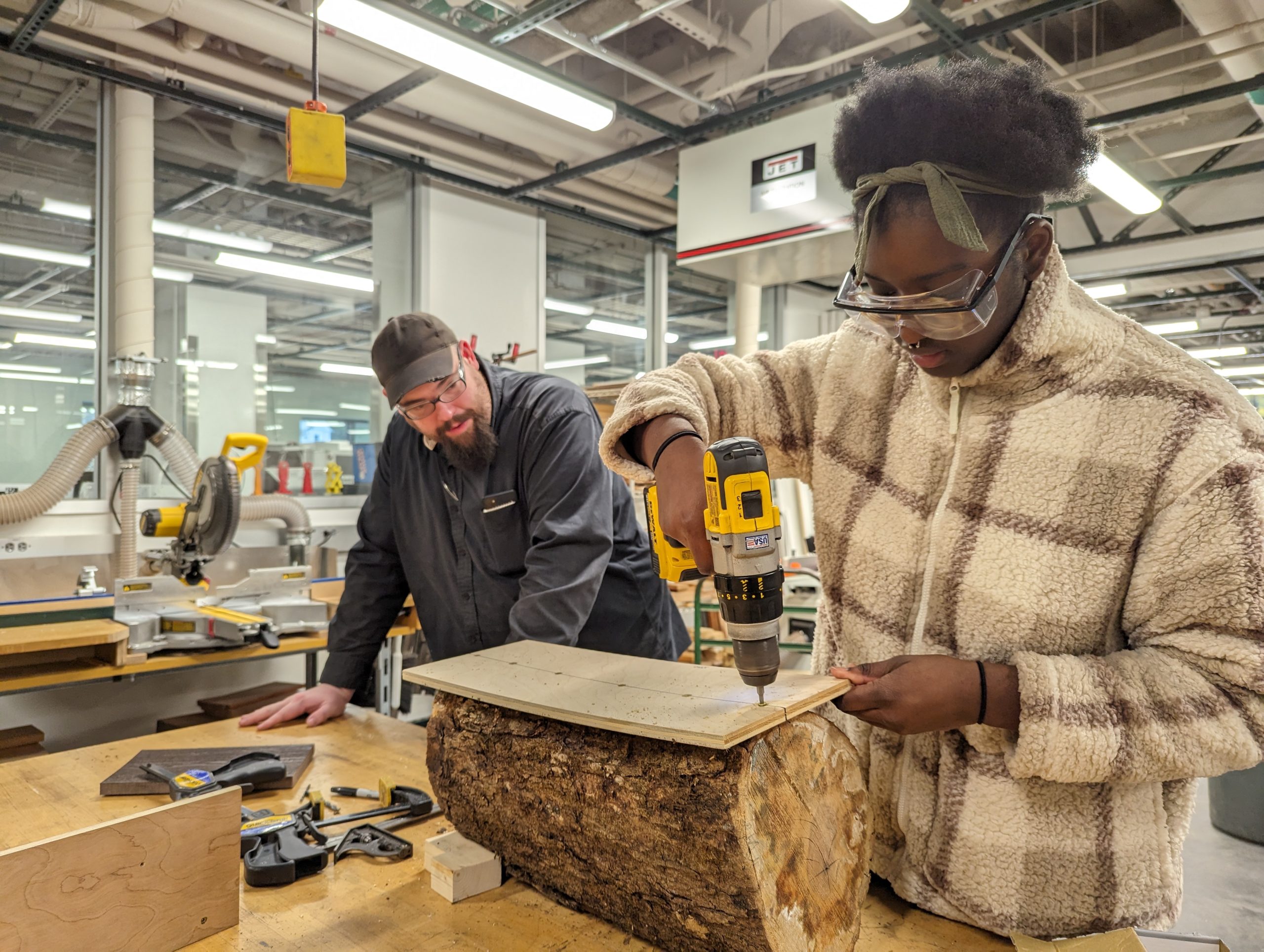
Sam Samuel ’26 creating a temporary sled guide to saw logs into planks with bandsaw
Once we received the logs, we had a series of sessions in the Williams Hopper Science Shop with Makerspace Program Manager David Keiser-Clark and Instrumentation Engineer Jason Mativi. Our goal was to mill the logs into 35 planks measuring 4″x20″ with approximately a 1″ thickness. We purchased cedar posts—that had formerly been telephone polls—locally from the Eagle Lumber sawmill in Stamford, VT. In the end, we were able to create exactly 37 planks, leaving us with precious little room for error.
Given the unevenness of the natural logs received, the first step was to build a sled (a platform) that would stabilize each log as we sliced them into planks with the bandsaw. We affixed each log to the sled with a couple screws (carefully avoiding the path of the bandsaw blade), sliced to create a flat side, then rotated the log 90 degrees and sliced again. After making two contiguous flat sides, we were able to slice the log more conveniently by using the bandsaw fence and tabletop.
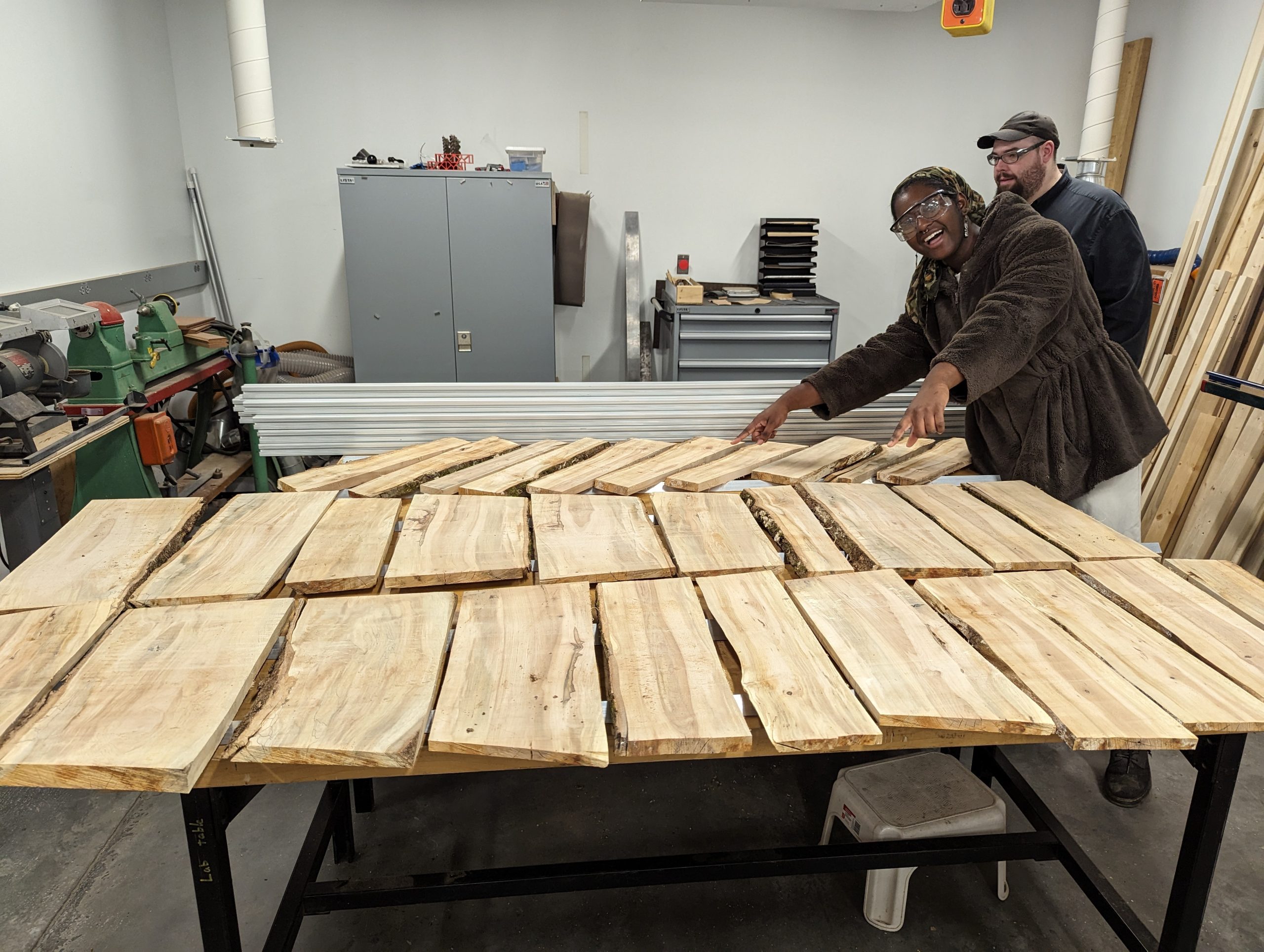
Completed lumber that was then left to dry for a week.
After cutting each plank, we let them dry for a week; this allowed them to shrink and to cup or curl (warp) a week. Before drying, the maple measured between 8 to 20% moisture content. Typically when letting wood dry, you want to stack your lumber with spacers to allow air flow to all sides, and allow it to dry for six months or more. Because we were short on time, we used spacers and placed weights on top of the stacks, hoping to aid them in drying flat. After a week of drying, we were able to visually see shrinkage and some warping.
We then used the wood jointer to create one flat edge; this process created a nearly perfectly flat and square edge that was perpendicular to the wider section of the board. We then placed that flat edge against the fence of the table saw to create a second clean edge parallel to the jointed edge. We used the jointer again to create a nearly perfectly flat surface on the wide side of the board. Next we used the thickness planer to flatten the top face of the plank and be parallel with the bottom face. This work resulted in creating beautiful rectangular sugar maple planks that were both parallel and square. We repeated this process for each board.
Engraving
After we had jointed, sliced, and planed the maple logs into boards, Mativi and David taught me how to use the Epilog Laser Helix engraver to make a Welcome sign, informational signs for the Rain Garden, Solar Meadow, and Picking Sign, and also 31 plant identification signs. It was my first time using a laser engraver and I had to be conscious about placement, size, as well as laser power and speed. Using CorelDraw (software), I centered each sign’s text to the middle of the engraver platform, which ended up being 12 inches on the x-axis and 9 inches on the y-axis. I worried endlessly about placement and sizing so I first experimented on matboard. Despite my experimentation, I still had some underlying issues given varying thickness and placements that are evident in my very first attempts at engraving. Each laser engraving requires 15 to 20 minutes, and I often repeated that process two or three times to burn a deeper image into the wood.
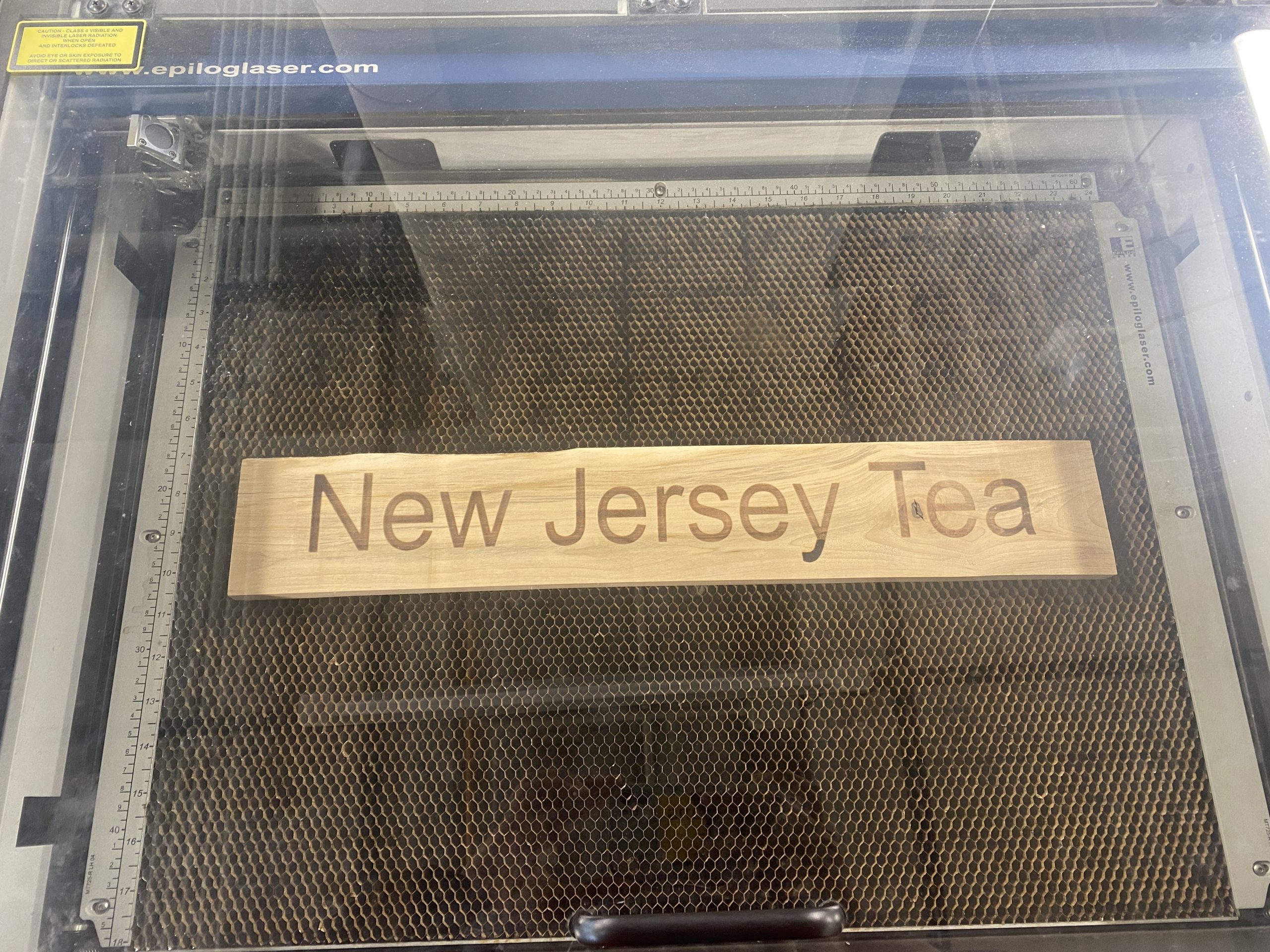
Plank inside of Epilog Laser Helix after one round of engraving
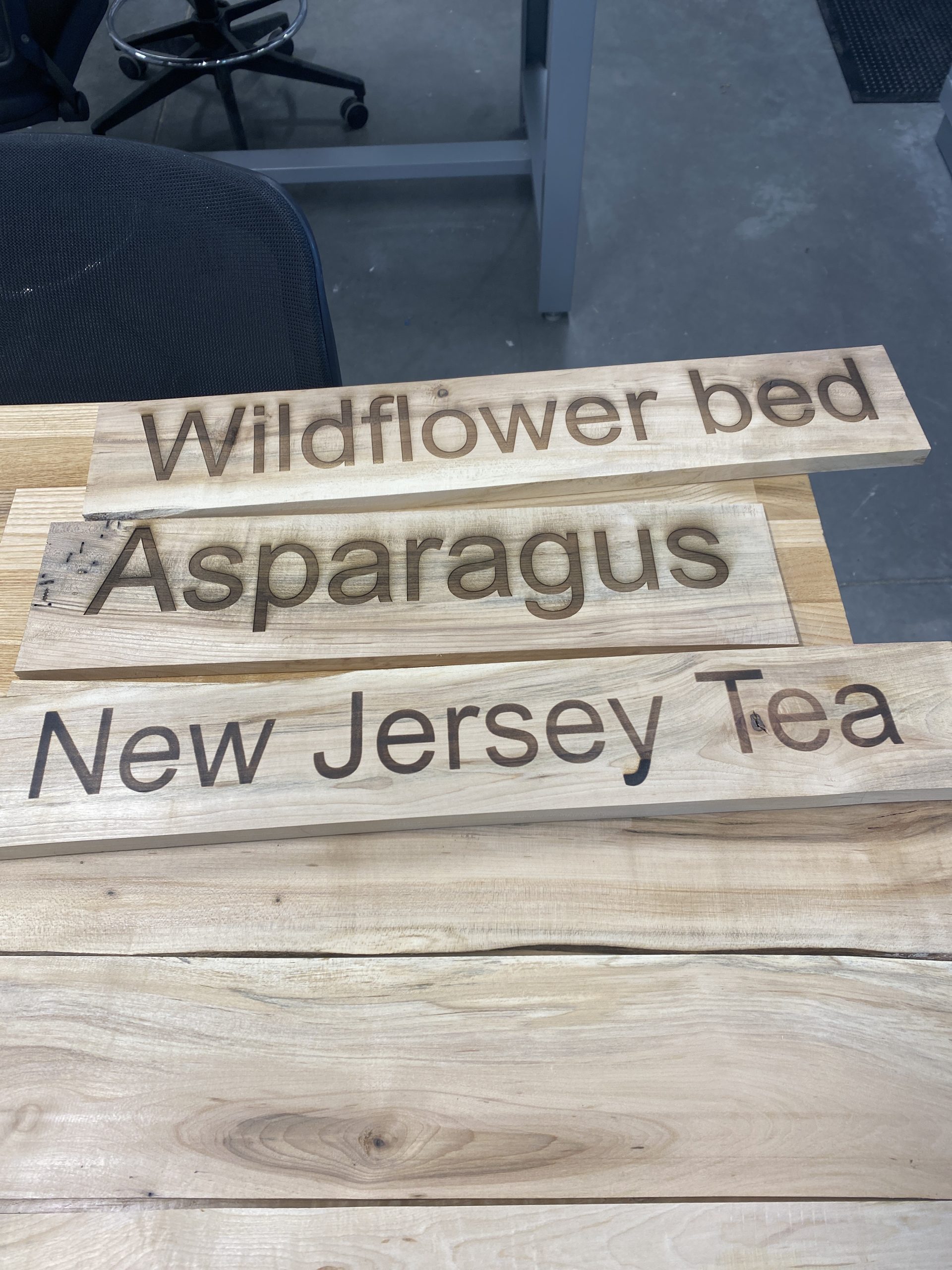
First batch of completed planks for plants
Next Steps
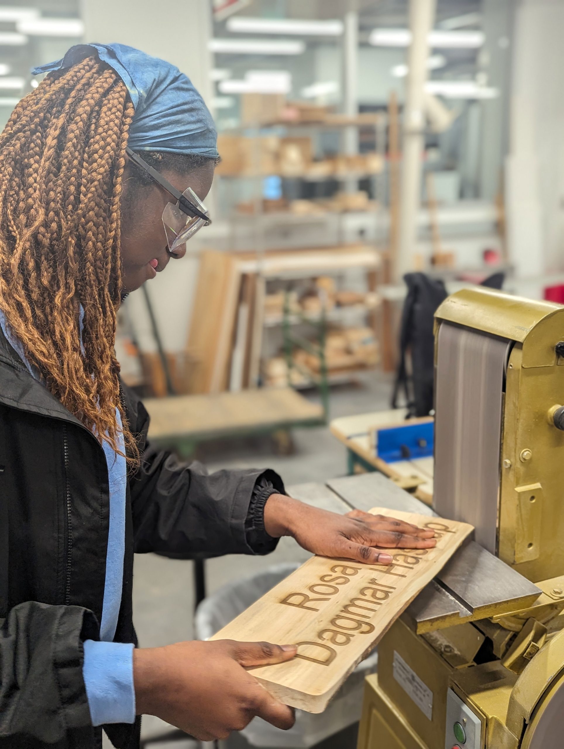
Sam Samuel ’26 rounding corners with belt sander
I expect to complete laser engraving all of the signs within the next two weeks. The next step will be to affix the signs onto cedar posts; Jason Mativi has already cut those into 48” lengths including a spiked tip to make it easier to drive them into the ground. The final steps will include sanding the sharp corners and adding a 100% natural Walrus tung oil preservative to better show the grain and improve longevity. Because our wood is dry, we will increase the ratio of tung oil and Citra solvent from the standard 1:1 to instead be a 2:1 ratio (2 parts tung oil, 1 part citra solv) and then warm that mixture and add in beeswax (4:1 ratio of tung/citra to beeswax) for additional protection. It will be exciting to see the signs all over the Envi Center gardens!
Postscript (May 2, 2024)
Sam Samuel ’26 with 37 laser-engraved signs made for the Envi Center community gardens.

Sam Samuel ’26 with 37 laser-engraved signs made for the Envi Center community gardens. This project used locally sourced sugar maple logs from an already fallen tree in the Hopkins Memorial Forest. Hopkins student caretaker, Javi Jenkins-Sorensen ‘25, used a chainsaw to cut the tree into logs. Sam then used a bandsaw, jointer, planer, various sanders, a laser engraver, and hand tools to create these magnificent signs.
Postscript (June 21, 2024)
We learned that weather removes the (pretty) charring that results from laser engraving.
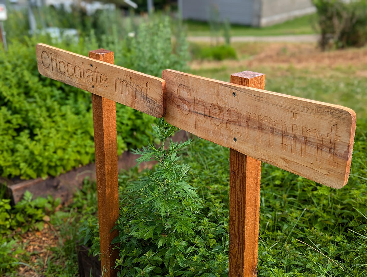
Laser-engraved signs installed in the Envi Center gardens
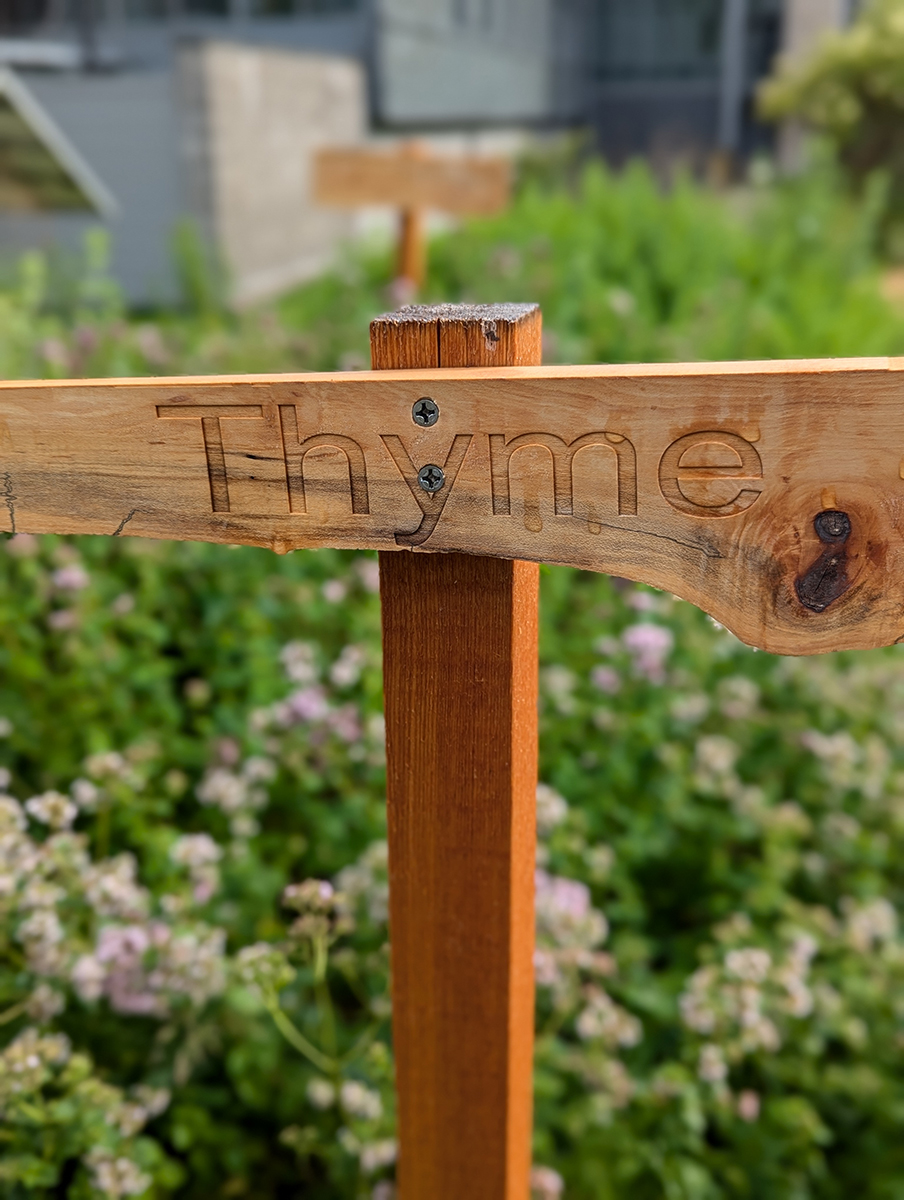
Laser-engraved signs installed in the Envi Center gardens
Postscript (April 25, 2025)
Much needed maintenance has been completed on the signs!

Newly painted signs: We learned that weather removes the (pretty) charring that results from laser engraving. Carefully painting the engraved letters restored the much needed contrast between the wood and the descriptive word(s).

Newly painted signs: We learned that weather removes the (pretty) charring that results from laser engraving. Carefully painting the engraved letters restored the much needed contrast between the wood and the descriptive word(s).

Irenee Niyibaho and Isabella Penna-Ward preparing to paint the laser engraved words in the signs