Imagine tinkering with a Generative AI. The orthodoxical scenario with Generative AI is that you ask it a question and it gives you an answer. But this time, rather than asking a question, you dictate how it answers the question. Instead of being a mere user, you are the brain behind the AI.
What is generative AI?
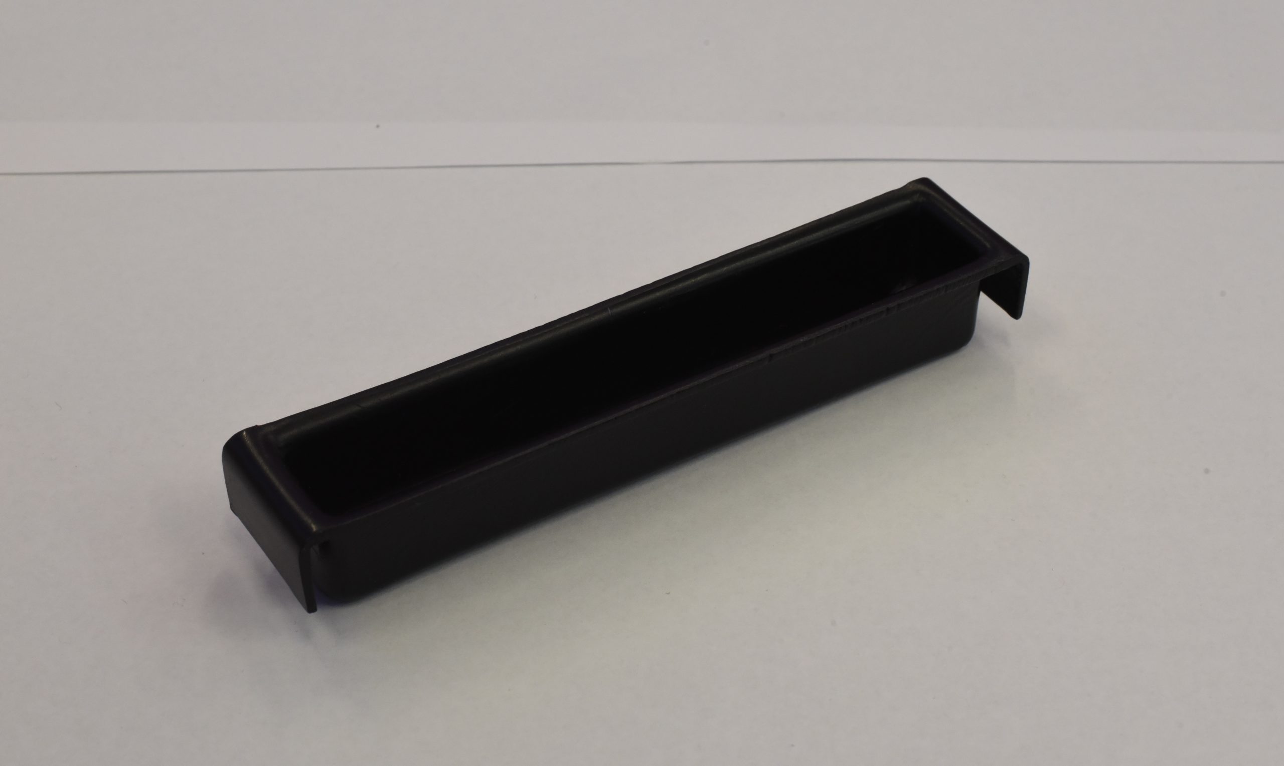
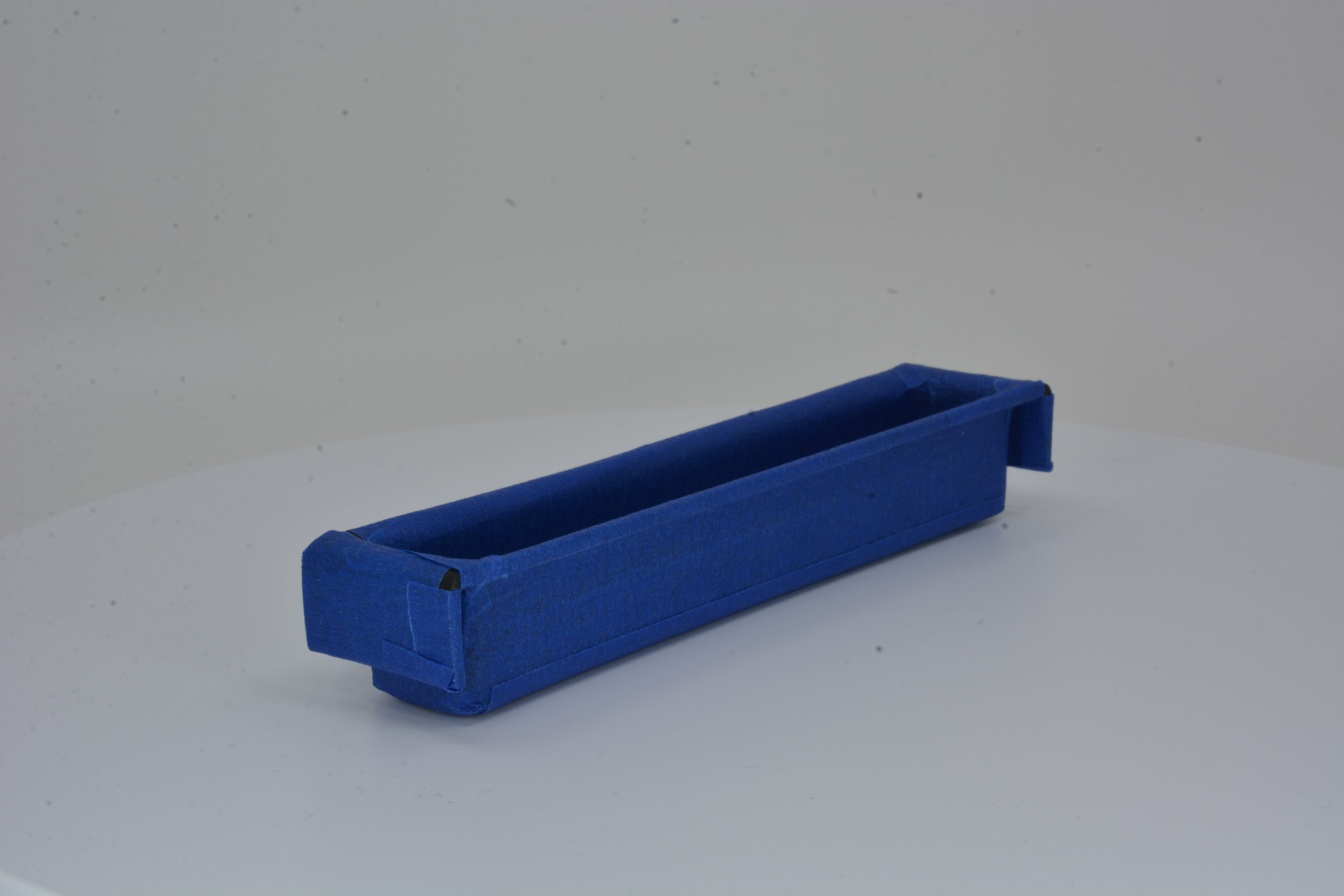
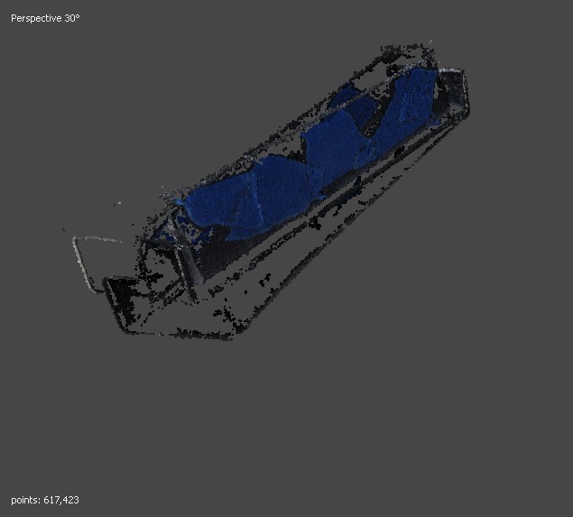
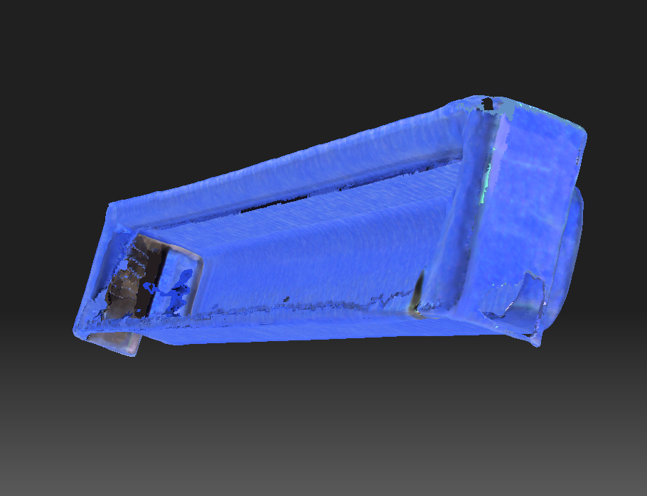
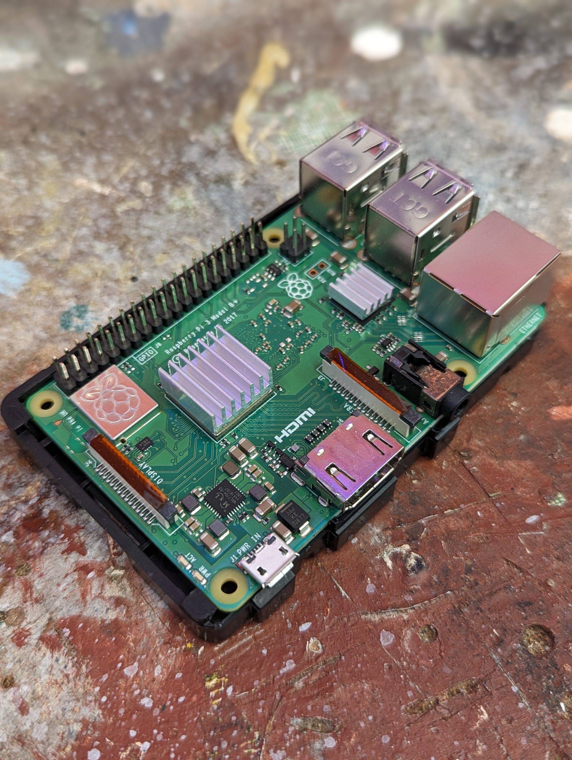
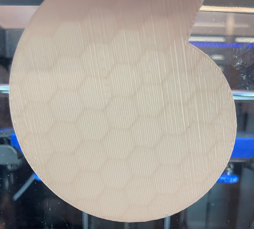
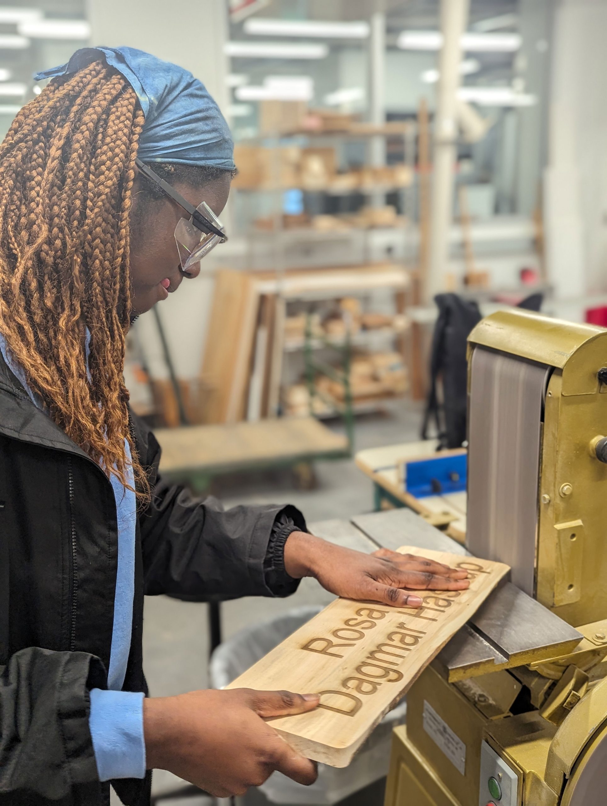
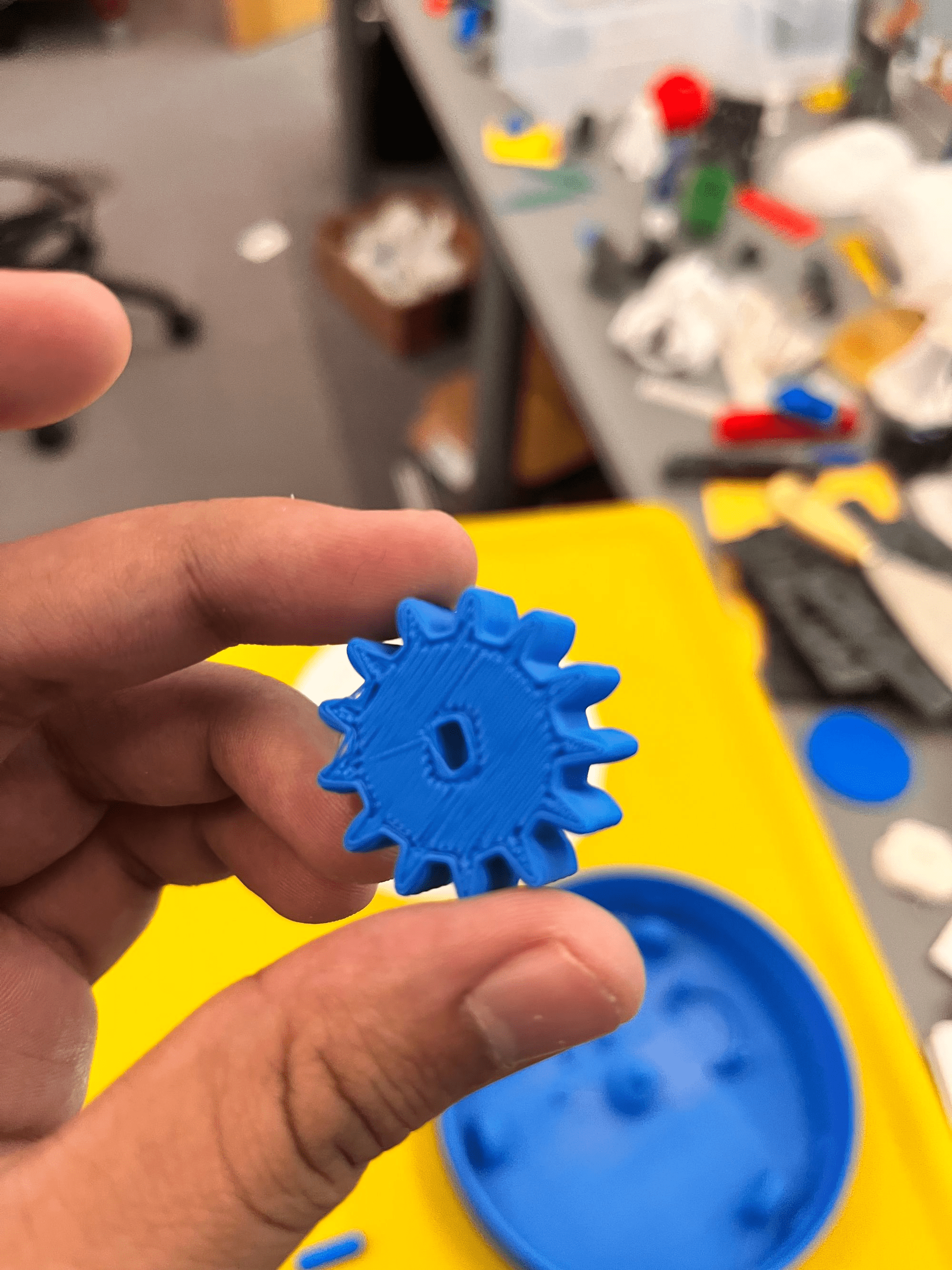
3D printed case (using high-temperature ASA filament)
A type of AI that quickly generates answers, information, and contents based on the user’s variety of input (Nvidia, 2024). It typically has an interface where users can type their inputs. Generally, these models can have text, images, sounds, animation, 3D models, or other types of data as inputs and outputs.
At Williams, there exists a local generative AI called EphBot. Unlike the mainstream generative AI (e.g. ChatGPT, Gemini) which connect you to a huge database stored in powerful servers, EphBot is a tiny device that can be held in a real person’s hand. The EphBot offers AI for experimentation and exploration while ensuring complete data privacy because it is local and does not interact with the Internet or other databases.
Now what?
The Office for Information Technology (OIT) at Williams College is developing another micro AI just like EphBot. Mr. Gerol Petruzella is an Academic Technology Consultant in OIT and the project developer of the upcoming micro AI called NanoBot. I asked him about the purpose and significance of the project and he responded with,
“For students and faculty at Williams to explore and experiment critically with generative AI. I believe passionately that all Williams students should have the opportunity to be more than merely users of generative AI applications.”
The NanoBot project is the 2nd anticipated microAI of Williams College. It is a generative AI like ChatGPT and Gemini. However, instead of being just a user, NanoBot gives you the opportunity to experiment on the AI itself.
Why is it necessary to create a casing for the microAI?
Before I go deeper into that question, let us scrutinize the story from the start. Gerol is+ using the NVIDIA Jetson Nano Developer Kit to create the NanoBot. It is a small AI computer that allows a user to build practical AI applications, cool AI robots, and more.
“I reached out to the Makerspace because the Jetson Nano Developer Kit provides a bare board, but no case or enclosure,” said Mr. Petruzella.
He noted that the Jetson Nano Developer Kit, which is the NanoBot itself, lacks a protective enclosure to its main body. This would be bad especially for hardware like this that is intended to be presented and used by a variety of people on loan through the Williams Library.
“Since my goal is to develop units which students and others in the Williams community can check out and use, the device needed a case, to make it sturdy and usable (avoiding both damage to the device and harm to the user!)”
Indeed, a protective cover would make the device itself sturdy and also avoid the risk of harming the people that are going to use it. But from what types of harm would the enclosure offer protection specifically?
Physical Protection
If the NanoBot will be used by the public, we cannot deny the fact that accidental bumps, drops, and other physical impacts that could lead to damage are likely to happen. Not to mention dust, dirt, and other particles that can accumulate on internal components and cause malfunctions.
Thermal Management
The enclosure is designed to have ventilation in order to help dissipate heat generated by the hardware, preventing overheating and ensuring optimal performance. By controlling the internal environment, it can help maintain a stable operating temperature for sensitive components.
Electrical Safety
It may be a small device, but it is still powered by electricity. The enclosure can provide electrical insulation, protecting users from accidental contact with live components and reducing the risk of electric shock. The enclosure would serve as the countermeasure and we know that it is better to have a countermeasure than to have a cure for electric related damages.
You can read more here about enclosures.
Why not just order one online?
“I couldn’t find any commercially-available case for this model, but I did discover a recipe on Thingiverse, so using the resources of the Williams Makerspace seemed like a great solution,” said Mr. Petruzella.
The main objective of this project was to fabricate a cost-effective enclosure for the Jetson Nano Board. Specifically, this project aimed to create an enclosure that can:
- Protect the device from physical impacts
- Withstand high thermal activities without melting
- Serve as an outer insulation for the device
Printing with ASA Filament
Filament Type: PolyLite ASA
Specification:
- Print Temperature: 240 – 260 °C
- Print Speed: 30 – 50 mm/s
- Bed Temperature: 75 – 95 °C
- Fan: OFF
Caution
The fumes emitted by the ASA filament can be potentially dangerous when inhaled. It emits a smelly & intense smoke that comes from Styrene present in this plastic compound (MakeShaper, 2020). This fume can cause health issues such as headaches, irritation, and so much more. It is recommended to use a fume extraction system while printing. We used BOFA fume extractors.
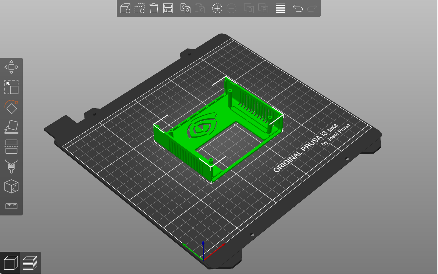
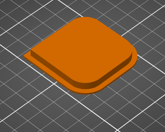
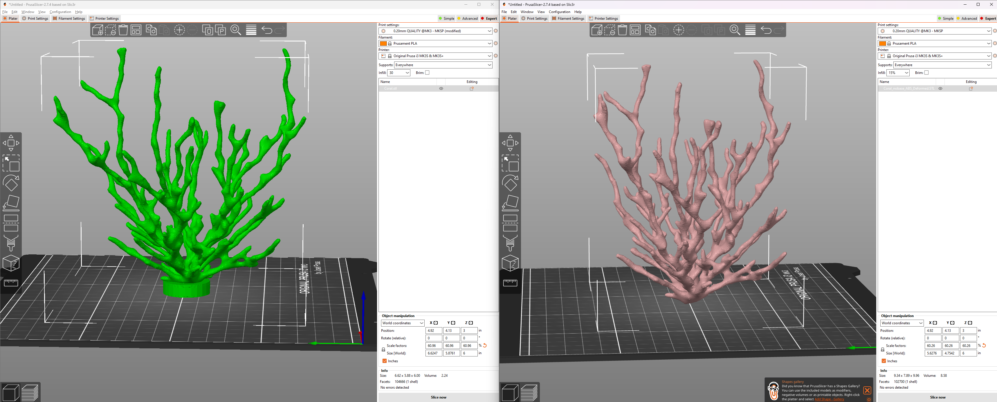
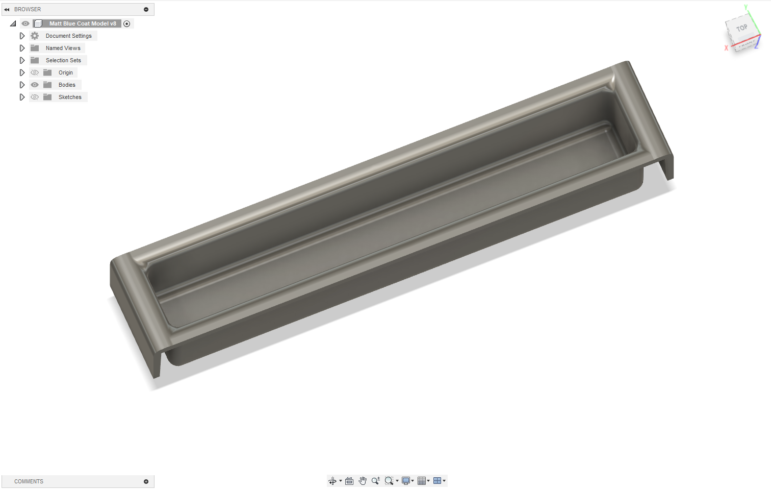
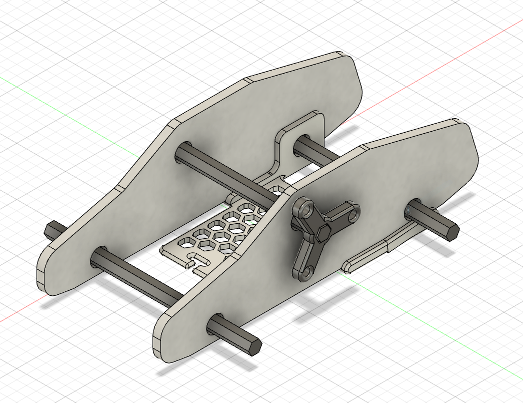
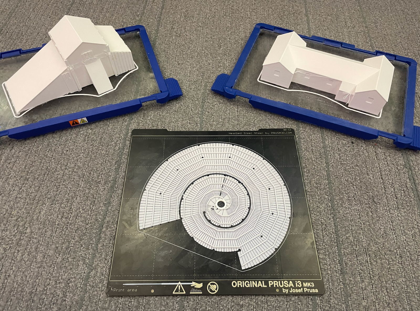
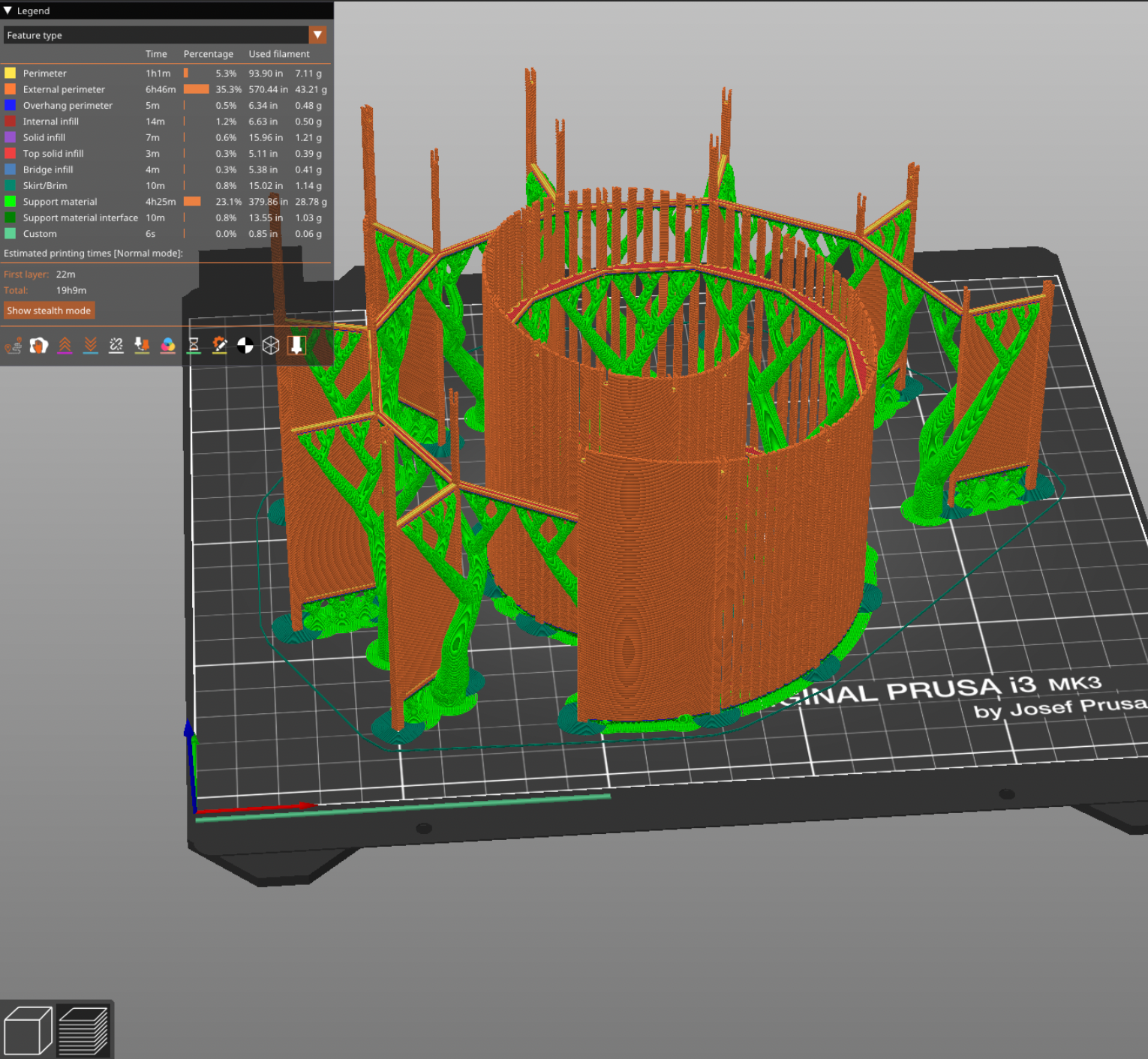
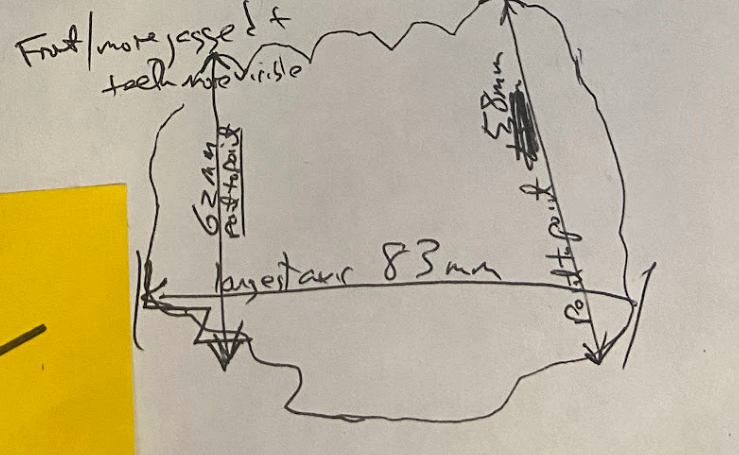
Blueprint of the top enclosure in Prusa Slicer Software.
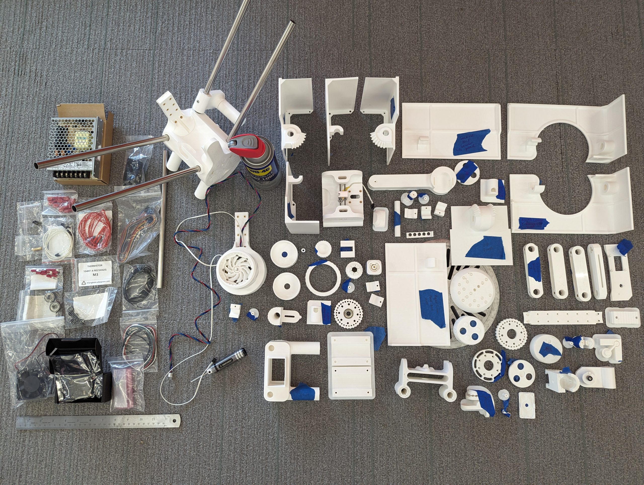
Step 1: Acquire the 3D Model of the Enclosure
The 3D model was pre-modeled by Ecoiras in thingiverse. I downloaded and converted it into a file that the Prusa i3 (3D Printer) can read using Prusa Slicer software. You are always welcome to customize your own design.

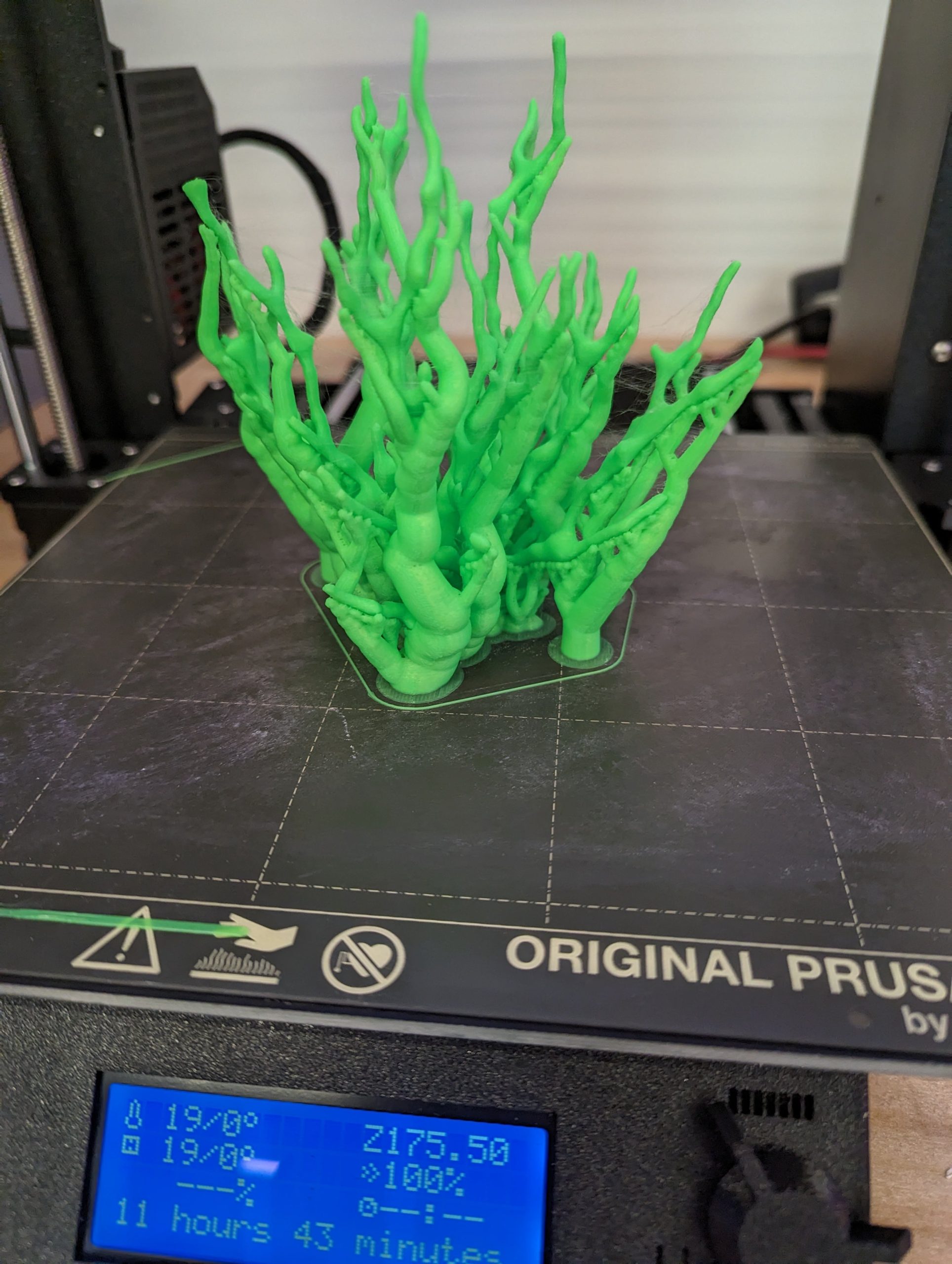
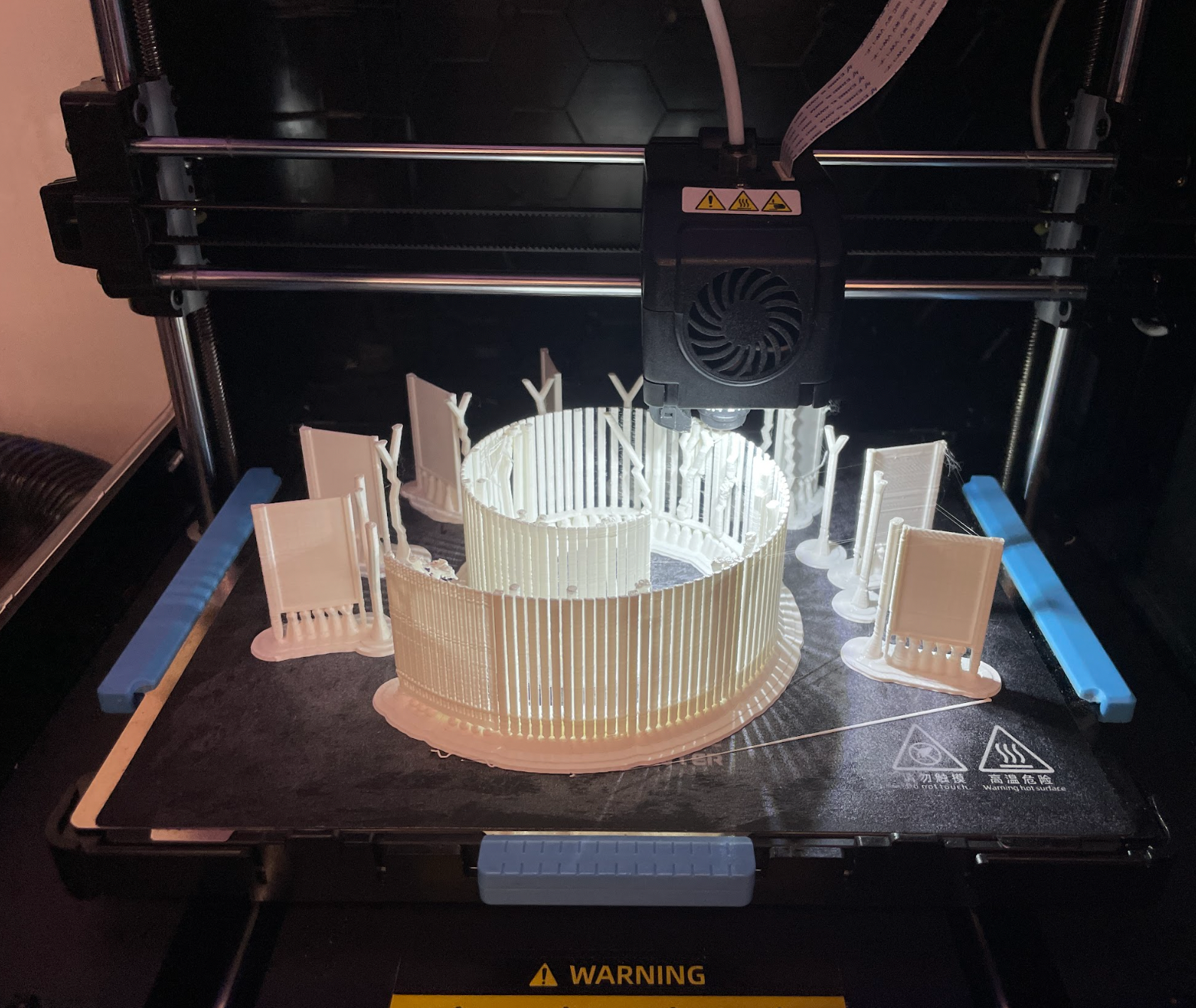
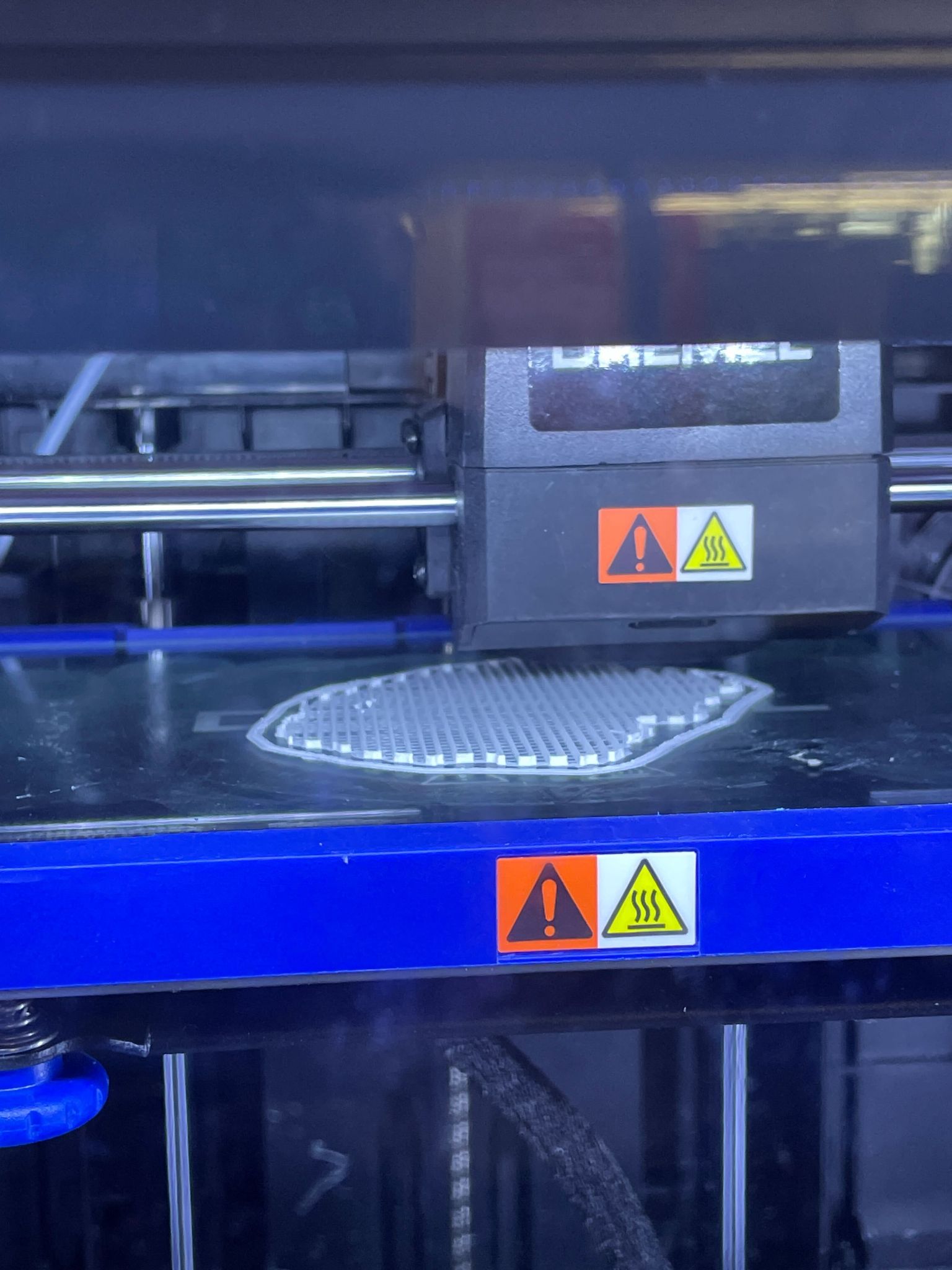
The Prusa i3 (3D Printer) printing the enclosure.
Step 2: Configure the 3D Printer and Load the Assigned Filament
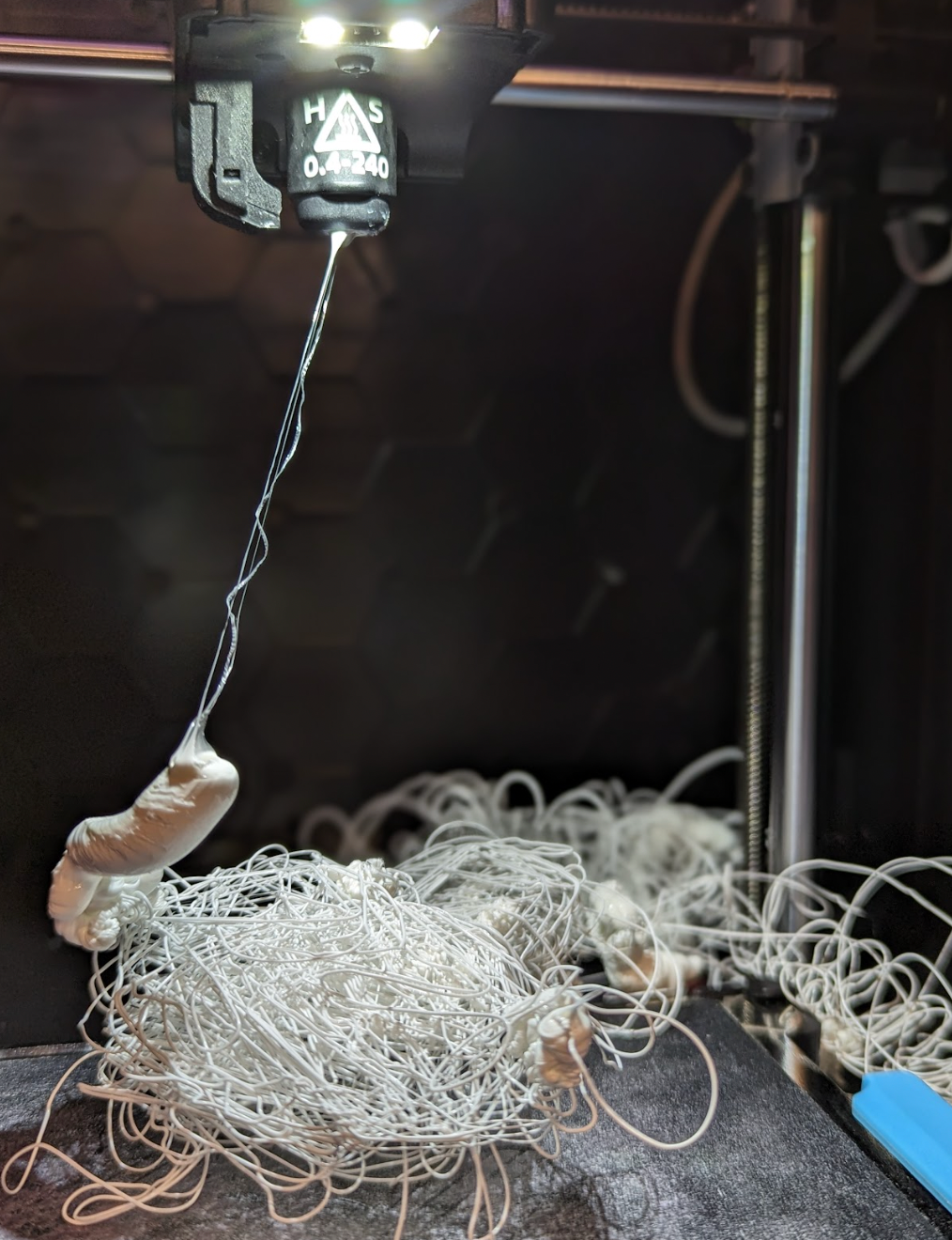
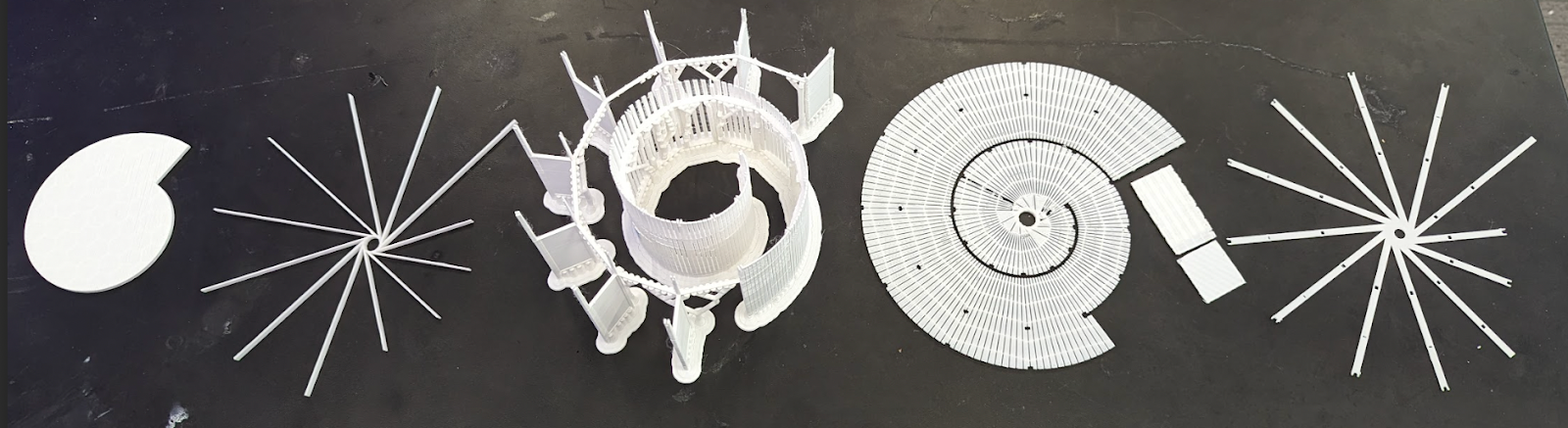
Then, wait for it to print. It may fail to print sometimes, but it is totally normal for it to fail. Print and print until it succeeds. After it successfully prints the product, slowly scrape it off from the plate from which it was printed.

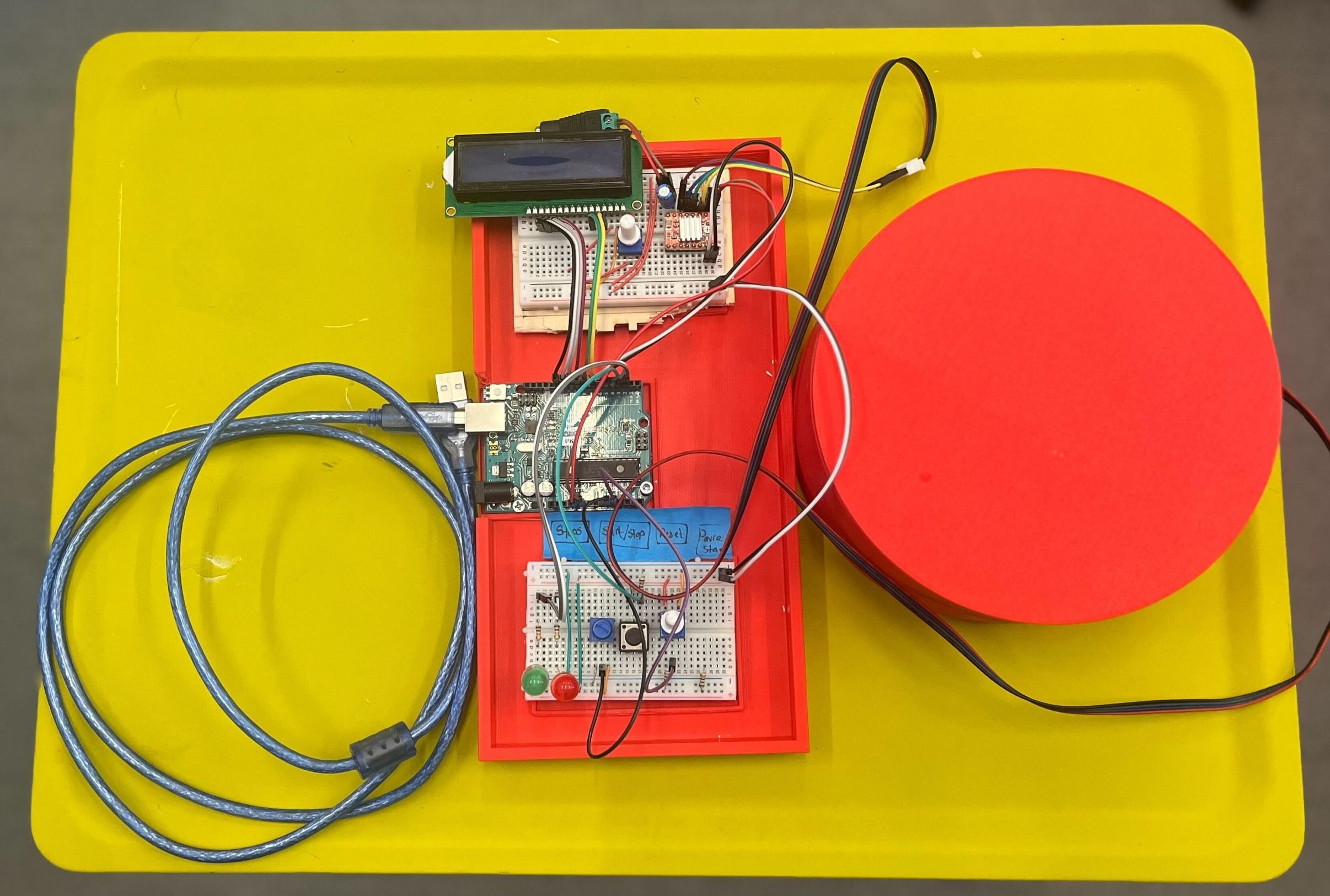
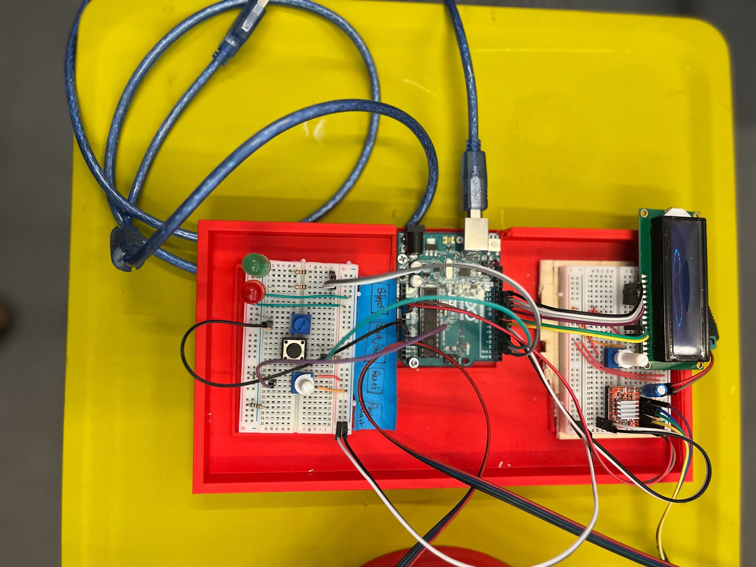
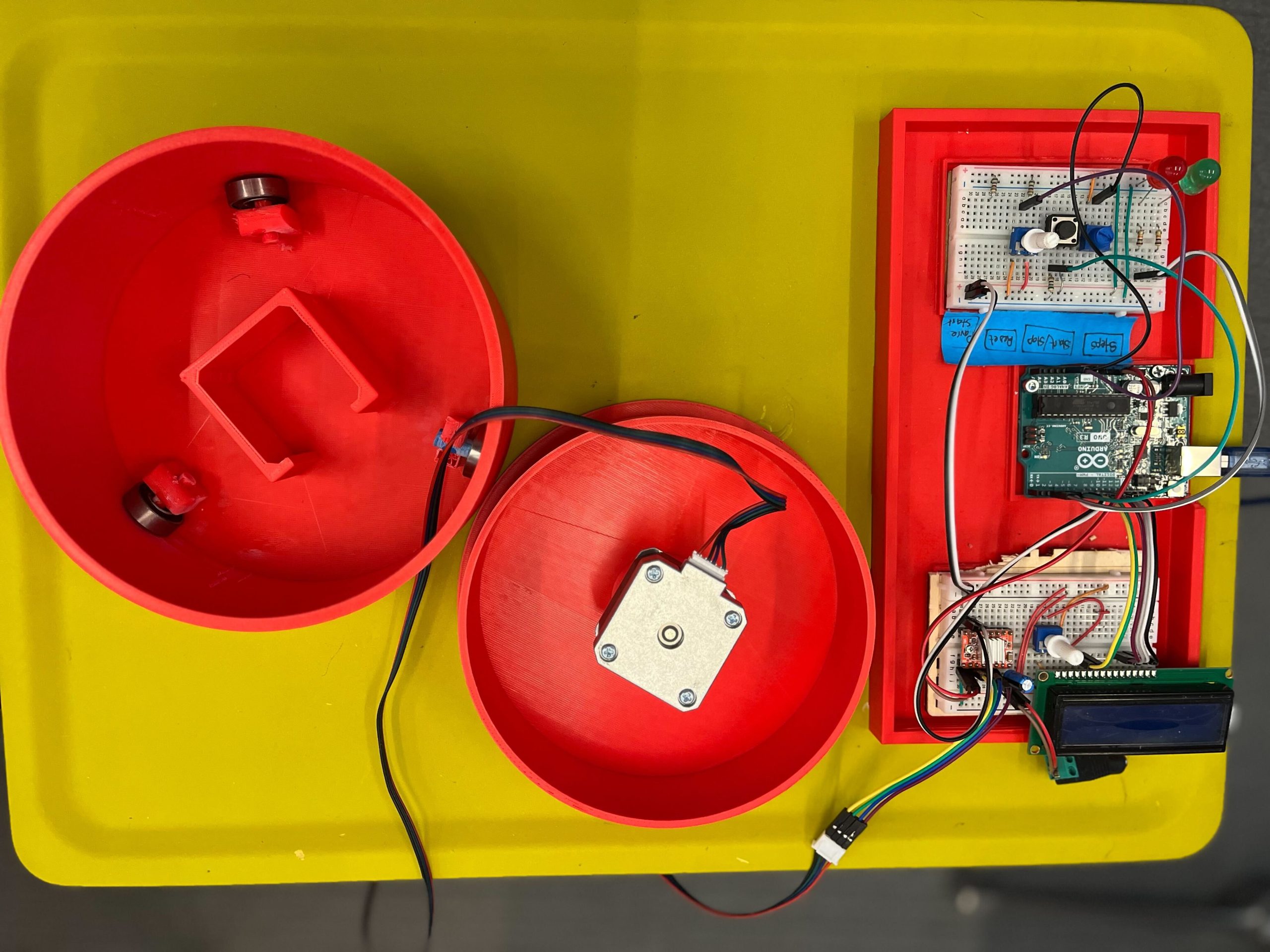
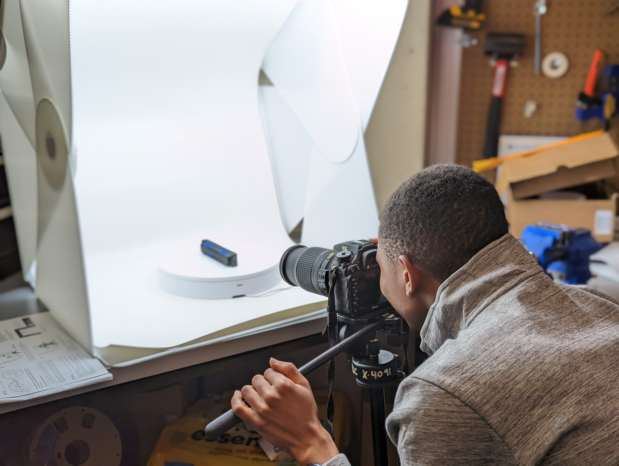
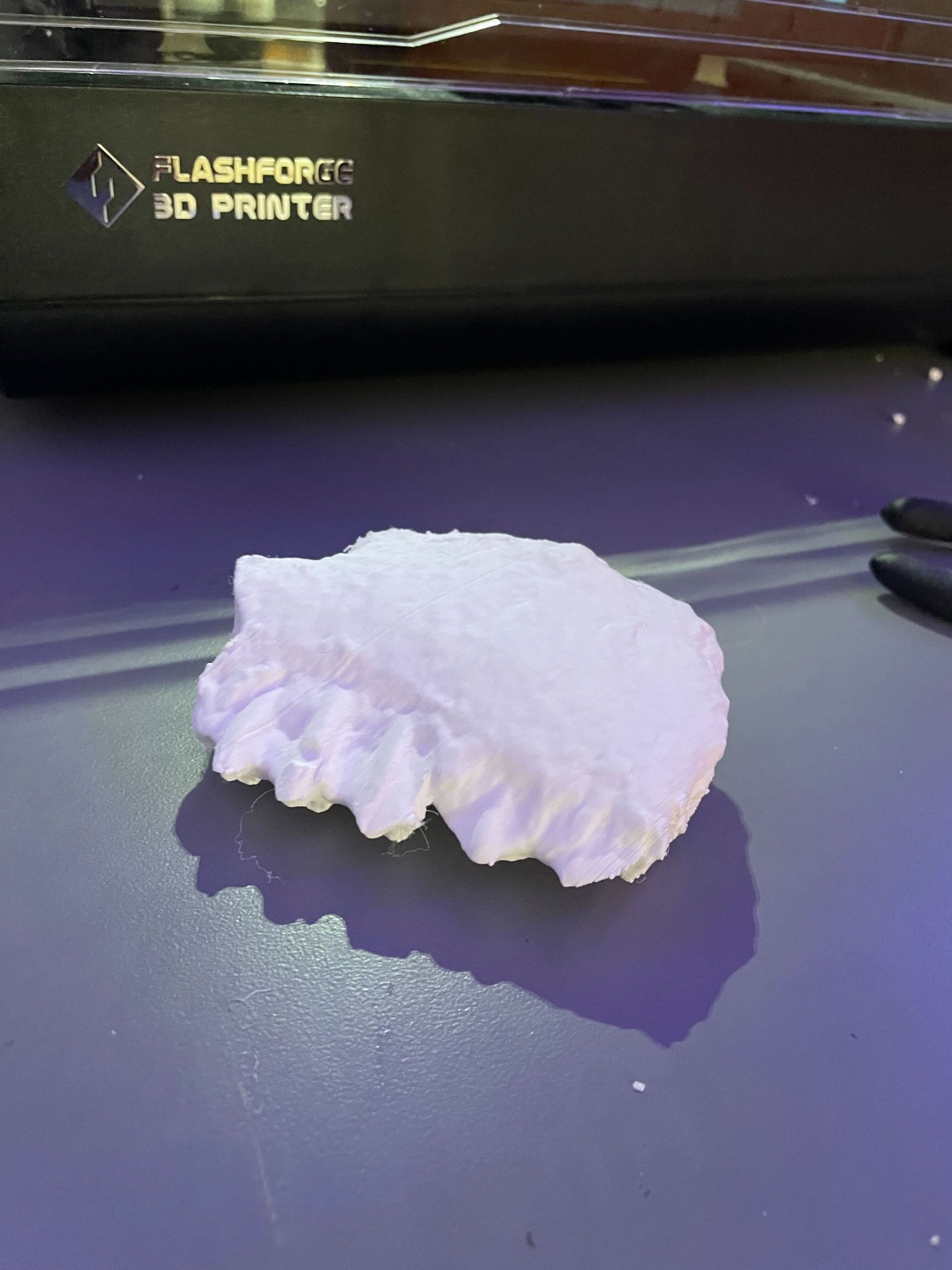
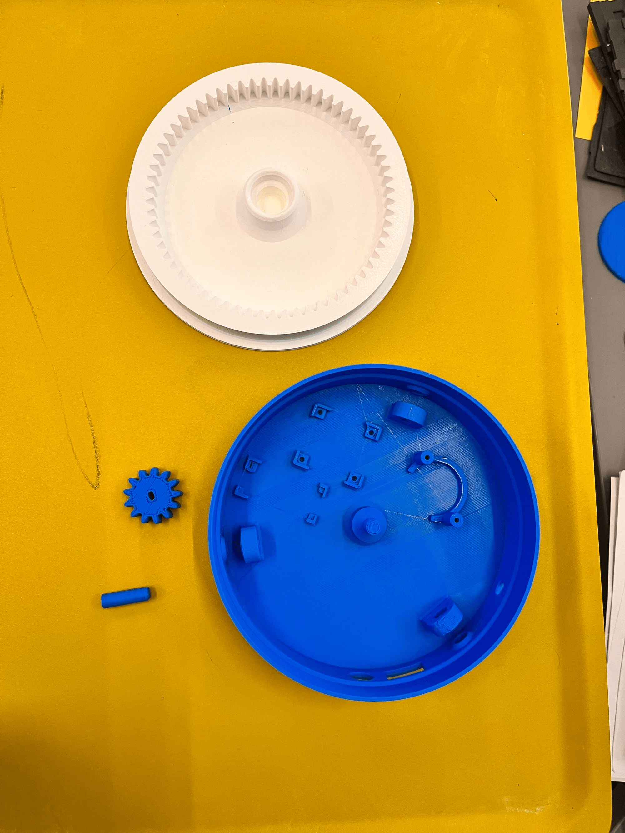
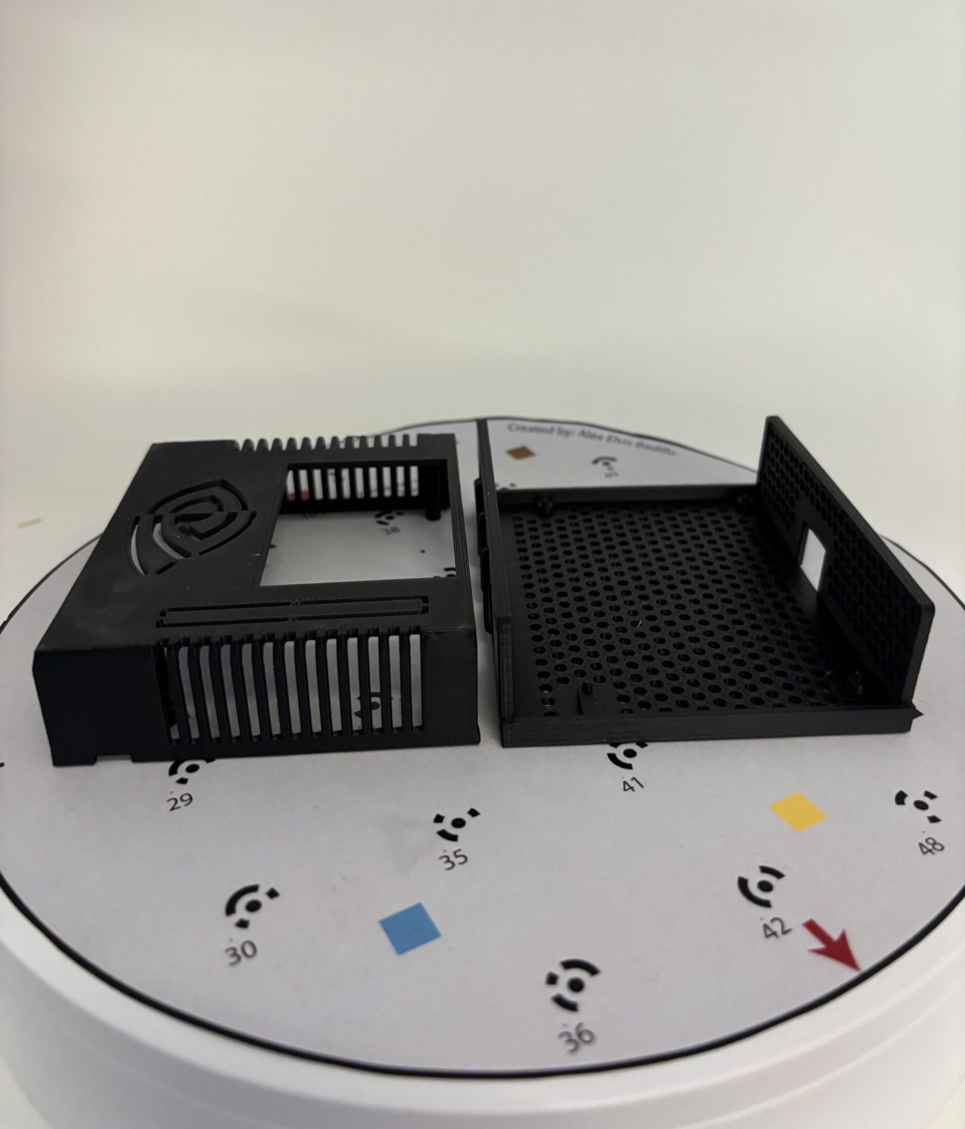
The NanoBot with its new enclosure.
Step 3: Fit the Finished Product.
This is the finished product. Feel free to change the color if you want. We chose to print this case in ASA filament, instead of the more common PLA filament, because ASA offers a melting temperature that is higher by about 50 degrees Celsius. That means that the heat generated by generative AI computing is less likely to melt the case.
Community
In this technology-driven time, the generative AI’s performance and popularity continuously rise. It is inevitable as we proceed in times where advancing technology is prominent. NanoBot will empower students and faculty to become active participants rather than passive consumers of generative AI technology.
The NanoBot gives users the ability to transcend the state of being mere users—how do you want to configure AI?
Resources
Nvidia. “What Is Generative AI?” NVIDIA, 2024, https://www.nvidia.com/en-us/glossary/generative-ai/
MakeShaper (2020). 3D Printing: Understanding more about ASA filament applications. Makeshaper. https://www.makeshaper.com/post/3d-printing-understanding-more-about-asa-filament-applications