Alumni Reunion Weekend at the Makerspace

During the sunny and pleasant reunion weekend of June 7th and 8th, the Makerspace was bustling, offering tours and hands-on making experiences to over 200 Williams alums and their families. We prepared a hands-on project that would allow people to use 3D-printed molds to cast Makerspace-themed coasters, sourced from upcycled Amazon cardboard boxes. This fun experience allowed us to share and discuss an environmentally friendly DIY project that people could easily replicate at home. People can even create their own custom molds!

During the alumni reunion weekend, the kids seemed most excited to mix the ingredients, mold the pulp, and finally clamp the coasters. They also got to take home coasters that we had prepared (and dried!) ahead of time.

Alums in the Makerspace on June 7th, 2024

Alums in the Makerspace on June 7th, 2024

Recipe

  • Cardboard boxes (50g)
  • Water (170g)
  • PVA Glue (15g) (we used Titebond II woodworkers glue; Elmer’s white glue works, too)

Tools

Instructions

  • Cut the Amazon boxes into small pieces
  • Add into the blender: 50g of cardboard, 170g of water, and 15g of glue

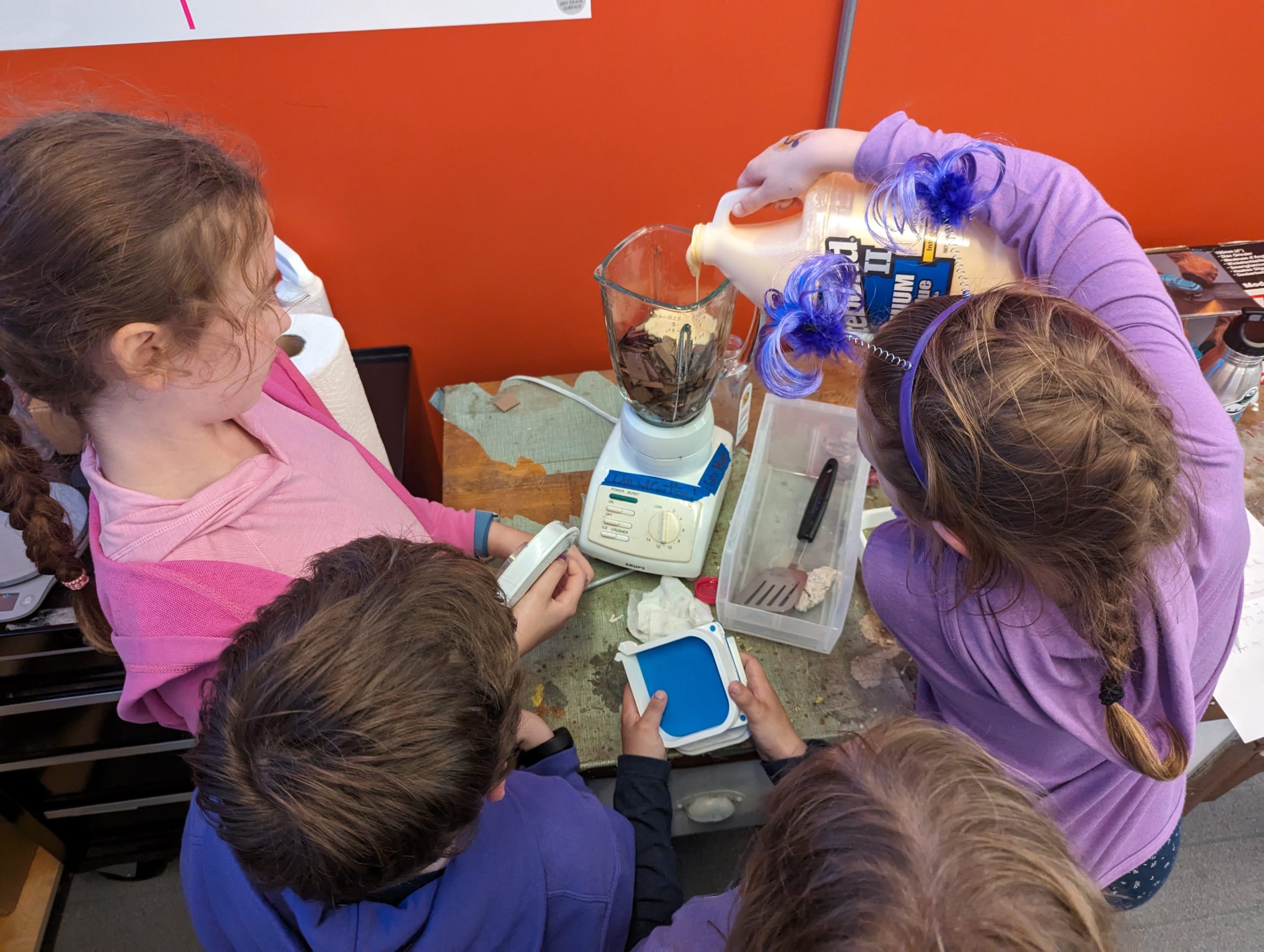
    The kids were excited to mix the ingredients (cardboard, water, and glue)

    The kids were excited to mix the ingredients (cardboard, water, and glue)

  • Blend until it’s thick and looks like wet clay
  • Assemble the 3D-printed mold: we used and modified this Pulp-it model

    Kids took turns squeezing extra water from the pulp

    Kids took turns squeezing extra water from the pulp

  • Put the pulp in a cheese cloth and squeeze the excess water out
  • Fill the mold with the damp pulp
  • Press the pulp with your hands so that it is dense and evenly distributed in the mold

    And this is how you squeeze the clamps on the mold!

    And this is how you squeeze the clamps on the mold!

  • Attach the lid to the mold
  • Press the mold using a clamp
  • Let it dry for 24 hours
  • Carefully remove it from the mold and gently place it to dry in direct sunlight (or in front of a fan or heater vent) for about 6 hours
  • It should now be 100% dry and solid
  • Nice work!
Fusion 360 software: We ended up iterating and tried inverting the extrusion of our design. Which version do you like better?

Fusion 360 software: We ended up iterating and tried inverting the extrusion of our design. Which version do you like better?

The kids had a blast making the coasters while learning about how upcycling minimizes waste in our environment. This activity demonstrated how individual action, no matter how small, may collectively impact positive change.

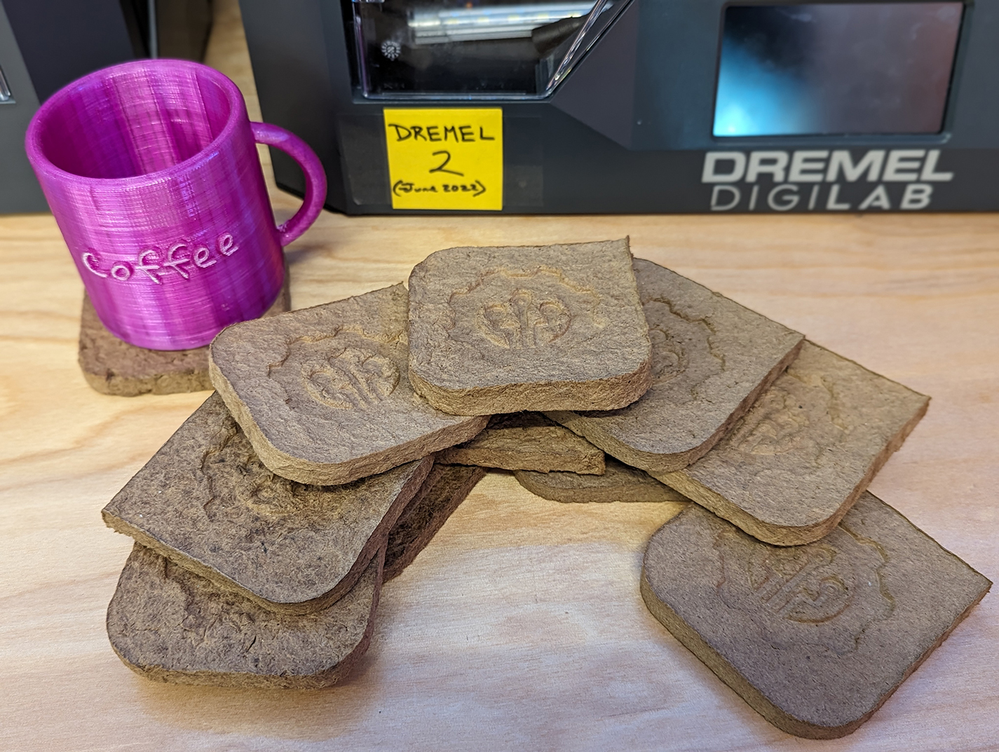
A pile of upcycled coasters made by our alumni's children (from scrap Amazon boxes)

A pile of upcycled coasters made by our alumni’s children (from scrap Amazon boxes)

According to the Environmental Protection Agency

Packaging materials account for 28.1 percent of the total municipal solid waste (MSW), amounting to 82.2 million tons of generation in 2018. This amount poses a high environmental risk and requires systemic and individual actions to mitigate the risks.

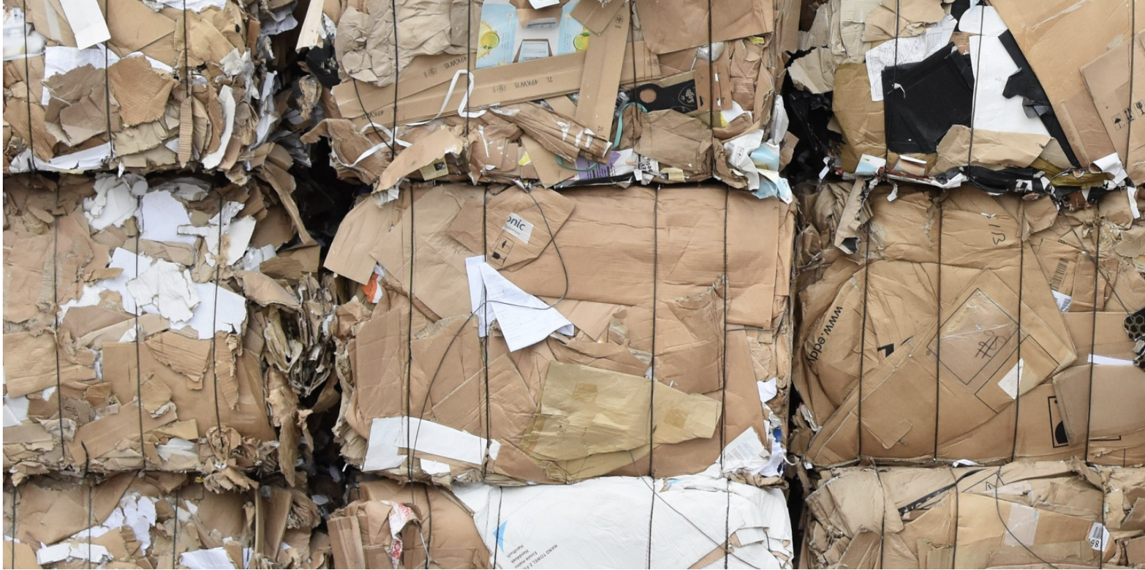
A pile of Amazon boxes

A pile of Amazon boxes

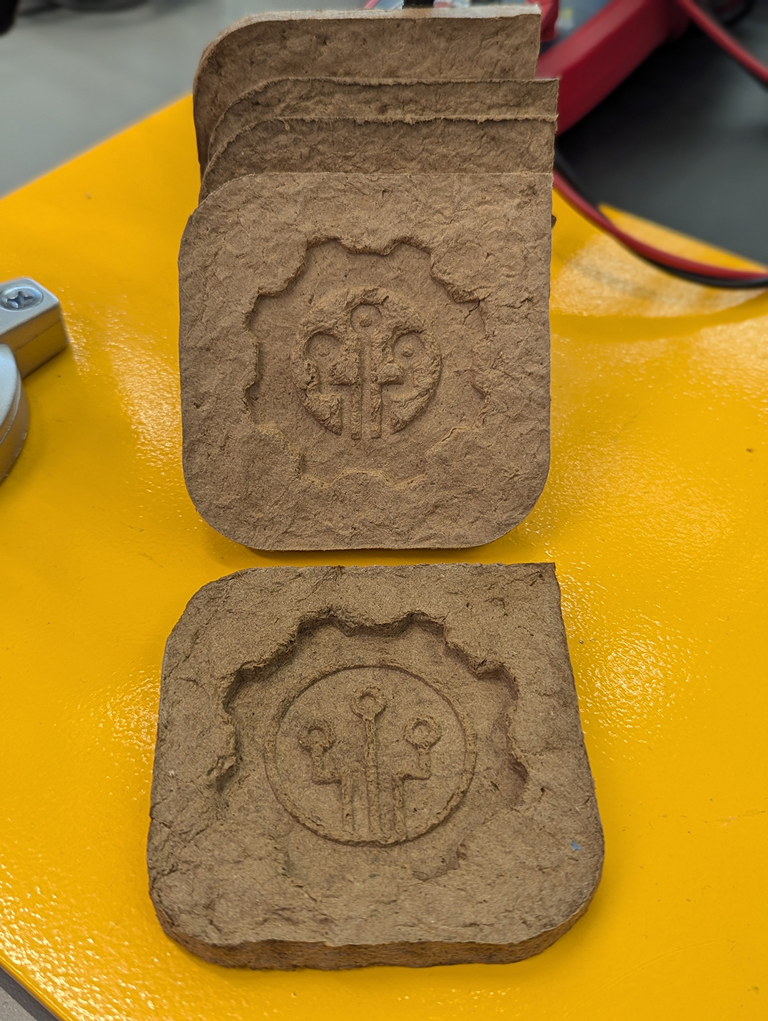
We were inspired by this Pulp-it project, and then we modified their open-source parts by using Fusion 360 software to add the Makerspace logo onto the coaster. To do this, we added an image of the logo and then extruded (raised) it about 8mm. To minimize waste, we tested our prototype models by printing it at 15% of the actual size. 

Fusion 360 software: Before adding our logo

Fusion 360 software: Before adding our logo

Fusion 360 software: After adding our logo

Fusion 360 software: After adding our logo


TIDE Grant: Sustainable and Reusable STEM Learning Kits for Students in Under-Resourced 5th and 6th Grade Classrooms

Written by Divine Uwimana ’27 and Elena Sore ’27

Introduction
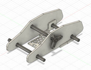
Our latest prototype of the car includes a winding mechanism, which will act as an additional modification of the base kit.

Our latest prototype of the car includes a winding mechanism, which will act as an additional modification of the base kit.

In an ideal world, students would have equal access to education, but that isn’t the case. While some schools have the latest learning technologies, hands-on opportunities, and all the funding they need, others are trying to give students the highest quality education they can without access to these resources. Worst of all, the schools negatively impacted are often in historically underrepresented communities, often ones with large populations of people of color, perpetuating a cycle of poverty. While brainstorming ways of helping our local communities as part of the TIDE Grant (Towards Inclusion, Diversity, and Equity Grant) proposal, providing more equitable access to STEM education was a clear way we thought we could make an impact. Building these STEM kits is a way we Williams students can use our education and access to help build up the community around us.

What is Hands-On STEM Education?

Hands-on STEM education uses physical interaction to provide real-world experiences that help reinforce the concepts being taught. While they can be helpful to the learning process, these experiences are often expensive. Whether it’s premade kits that can cost upwards of 40 dollars a student or involve costly field trips, these experiences often don’t fit within the budgets of schools. This disparity is critical to solve because studies have shown that hands-on learning opportunities help students retain what they learn better than standard learning methods such as lecturing. The problem is exacerbated in the education of younger students (K-6 range) because younger children’s lower attention spans can cause them to lose focus more quickly in the absence of active and experiential pedagogy.

This problem doesn’t only exist in a classroom setting. Many attempts have been made to bring hands-on learning to the home as supplemental education and homeschooling tools; however, cost is even more of a problem here. One of the largest companies currently producing these kits for home use is Crunch Labs. While they are similarly priced, averaging around $30 a kit, the requirement to purchase a monthly subscription typically results in costs of $300 or more per child. Also, Crunch Labs and other kits built for a home environment are often not reusable.

Access to hands-on STEM education is so important because high-quality STEM education improves students’ creativity and problem-solving skills. Research has shown that exposing kids to STEM in elementary school – especially between the first and third grades – provides students with the foundation they need to succeed in STEM-field careers. According to the research, U.S. adults with 1-2 years of experience in the workforce have reported the highest exposure to STEM concepts in elementary school. Between the ages of 5 and 8, 46% of this population experienced a STEM-related track in school and 53% of this population currently works in a job that is either entirely or heavily involves STEM – by far the largest percentage of any sector of jobs in the workforce. This suggests that exposing students to STEM at a young age captures their imagination and keeps them interested in science, technology, engineering, and math jobs early in their careers.

As student workers in the Makerspace, Divine Uwimana ‘27 and I, Elena Sore ‘27, met and collaborated with Paula Consolini, Adam Falk Director of the Center for Learning in Action, Tanja Srebotnjak (Director of the Zilkha Center for Environmental Initiatives), and David Keiser-Clark (Makerspace Program Manager). We identified a few critical criteria for STEM kits:

  1. Our STEM Kits need to be as low-cost as possible to produce. To ensure this, we must find creative ways to reduce material usage and implement supplies students may already have in their classrooms into the kits.
  2. We must design STEM kits to leverage existing lesson plans and learning requirements to ensure that the STEM kits fulfill the educational needs and standards set out by organizations like the Department of Education. 
  3. The STEM Kits must be designed to be reusable, durable, and sustainable, using sustainably sourced and produced materials wherever possible.

Brainstorming

Divine and I began the brainstorming process by researching existing STEM kits currently available on the market and how we might further improve them for our demographic group with respect to the aforementioned criteria. Since we both had little experience in the field beforehand, we wanted to understand better the design features other organizations used to create highly engaging STEM kits. Some of the qualities we observed that we believe we should replicate are listed below:

  • A good STEM kit is highly interactive. Parts of the kit, especially mechanical parts, should be designed so that students can visually see what is happening and how the action they are putting in is causing the final result.
  • A good STEM kit should not be a “one and done.” Ideally, a STEM kit will have multiple stages that allow students to build upon a product in stages, introducing new concepts or building on previous concepts.
  • A good STEM kit should be a manageable length. Even if students are having fun, dragging it out too long risks boring the students and causing the learning aspect to be ineffective.
  • A good STEM kit should be fun yet educational. This means balancing the kit to both be rich in academic concepts and interesting to keep them engaged.
  • A good STEM kit should encourage teamwork and cooperation. It should allow kids to work together to build their social skills while learning.
  • A good STEM kit should allow “trial and error.” It should enable the kids to learn from mistakes and thus build their problem-solving skills.
  • A good STEM kit should be simple yet visually complex. Just because the final mechanism is a complex contraption doesn’t mean the process of assembling it can’t be simplified and streamlined.
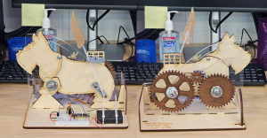
Front and back views of the mechanical scotty dog kit from Carnegie Mellon University.

Front and back views of the mechanical scotty dog kit from Carnegie Mellon University.

During our design process, we also got to experience assembling a STEM kit first-hand, specifically the mechanical Scotty dog kit we received from Carnegie Mellon University, courtesy of Professor Bill Nace and Professor Robert Zacharias. The materials used to assemble it are easy to manufacture, primarily made of thin sheets of wood and acrylic with 3D-printed plastic parts. The design is simple but very interesting; a single motor in the middle drives both the tail wagging on the back and the head bobbing on the front through a system of gears on the back. The head is made to bob up and down in a specific pattern through the radius of the spinning piece increasing or decreasing as it turns, creating a pattern of head movements that feels random. The tail spins on an arm and is locked upright using a bracket, making the tail wag back and forth with a simple spinning motion. Finally, all of this is controlled with a light sensor, allowing the user to control the speed of the motion by raising or lowering their hand above it. All these mechanisms combined to create a fascinating kit from a design standpoint, with a lot of interactivity and interesting mechanisms on display while being very quick for us to reassemble, even without instructions.

From this experience, we better understood how to design an effective STEM kit. Then, we started brainstorming ideas for STEM kits that we could create. At the end of this brainstorming, we ended up with three designs we wanted to develop further. The first is a model car, which would use a wind-up mechanism built by students to showcase the properties of potential and kinetic energy. The second idea is an energy kit expansion for the car, allowing students to electrify it while teaching them the basics of electricity and explaining renewable solar energy concepts. Finally, the third idea is a solar system kit, which would be focused on having students assemble a solar system model to teach about the planets in our galaxy and our place in the universe. With these initial ideas, we started prototyping the model car kit.

Prototyping the Model Car Kit
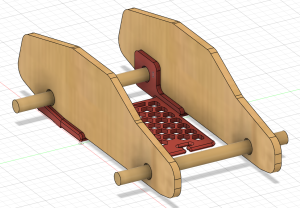
An initial prototype for the base car kit, giving us an idea of what the final product may look like.

An initial prototype for the base car kit, giving us an idea of what the final product may look like.

The main idea of our wind-up car kit was simple. But, as with many projects, it quickly evolved into a complex design with many digital iterations and three 3D printed prototypes. For this first design, a 3D printed base would connect the two cardboard sides and help support the back axle, which would wind up using a rubber band attached to it and the frame. Wooden dowels would act as axles and bottle caps as wheels, so when you pulled it back, the car would launch forward using energy stored in the rubber band. 

While this was a great initial idea, we encountered some problems. First, cutting out the sides made of cardboard proved difficult because two holes needed to be cut in the middle of it for axles. Ultimately, we decided that the side pieces should be replaced with laser-cut wood in the final design, which would be reusable and easier for kids to work with while providing more structural rigidity. Another issue we discovered was that the rubber band would stay on the axle instead of coming unhooked at the end, catching it, and abruptly stopping the car. Our solution was to move the hook point for the rubber band forward so it had enough energy to detach itself from the axle at the end. We also had to ensure this expansion didn’t use too much plastic, as we hope to create all the filament ourselves using recycled PET from locally gathered plastic bottles. We ended up using a honeycomb pattern, often seen in structures that use empty space to save material resources while retaining structural integrity, and by implementing this we were able to save sufficient plastic such that the larger prototypes consumed less plastic than our smaller initial prototype.
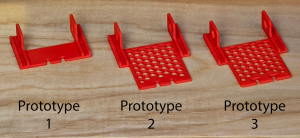
Our first three prototypes for the 3D printed base, showing how it evolved to meet the project's needs while remaining efficient in plastic usage.

Our first three prototypes for the 3D printed base, showing how it evolved to meet the project’s needs while remaining efficient in plastic usage.

For our third prototype, we rounded and smoothed as many parts as possible to prevent sharp points or edges that can occur in 3D printing. We also did this to prevent sharp points from catching or breaking the rubber band. Finally, we modified the slot at the front for the rubber band to help the car retain it, even after it detaches from the axle.

The biggest problem we ran into was not with the design of the base but with the kit itself. Our initial idea was interesting but violated one of our initial design rules. The kit was just one thing: assembling the car with the rubber band. If we wanted to make an exciting kit, we had to make at least one additional stage involving more engineering and differently demonstrating the concepts of potential and kinetic energy. 

While looking for inspiration, we stumbled upon a design by a maker named Greg Zumwalt for a 3D Printable Wind-Up Car that used a simple mechanism to limit the speed, allowing it to move farther and longer after windup as opposed to a design like ours, which simply went at top speed after release. Looking into this project’s mechanics, we realized that a similar design could be perfect to demonstrate the ways energy can be modified in the process of converting from potential to kinetic energy. So, to better understand how the mechanics worked, we downloaded the files and began printing them out to design a similar mechanism within the constraints of our model kit.

It was at this moment that the Office of Institutional Diversity, Equity, and Inclusion announced that our application for a TIDE grant was accepted and that our STEM kit project would be funded. 

Next Steps

Our next steps are to complete the second expanded energy source for our car prototype, align that with curricular concepts, and then meet later this month with an elementary school teacher to share our project and hear initial feedback. We plan to incorporate that feedback into the car prototype and then next meet with that teacher’s class and observe student reactions to utilizing it. As we continue to build several STEM kits, our theme will be to test, demonstrate, observe, seek feedback, iterate, and repeat. We hope these kits might have a significant impact on elementary students’ education in the Berkshires.
Whittle by Whittle: Envi Center Garden Signs 

When I was a prospective student, I recall my host bringing me near the Class of 1966 Environmental Center (“Envi Center”) to meet some of their friends. While passing through, I noticed a group of students picking apples from a tree and pulling weeds in the garden beds. As I took an apple from their bin and had a bite, I was incredibly overjoyed to see a garden after just having started one at my high school. Now, as a student and summer intern, I had the opportunity to see the hard work that goes into the maintenance to make the gardens a community space for all. This is why, when Christine Seibert, the Sustainability Coordinator at the Zilkha Center, reached out to the Makerspace for a project to make signage for the Envi Center gardens, I jumped at the opportunity to support this project!

Garden Beds behind the 1966 Environmental Center

Pre-project photo of the Garden Beds (without signage) behind the 1966 Environmental Center

The garden beds are an integral part of the Envi Center. Under the Living Building Challenge certification, the building is required to operate as a net-zero energy and water space, with 35% of the surrounding land area in food production. The beds are supported by the Center for Environmental Studies (CES) and the Zilkha Center (ZC), and maintained by ZC interns and Williams Sustainable Growers (WSG). Additionally, Landscape Ecology Coordinator Felicity Purzycki advises overall orchard maintenance.

These gardens provide opportunities for community building, food production, and help teach students new skills. With these goals also come challenges. While talking to Christine about the signage project, she mentioned how garden interns already have a lot to do maintaining the gardens. This has made it difficult to find bandwidth to create signage about what is being grown and share meta information about the gardens. In addition, the current wood cookies used for signage are beginning to fade. For more than four years, the Zilkha Center has wanted a more permanent and prominent solution to identify and distinguish plants grown; this will also help ZC interns and other people to know what is ready—or not—to pick. The new signage will cover three areas: identifying the perennial and annual plants, teaching people how to use the gardens through the honorable harvest, and when certain items are ready to be picked. 

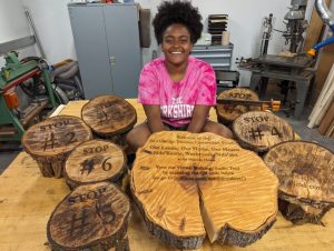
Yoheidy sits with her series of laser engraved wood slabs. She later added a laser engraved metal QR code label that directs users to the hosted video tour.

Yoheidy sits with her series of laser engraved wood slabs. She later added a laser engraved metal QR code label that directs users to the hosted video tour.

Inspiration was taken from a project recently completed by Yoheidy (Yoyo) Feliz ‘26, who engraved wood slabs to make signs for visitors going through the virtual exhibit tour at the Stockbridge-Munsee Tribe’s exhibit in Stockbridge. Those wood slabs were sourced from Hopkins Memorial Forest which is also where our project’s journey began!

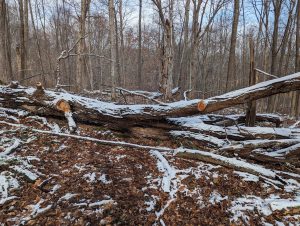
The sugar maple that provided logs for the signage

The sugar maple that provided logs for the signage

We received Sugar Maple logs claimed from the old grove across from the sugar shack with the support of Josh Sandler, Interim Hopkins Forest Manager. This tree fell two years ago, and had not yet been repurposed; the tree was part of the maple sugar grove that has a long history of being used for maple sugaring in Hopkins Memorial Forest. The logs were harvested with the help of a chainsaw by caretaker Javi Jenkins-Soresnen ‘25 who has a lot of experience in forestry.   

Logs into Lumber 

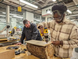
Sam Samuel '26 creating a temporary sled guide to saw logs into planks with bandsaw

Sam Samuel ’26 creating a temporary sled guide to saw logs into planks with bandsaw

Once we received the logs, we had a series of sessions in the Williams Hopper Science Shop with Makerspace Program Manager David Keiser-Clark and Instrumentation Engineer Jason Mativi. Our goal was to mill the logs into 35 planks measuring 4″x20″ with approximately a 1″ thickness. We purchased cedar posts—that had formerly been telephone polls—locally from the Eagle Lumber sawmill in Stamford, VT. In the end, we were able to create exactly 37 planks, leaving us with precious little room for error.                

Given the unevenness of the natural logs received, the first step was to build a sled (a platform) that would stabilize each log as we sliced them into planks with the bandsaw. We affixed each log to the sled with a couple screws (carefully avoiding the path of the bandsaw blade), sliced to create a flat side, then rotated the log 90 degrees and sliced again. After making two contiguous flat sides, we were able to slice the log more conveniently by using the bandsaw fence and tabletop. 

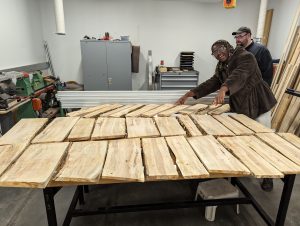
Completed lumber that was then left to dry for a week.

Completed lumber that was then left to dry for a week.

After cutting each plank, we let them dry for a week; this allowed them to shrink and to cup or curl (warp) a week. Before drying, the maple measured between 8 to 20% moisture content. Typically when letting wood dry, you want to stack your lumber with spacers to allow air flow to all sides, and allow it to dry for six months or more. Because we were short on time, we used spacers and placed weights on top of the stacks, hoping to aid them in drying flat. After a week of drying, we were able to visually see shrinkage and some warping. 

We then used the wood jointer to create one flat edge; this process created a nearly perfectly flat and square edge that was perpendicular to the wider section of the board. We then placed that flat edge against the fence of the table saw to create a second clean edge parallel to the jointed edge. We used the jointer again to create a nearly perfectly flat surface on the wide side of the board. Next we used the thickness planer to flatten the top face of the plank and be parallel with the bottom face. This work resulted in creating beautiful rectangular sugar maple planks that were both parallel and square. We repeated this process for each board.

Engraving

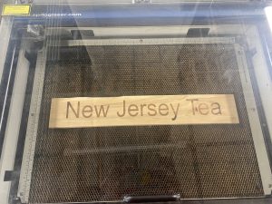
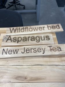
After we had jointed, sliced, and planed the maple logs into boards, Mativi and David taught me how to use the Epilog Laser Helix engraver to make a Welcome sign, informational signs for the Rain Garden, Solar Meadow, and Picking Sign, and also 31 plant identification signs. It was my first time using a laser engraver and I had to be conscious about placement, size, as well as laser power and speed. Using CorelDraw (software), I centered each sign’s text to the middle of the engraver platform, which ended up being 12 inches on the x-axis and 9 inches on the y-axis. I worried endlessly about placement and sizing so I first experimented on matboard. Despite my experimentation, I still had some underlying issues given varying thickness and placements that are evident in my very first attempts at engraving. Each laser engraving requires 15 to 20 minutes, and I often repeated that process two or three times to burn a deeper image into the wood.

Plank inside of Epilog Laser Helix after one round of engraving

Plank inside of Epilog Laser Helix after one round of engraving

First batch of completed planks for plants

First batch of completed planks for plants


Next Steps

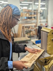
Sam Samuel '26 rounding corners with belt sander

Sam Samuel ’26 rounding corners with belt sander

I expect to complete laser engraving all of the signs within the next two weeks. The next step will be to affix the signs onto cedar posts; Jason Mativi has already cut those into 48” lengths including a spiked tip to make it easier to drive them into the ground. The final steps will include sanding the sharp corners and adding a 100% natural Walrus tung oil preservative to better show the grain and improve longevity. Because our wood is dry, we will increase the ratio of tung oil and Citra solvent from the standard 1:1 to instead be a 2:1 ratio (2 parts tung oil, 1 part citra solv) and then warm that mixture and add in beeswax (4:1 ratio of tung/citra to beeswax) for additional protection. It will be exciting to see the signs all over the Envi Center gardens! 

Postscript (May 2, 2024)

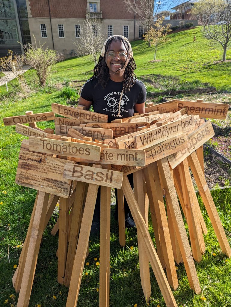
Sam Samuel '26 with 37 laser-engraved signs for the Envi Center gardens. This project was sourced from three 24" sugar maple logs from a fallen tree in Hopkins Memorial Forest,

Sam Samuel ’26 with 37 laser-engraved signs for the Envi Center gardens. This project was sourced from three 24″ sugar maple logs from a fallen tree in Hopkins Memorial Forest,

Postscript (June 21, 2024)

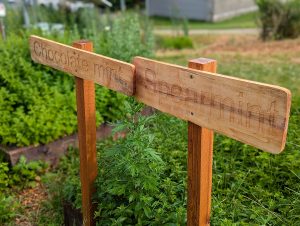
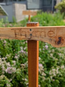
Laser-engraved signs installed in the Envi Center gardens

Laser-engraved signs installed in the Envi Center gardens

Laser-engraved signs installed in the Envi Center gardens

Laser-engraved signs installed in the Envi Center gardens

E4 Bug Off Team Project : Mitigating Japanese Beetle Damage

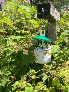
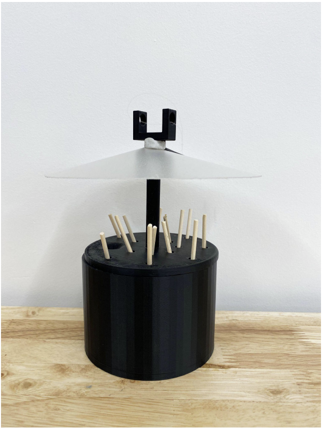
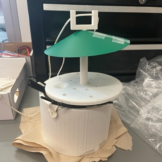
The E4 Bug Off Project: Installed in the Williams College Community Garden

The E4 Bug Off Project: Installed in the Williams College Community Garden

Japanese beetles are an invasive species that cause considerable damage to plants across much of the United States, including in the Williams College ‘66 Envi Center

gardens. The E4 Bug Off Team—consisting of students at Harvey Mudd and Pomona colleges (Javier Perez, Linna Cubbage, Betsy Ding, Eli Schwarz, and Stephanie Huang with guidance from Profs. Steven Santana and TJ Tsai)—collaborated with the Zilkha Center on the E4 Bug Off Team Project: Mitigating Japanese Beetle Damage to develop means for repelling the beetles from campus gardens and lands before they could harm the plants. The E4 Bug Off team developed a model for a physical artifact that emits repelling scents and can be attached to trees and plants. The device, which can be created by a 3D printer, is intended to be easily built, used, durable, and human and bee friendly.

E4 Team 3D Prototype and Redesign

The E4 Bug Off Teams Final Prototype


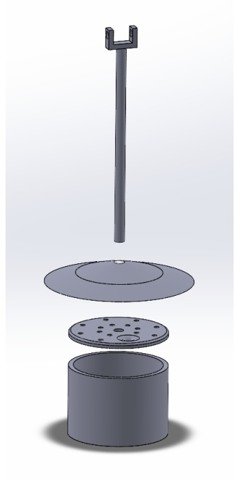
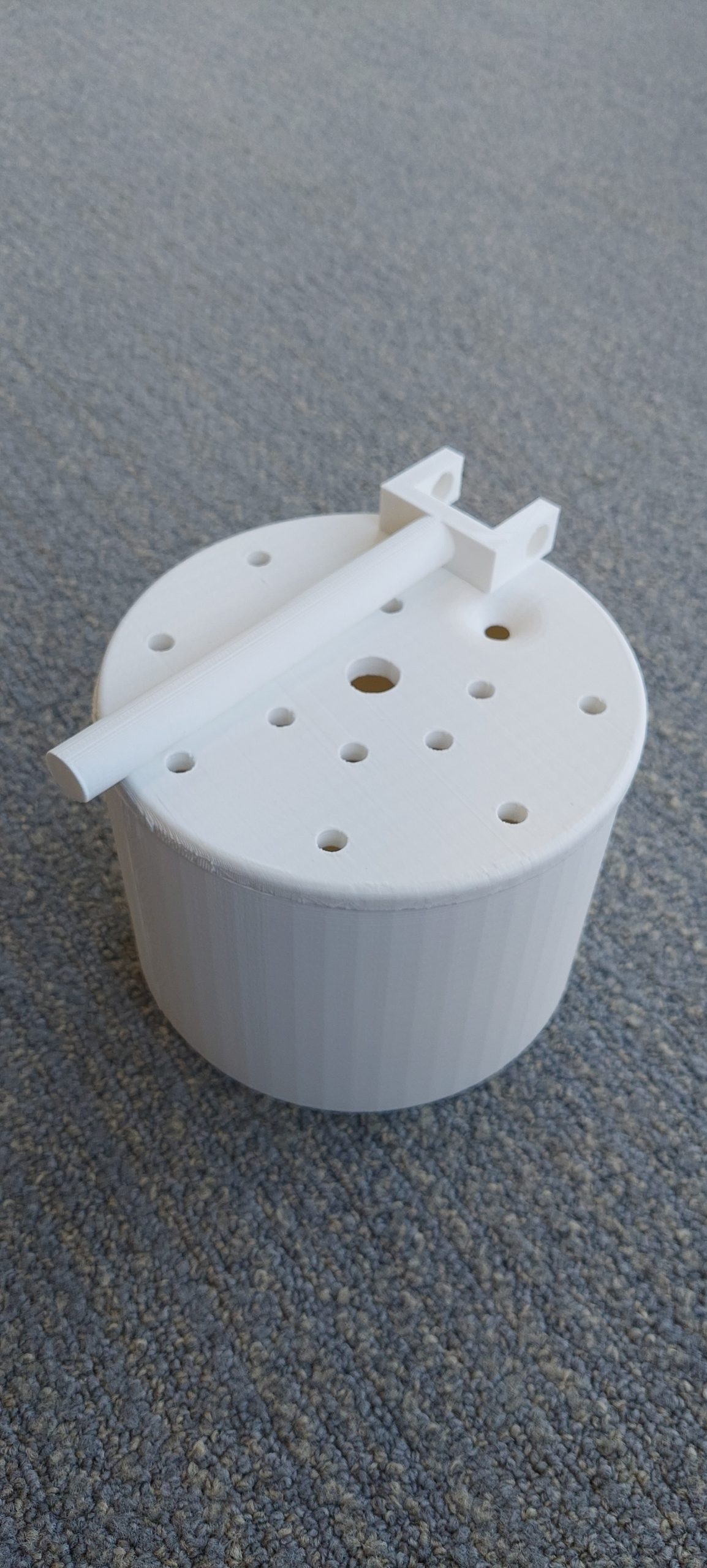
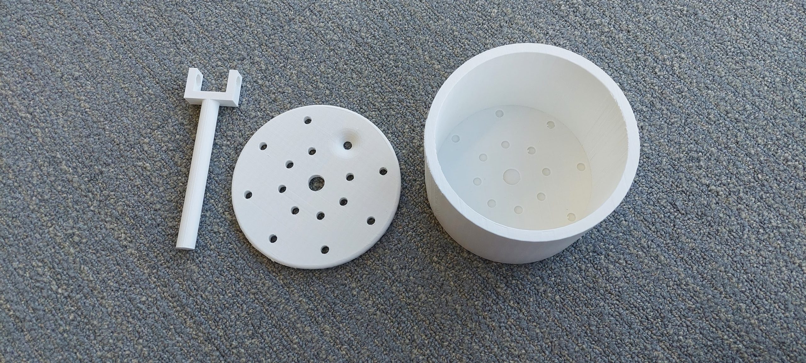
The E4 Bug Off team shared the CAD files with the Zilkha Center who asked the Williams College Makerspace for assistance with printing. The first iteration of the 3D model that was created by the Makerspace consisted of a white tall body, a lid with various holes, and a short rod. 

The holes in the lid are for peppermint-scented sticks and the tall body could hold additional scent liquid. Based on the research done by the E4 Bug Off team, peppermint scent was found to be a repellent of Japanese Beetles. Thus, if the scent is widely enough dispersed by the wind, it should help with keeping Japanese beetles from the area around the device. It remains to be tested, how many devices will be needed to cover the area of the gardens. It’s an innovative solution since peppermint is safer than other traps such as spectracide bags, which have low to moderate toxicity for humans. It has also been reported that such bags may also simply increase the numbers of beetles present.

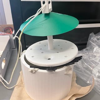
The artifact also features a green cone, which protects the scent sticks from rain. It was cut out of a plastic folder by the Zilkha Center summer garden interns. 

Zilkha Center: Beetle model 3D printed and built following the E4 Bug Off Team’s CAD files

The first prototype had a few shortcomings: its body was leaky and the rod was a little too big to fit into the lid. Zilkha Center garden interns, Martha Carlson and Evan Chester, put putty on the holes in the body to stop it from leaking and needed to heavily sand down the rod for it to fit in the base. 

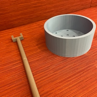
To create a longer-lasting solution that could also be printed in larger numbers, a new body and slightly thinner rod were designed and reprinted. 

The plan is to launch the device in time for the summer 2023 Japanese Beetle season, assuming all goes well with the new sealing method. The Makerspace and Zilkha Center will share the final 3D design and list of ingredients after the final testing is complete.

New body and thinner rod

New body and thinner rod