Polyformer Updates:
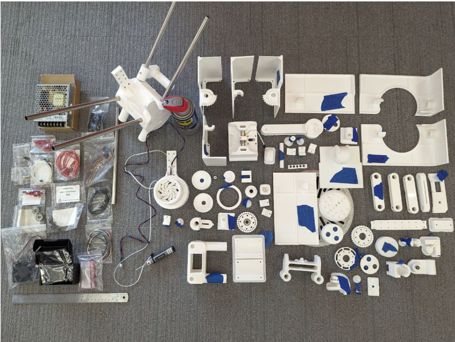
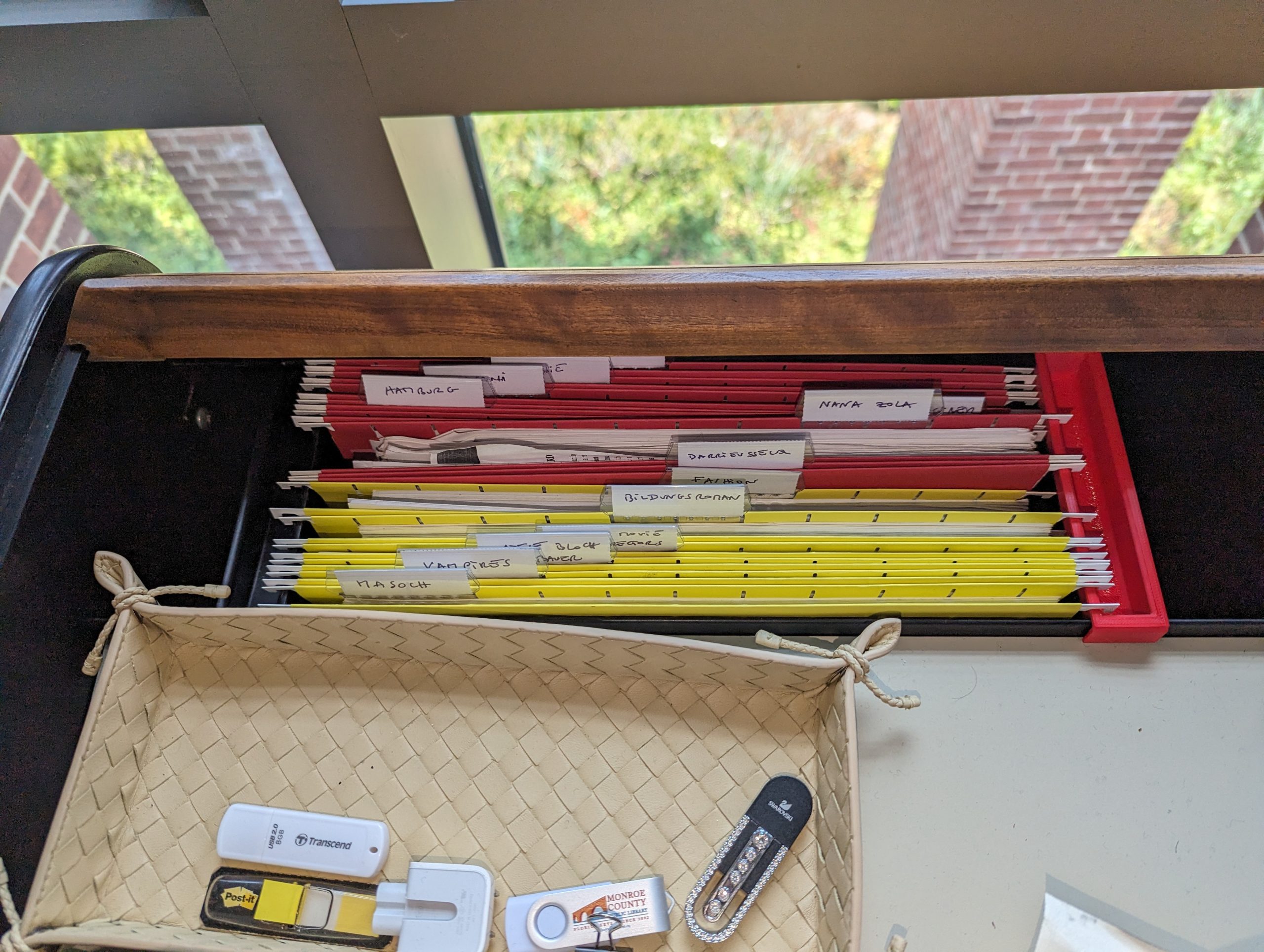
Polyformer 3D printed parts and electronics ready to be assembled.
My name is Camily Hidalgo Goncalves, and I am a sophomore at Williams College majoring in Chemistry with a Neuroscience concentration. As a Makerspace student worker, I have recruited Milton Vento ’26, Tashrique Ahmed ’26 (both Computer Science students at Williams College and fellow Makerspace student workers), and Oscar Caino ’27, a student at Swarthmore College who is a prospective Engineering major, to assist me in assembling the Polyformer parts and electronics. We have completed several milestones, and made significant progress on the Polyformer project at Williams College. This innovative project aims to upcycle waste plastic bottles into locally-sourced 3D printer filament.
Assembly and Integration
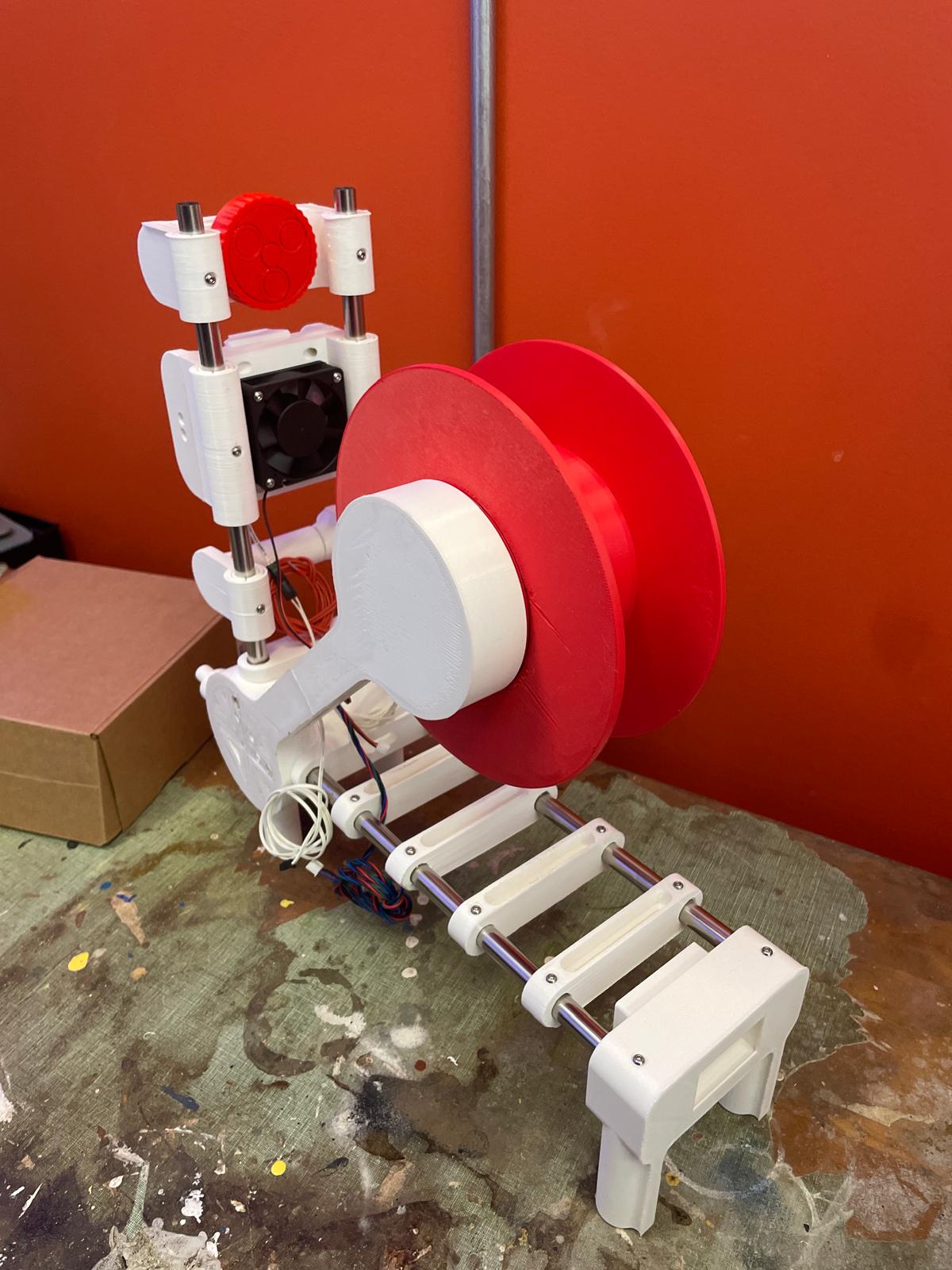
The assembled Polyformer
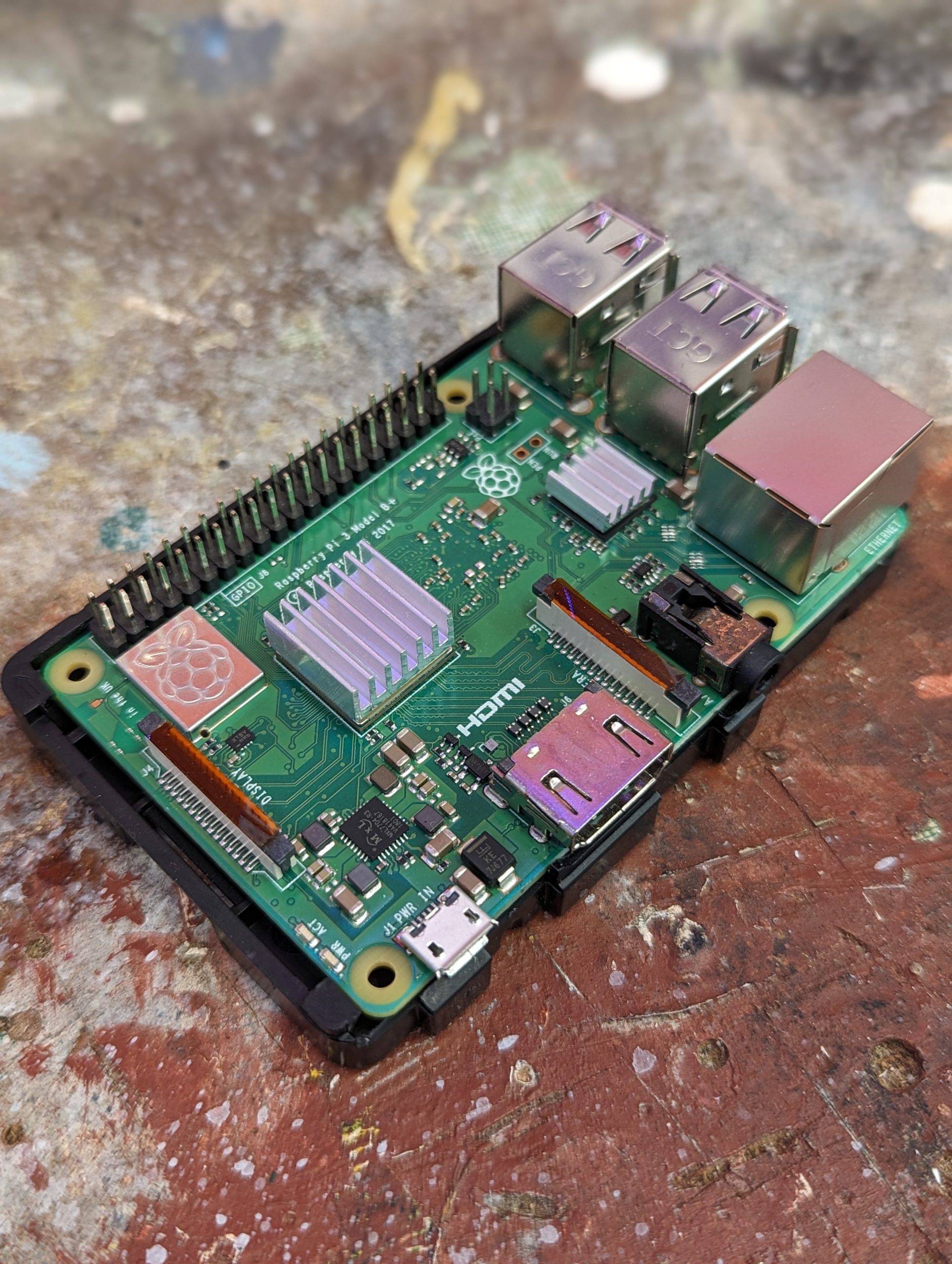
Milton, Oscar and I worked together to assemble the 78 individual 3D-printed parts required for the Polyformer. This intricate process demanded precision and teamwork. Following the assembly of the physical components, I assisted Tashrique with integrating the electronics. This included the installation of a circuit board, LCD screen, volcano heater block, stepper motor, and various sensors and wiring. These components are essential for the Polyformer to function effectively, converting plastic bottles into usable 3D printer filament.
Collection and Processing of Plastic Bottles
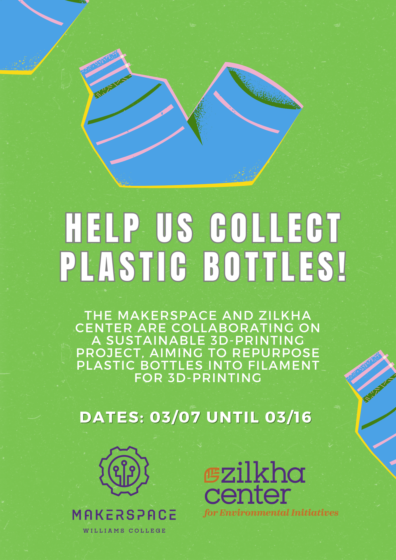
Plastic bottle collection poster.
In preparation for testing, we collected approximately 75 plastic bottles. These bottles were contributed by the Williams College community, demonstrating a collective effort to reduce plastic waste. Elena Sore ‘27, a prospective Computer Science major and Makerspace student worker, and I worked on the initial step in the processing phase, which involved us cleaning the bottles and cutting them into long, consistent ribbons. These plastic ribbons will then be fed into the Polyformer, where they will be melted and extruded into filament.
Testing and Quality Assurance
Next fall semester we will begin rigorous testing to ensure that the Polyformer operates smoothly and produces high-quality filament that meets the required standards for 3D printing. Several tests will be conducted, including:
- Durability Testing: Assessing the strength and flexibility of the produced filament.
- Consistency Testing: Ensuring the filament has a uniform diameter, which is crucial for reliable 3D printing.
- Compatibility Testing: Verifying that the filament performs well with various 3D printers and printing conditions, while accommodating different material thicknesses from various brands of PET bottles.
Project Goals and Benefits
The Polyformer project aligns with Williams College’s sustainability goals and offers numerous benefits:
- Waste Reduction: By upcycling plastic bottles, we reduce the amount of plastic waste that ends up in landfills or oceans.
- Sustainability Education: The project serves as a hands-on educational tool, teaching students about the importance of repurposing and innovative ways to repurpose waste materials.
- Local Impact: The filament produced will be used to create practical items such as plant pots and compost bins for the Zilkha Center for Environmental Initiatives, supporting local sustainability efforts.
Next Steps
We hope to create a sustainable cycle of converting plastic waste into useful products, while minimizing the environmental impact of plastic disposal. This project provides practical solutions to plastic waste, and also serves as an educational tool, raising awareness about sustainability and encouraging innovative thinking in environmental conservation.
As we move forward, our next steps will be to refine the process and increase the efficiency of the Polyformer:
- Rigorous Testing: Thoroughly test the Polyformer to ensure it produces reliable and high-quality filament that meets 3D printing standards.
- Scaling Up: Increase the number of collected bottles and the quantity of filament produced.
- Educational Workshops: Host campus workshops to educate the broader community about the Polyformer and the importance of sustainable practices. We might seek to collaborate with the Williamstown Milne Library to host a workshop for local community members.
- Research and Development: Continue to improve the design and functionality of the Polyformer based on feedback and test results.
Acknowledgements
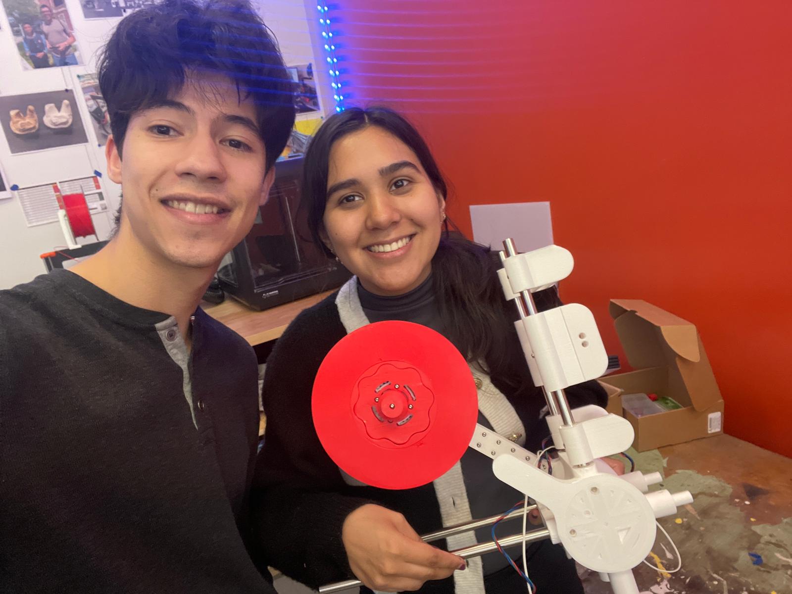
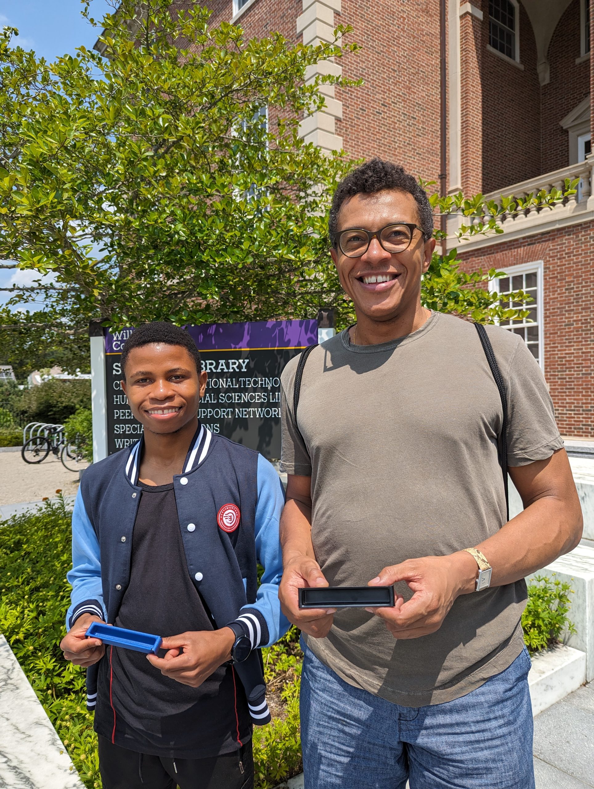
Assembling the Polyformer: Oscar Caino ‘27, a Swarthmore College student (left), and Camily Hidalgo Goncalves ‘26, a Williams College student (right).
This project would not have been possible without the ongoing support and collaboration received. We are immensely grateful to our collaborators: David Keiser-Clark (Makerspace Program Manager), Milton Vento ‘26, Tashrique Ahmed ‘26 and Elena Sore ‘27 (Makerspace Student Workers), Yvette Belleau (Lead Custodian, Facilities), Christine Seibert (Sustainability Coordinator, Zilkha Center), Mike Evans (Deputy Director, Zilkha Center for Environmental Initiatives), and Oscar Caino ‘27 (Swarthmore College Student). Their expertise, guidance, and contributions have been invaluable to the progress of the Polyformer project.
Stay tuned for more updates as we continue to develop and test the Polyformer. Together, we can make a significant impact in reducing plastic waste and promoting sustainable practices at Williams College.