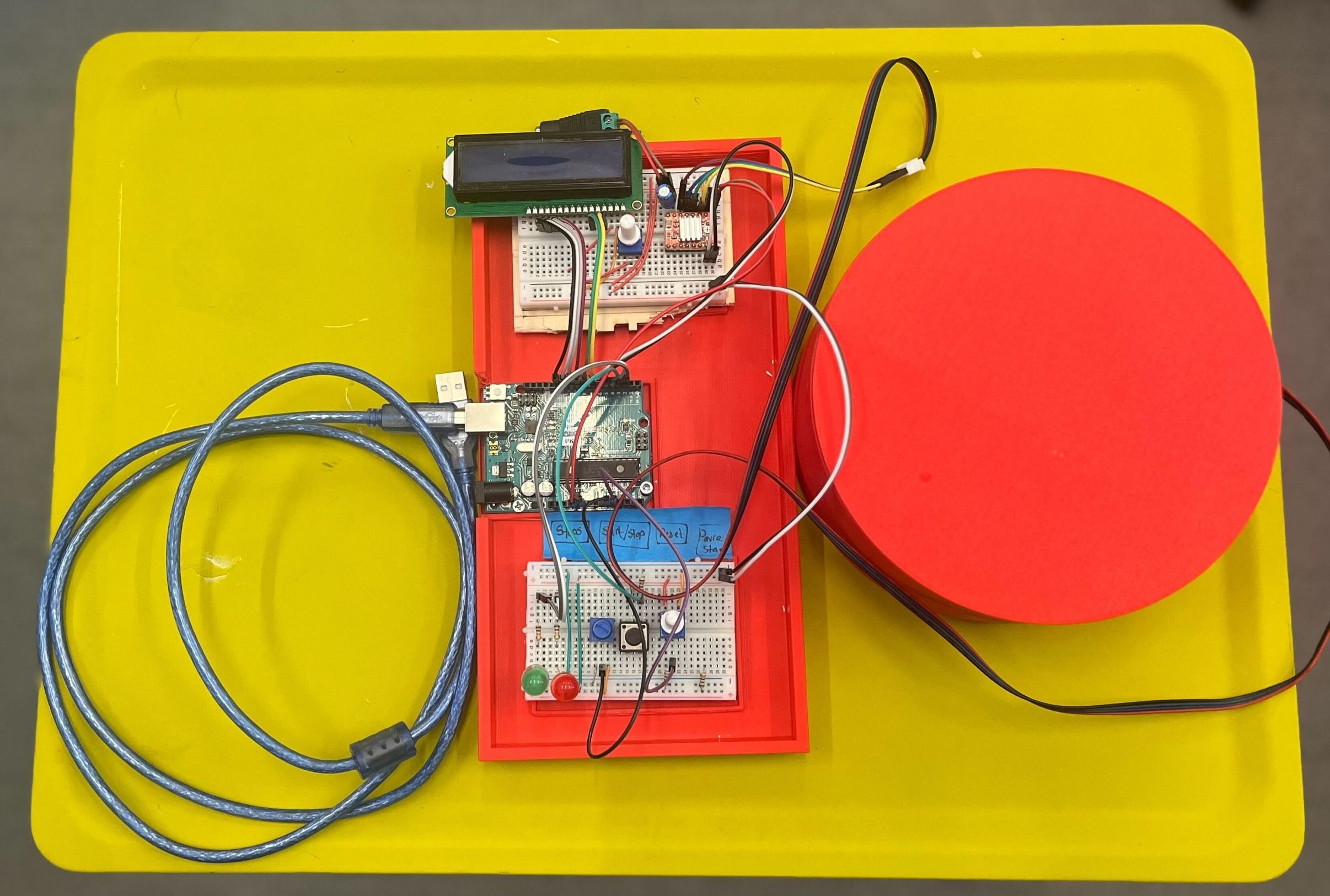
Completed Turntable with the control board
Welcome back to my deep dive into the creation of a low-cost DIY Arduino turntable designed for photogrammetry enthusiasts. In this continuation, I will share a detailed, step-by-step breakdown of the build process, highlighting the technical challenges and solutions, while providing comprehensive resources to empower you to replicate this project.
Components
The primary goal was to design a reliable and cost-effective turntable that can be easily assembled by hobbyists. The focus was on using readily available parts and open-source software to keep the project accessible. Below is a detailed component breakdown, including links, for each part needed, for the project:
1. NEMA 17 Stepper Motor
Quantity: 2-3
Why? Chosen for its balance between cost and performance. NEMA 17 offers sufficient torque for precise rotations necessary in photogrammetry without being overly robust for lightweight platform applications. Compared to larger steppers like the NEMA 23, which offers more power but at a higher cost and size, the NEMA 17 is more suited for desktop projects where space and budget are limited.
2. A4988 Stepper Motor Driver
Quantity: 2-3
Why? The A4988 is a reliable and widely used motor driver that offers easy interfacing with Arduino, making it ideal for beginners and intermediate users alike. It supports micro-stepping which is essential for smooth and accurate rotation. Other drivers like the DRV8825 could also be used but typically cost more and require additional adjustments, making the A4988 a more straightforward choice for this project.
3. 608 Bearing 8x22x7
Quantity: 4-6
Why? These standard skateboard bearings are cost-effective and easily available. They are durable and provide smooth rotation with minimal friction, which is crucial for the accuracy of the turntable. Alternative options like specialized robotics bearings offer higher precision but at a significantly higher cost, making them overkill for this application.
4. 12V Adapter with Female Adapter
Quantity: 1
Why? This adapter provides a reliable and stable power source for the project. 12V is typically needed for the stepper motors, and using a dedicated adapter ensures consistent performance. Alternatives like USB power sources do not generally offer sufficient current for larger motors and can lead to performance issues.
5. Male – Male Jumper Wires
Quantity: 1 pack
Why? Essential for making connections between the Arduino, motor driver, and other components. Chosen for their flexibility and ease of use, they can be quickly reconfigured as needed without soldering, making prototyping faster and simpler. Compared to other connectors, these are very cost-effective and work well in a breadboard setup.
6. Breadboard
Quantity: 1
Why? A breadboard is ideal for this type of project because it allows for easy adjustments and experimentation without permanent changes. This medium-sized breadboard was selected for its sufficient size to fit all components while remaining compact, offering a balance between workspace and portability. I do have plans for using a PCB board in future iterations. More details on it later.
7. Arduino Uno R3
Quantity: 1
Why? The Arduino Uno R3 is the standard for many DIY electronics projects due to its robust community support, extensive libraries, and compatibility with a wide range of shields and accessories. It strikes an ideal balance between functionality, price, and user-friendliness, making it preferable over more powerful boards like the Arduino Mega when simplicity and cost are considered.
8. Push Buttons
Quantity: 3
9. 330 Ohm Resistors
Quantity: 4
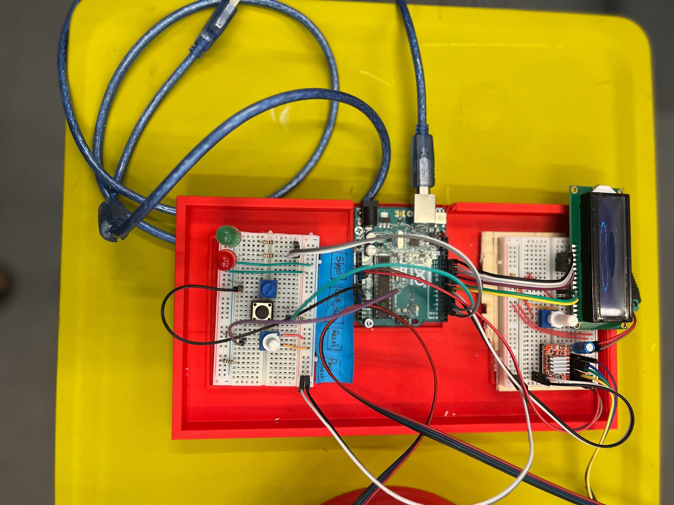
The control board
STL Files
For each part, I’ve created STL files that you can download and print. The files are designed to be printed with common filament materials like PLA or ABS, which offer a good balance between strength and ease of printing. You can download the .stl files from: https://github.com/tashrique/DIY-Turntable-Makerspace-Resources.
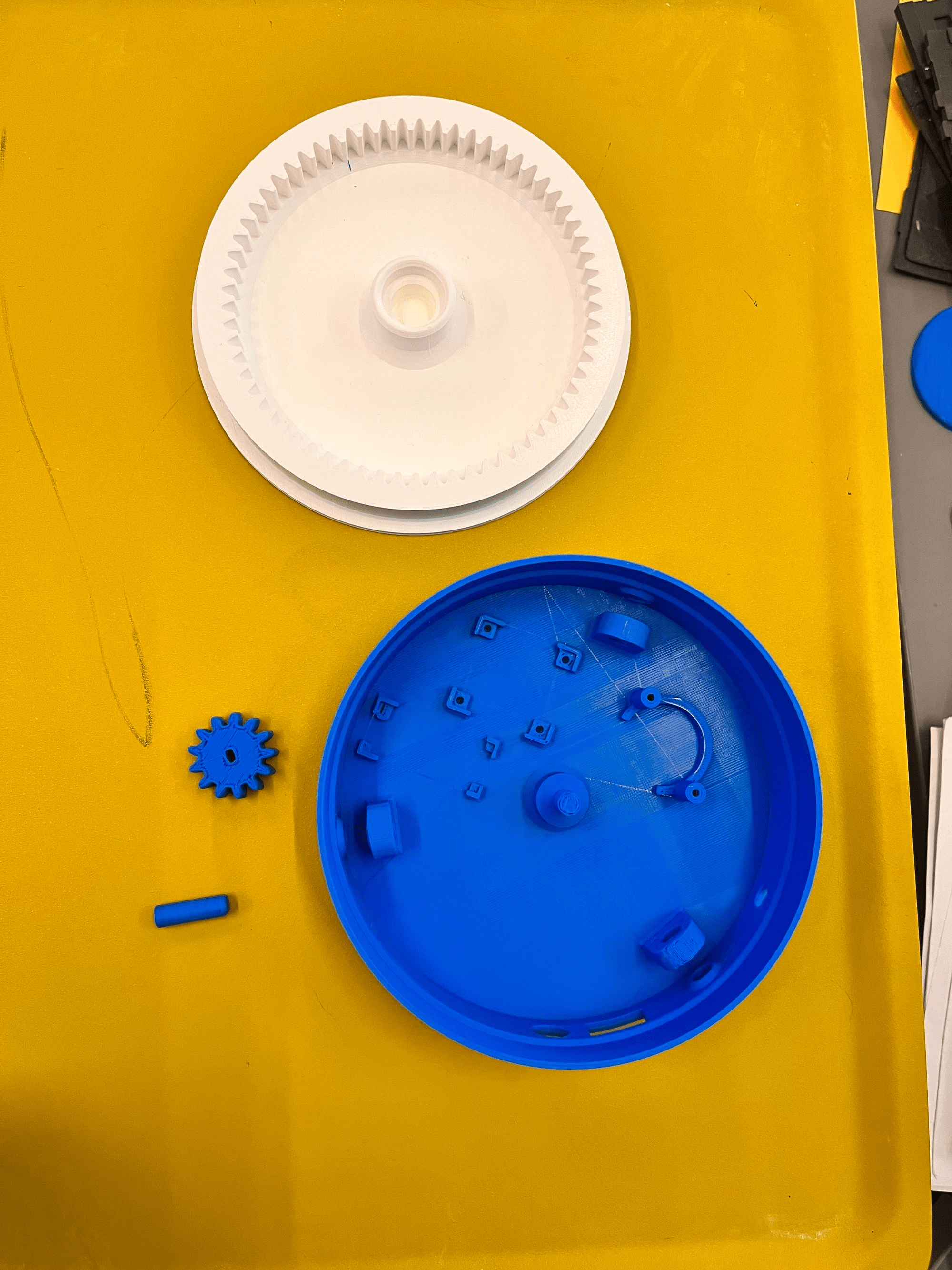
- Base V2: This is the foundation of the turntable. It holds the stepper motor and the bearings.
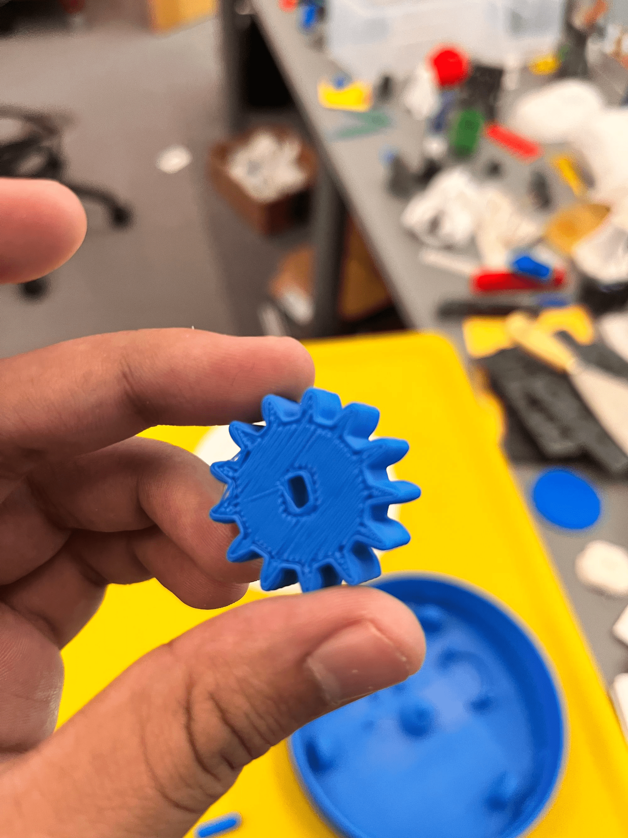
- Rotating Platform V2: This part is mounted on top of the bearings and is directly driven by the stepper motor. It is where the object to be scanned is placed.
- Bearing Holders: These components are used to hold the 608 bearings in place. Print 3 pieces of these.
3D Printing Instructions
- Material: PLA, PETG, ABS, or ASA
- Layer Height: 0.2 mm for a good balance of speed and detail.
- Infill: 15% is sufficient for structural integrity but can be increased for parts under more stress, like the motor mount and gear set.
- Supports: All parts should print well without supports.
- Bed Adhesion: Use a raft or brim if you experience issues with bed adhesion during printing.
Assembly Tips
Once the parts are printed, follow these tips for assembly:
- Before the final assembly, test fit all parts together. This helps identify any print errors or adjustments needed.
- If some parts don’t fit perfectly, you may need to sand or trim them slightly.
- Use appropriate screws and adhesive to secure the parts firmly. This ensures the turntable remains stable during operation.
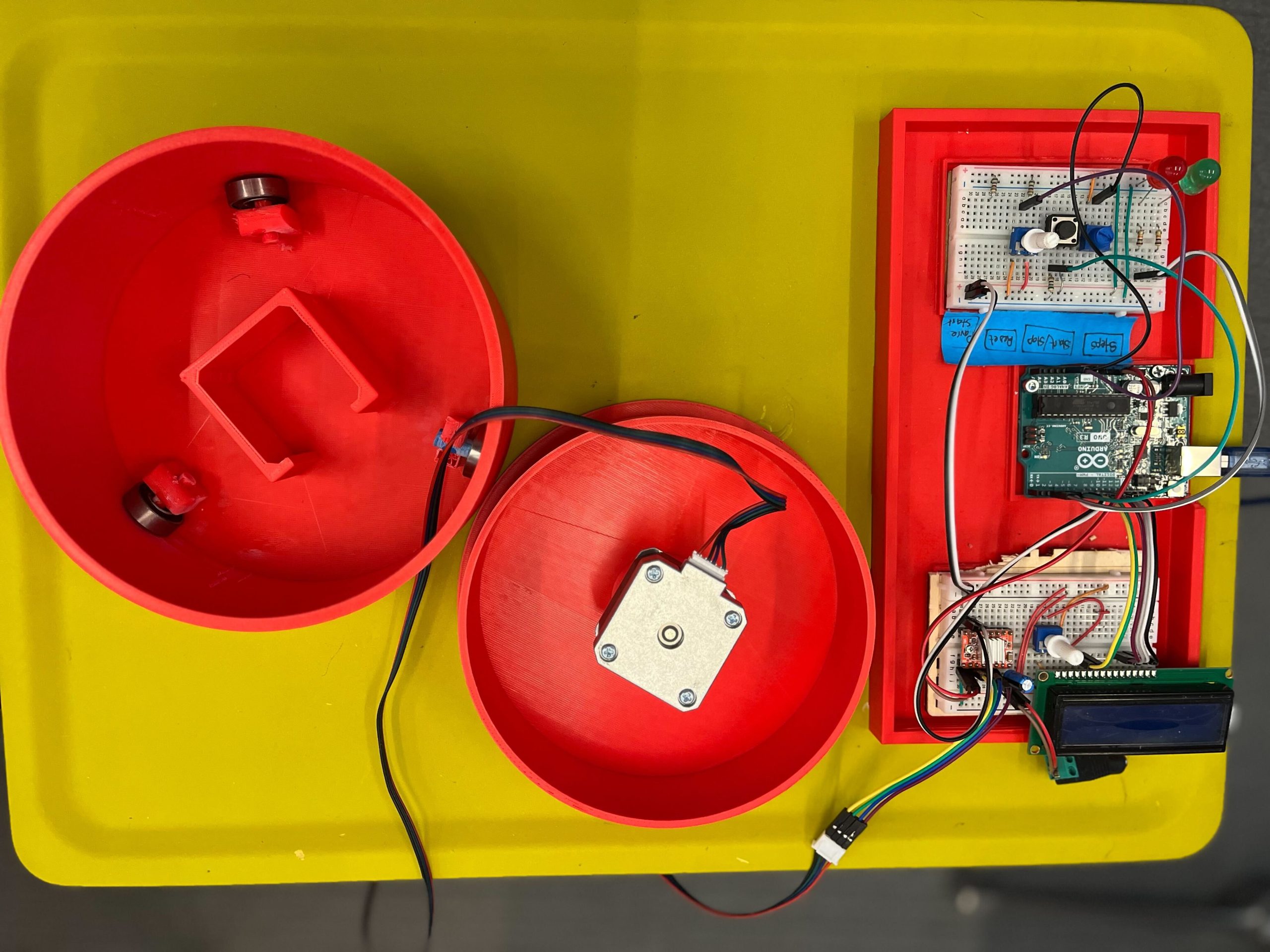
Completed assembly of the turntable
Assembly Process
Assembly Process for the Non-Electronic Components
Tools and Materials Needed
- Super Glue (optional, for additional stability)
- Sand Paper (optional, to make edges smooth)
Step 1: Preparing the Base Plate
- Start by preparing the base plate, clear the base plate of any excess material from printing.
Step 2: Installing the Motor
- Align the motor mount with the designated area on the base plate.
- Slide the motor into the slot
- Ensure the motor shaft protrudes through the mount to align with the gear system.
Step 3: Setting Up Bearings
Objective: Install the bearings that will support the rotating platform.
- Position the bearing holders on the base plate as per the design.
- Insert the 608 bearings into the holders. If the fit is tight, you may gently tap them into place using a rubber mallet. You might also want to use superglue to secure the holders in place.
- Ensure the bearings spin freely without obstruction.
Step 4: Installing the Rotating Platform and Connecting the motor
- Carefully align the rotating platform with the top of the bearings.
- Slide and apply moderate pressure to put the motor shaft in the connector until it is stable and level.
- Check that it rotates smoothly without catching or excessive play.
Step 5: Final Adjustments and Testing
- Manually rotate the platform to check for smooth motion and correct gear alignment.
- Make any necessary adjustments to the tightness of screws or alignment of gears.
- Optionally, apply a small amount of lubricant to the gears and bearings for smoother operation.
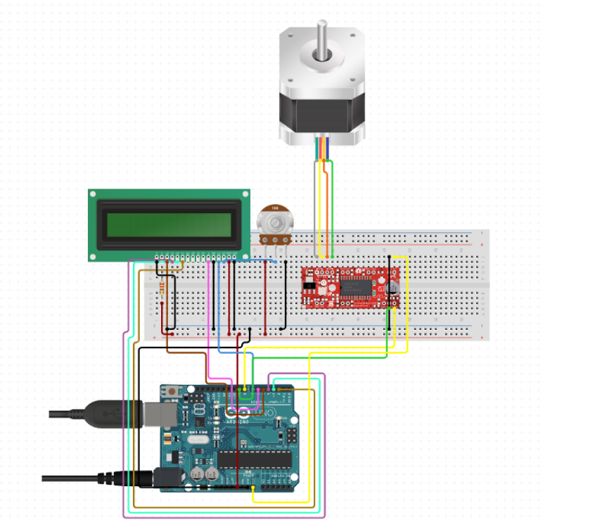
Schematic diagram of the electronic components and pin connections
Electronic Assembly Guide
Tools and Materials Needed
- Wire Cutters
- Wire Strippers
- Soldering Iron (optional, for a more permanent setup)
- Multimeter (for checking connections)
Step 1: Setting Up the Arduino
Objective: Prepare the Arduino board for connection.
- Place the Arduino on your workbench or mount it on the base plate.
- Ensure that it is accessible for connections to both power and other components like the LCD and stepper motor driver.
Step 2: Connecting the Stepper Motor Driver
Objective: Install the A4988 stepper motor driver (Tip: stepper driver documentation).
- Connect the motor driver to the Arduino using male-to-female jumper wires. Here’s a basic pin connection guide:
- Connect the DIR (Direction) pin on the driver to a chosen digital pin on the Arduino (e.g., D2).
- Connect the STEP pin on the driver to another digital pin on the Arduino (e.g., D3).
- Ensure ENABLE pin is connected if your driver requires it, otherwise it can be left unconnected or tied to ground.
- Connect the VDD on the A4988 to the Arduino’s 5V output, and GND to one of the Arduino’s ground pins.
Step 3: Wiring the Stepper Motor
Objective: Connect the NEMA 17 stepper motor to the A4988 driver (Tip: NEMA17 documentation).
- Identify the wire pairs of the stepper motor using a multimeter or by referring to the motor’s datasheet.
- Connect these wires to the respective A and B terminals on the motor driver. Ensure that the polarity matches the driver’s requirements.
- Double-check the connections to prevent any potential damage due to incorrect wiring.
Step 4: Adding the LCD Display
Objective: Connect the 16×2 LCD to the Arduino to display status and control messages.
- Use a breadboard or direct jumper wires to connect the LCD. Typical connections are:
- RS (register select) to a digital pin (e.g., D4).
- E (enable) to another digital pin (e.g., D5).
- D4 to D7 data pins of the LCD to digital pins D6, D7, D8, D9 on the Arduino.
- Connect the VSS pin of the LCD to the ground and VDD to 5V on the Arduino.
- Connect a potentiometer to the VO (contrast adjust) pin for contrast control.
Step 5: Power Supply Connection
Objective: Ensure proper power supply connections.
- Connect the 12V adapter to the VMOT and GND on the stepper motor driver to power the stepper motor.
- Ensure the Arduino is powered either via USB or an external 9V adapter connected to the VIN pin.
Step 6: Testing and Debugging
Objective: Test the setup to ensure everything is working as expected.
- Upload a simple test sketch to the Arduino to check motor movements and LCD functionality.
- Adjust the potentiometer to get a clear display on the LCD.
- Use the multimeter to troubleshoot any connectivity issues.
Step 7: Final Setup
Objective: Secure all electronic components and clean up the wiring.
- Use zip ties or cable management clips to organize and secure wires.
- Ensure all connections are stable and that there’s no risk of loose wires interfering with the moving parts.
Wiring Diagram
LCD Pin Mapping
Reset = 7;
Enable = 8;
D4 = 9;
D5 = 10;
D6 = 11;
D7 = 12;
Stepper Motor Pin Mapping
Step = 6
Direction = 5
(Type of driver: with 2 pins, STEP, DIR)
Programming the Turntable
#include <LiquidCrystal.h>
#include <AccelStepper.h>

void(* resetFunc) (void) = 0;

/*
LCD Pin Map
Reset = 7;
Enable = 8;
D4 = 9;
D5 = 10;
D6 = 11;
D7 = 12;

Stepper PIN Map
Step = 6
Direction = 5
(Type of driver: with 2 pins, STEP, DIR)

*/


AccelStepper stepper(1, 6, 5);

const int rs = 7, en = 8, d4 = 9, d5 = 10, d6 = 11, d7 = 12;
LiquidCrystal lcd(rs, en, d4, d5, d6, d7);

int green = 2;
int red = 3;
int button = 4;
int controls = A1;
int speeds = A0;


String currentStat = "Reset";
String prevStat = "Reset";
int stepsTaken = 0;
bool buttonPressed = false;
bool actionTaken = false;
int buttonClicked = 0;
int currentSpeed = 0;


void setup() {
lcd.begin(16, 2);
pinMode(green, OUTPUT);
pinMode(red, OUTPUT);
pinMode(button, INPUT);

resetControls();
}


void loop() {
runProgram();
}

void runProgram() {
currentSpeed = readSpeed();
currentStat = getStatus();
buttonClicked = buttonClick();

digitalWrite(red, HIGH);

lcd.setCursor(0, 0);
lcd.print(": " + currentStat);

lcd.setCursor(8, 0);
lcd.print("-> " + String(currentSpeed) + "ms");


if (buttonClicked == 1) {
lcd.clear();

//Reset
if (currentStat == "Reset") {
lcd.setCursor(0, 0);
lcd.print("RESETTING...");
stepsTaken = 0;
prevStat = currentStat;
digitalWrite(green, LOW);
digitalWrite(red, HIGH);
resetFunc();
}

//Resume
else if (currentStat == "Start" && prevStat == "Pause") {
lcd.setCursor(0, 1);
lcd.print("RESUMED @" + String(currentSpeed));
prevStat = currentStat;
stepsTaken = commandStart(currentSpeed, stepsTaken);
}


//Start
else if (currentStat == "Start") {
lcd.setCursor(0, 1);
lcd.print("STARTED @" + String(currentSpeed));
prevStat = currentStat;
stepsTaken = commandStart(currentSpeed, 0);
}

else if (currentStat == "Pause" && prevStat == "Pause") {
lcd.setCursor(0, 1);
lcd.print("Already Paused");
}

//Undefined
else {
lcd.setCursor(0, 1);
lcd.print("Invalid Command");
}
}
}


/*--------------------------------------*/

int commandStart(int currentSpeed, int initial) {

lcd.clear();
int steps = 0;

digitalWrite(red, LOW);
digitalWrite(green, HIGH);

for (int i = initial; i <= 200; i++) {
stepper.moveTo(i);
stepper.runToPosition();
lcd.setCursor(0, 1);
lcd.print(i);

lcd.setCursor(4, 1);
lcd.print("/ 200 steps");
steps = i;
delay(currentSpeed);


//Check if any other button is pressed while started
String check = getStatus();
lcd.setCursor(0, 0);
lcd.print(check);

int clicked = buttonClick();
String clickedIndicator = clicked ? "*" : "";
lcd.setCursor(6, 0);
lcd.print(clickedIndicator);

if (clicked) {
if (check == "Reset") {
lcd.clear();
lcd.setCursor(0, 0);
lcd.print("RESETTING...");
delay(200);
stepsTaken = 0;
prevStat = "Reset";

digitalWrite(green, LOW);
digitalWrite(red, HIGH);

resetFunc();
}

else if (check == "Pause") {
lcd.clear();
lcd.setCursor(0, 0);
lcd.print("Paused");
delay(200);
prevStat = "Pause";

digitalWrite(green, HIGH);
digitalWrite(red, HIGH);
return steps;
}
}
}

return steps;
}

/*--------------------------------------*/

int buttonClick()
{
int reading = digitalRead(button);
return reading;
}


void resetControls() {
lcd.clear();
lcd.setCursor(0, 0);
lcd.print("Turntable - Tash!");
digitalWrite(red, HIGH);
digitalWrite(green, HIGH);
delay(500);
digitalWrite(red, LOW);
digitalWrite(green, LOW);
delay(500);
digitalWrite(red, HIGH);
digitalWrite(green, HIGH);
delay(500);
digitalWrite(red, LOW);
digitalWrite(green, LOW);
lcd.clear();
}


String getStatus() {
int controlStatus = analogRead(controls);
int controlRange = map(controlStatus, 0, 1023, 1, 4);
String stat = "";

if (controlRange == 1)
stat = "Reset";

else if (controlRange == 2)
stat = "Pause";

else if (controlRange == 3 || controlRange == 4)
stat = "Start";

else
stat = "-----" ;
delay(100);

return stat;
}


int readSpeed() {
int sensorVal = analogRead(speeds);
int stepSpeed = map(sensorVal, 0, 1023, 250, 5000);
return stepSpeed;
}
The code for the turntable is structured to handle various functionalities: controlling the motor, updating the LCD display, and reading inputs from the rotary encoder. Access the full commented code my GitHub repository: https://github.com/tashrique/DIY-Turntable-Makerspace-Resources
Troubleshooting Common Issues
Motor Noise or Vibration
- Check alignment of gears and ensure the stepper driver is correctly calibrated.
LCD Display Issues
- Verify wiring connections and contrast settings; adjust the potentiometer if used or calibrate the voltage divider correctly for clear visibility.
Code Bugs
- Use serial debugging to monitor outputs and verify that the logic in your sketches matches the intended functions.
Future Enhancements
Integration of IR Sensors
- Automate the camera shutter operation in sync with the turntable’s rotation to facilitate overnight operations.
PCB Board
- Integrate all the circuit in a PCB Board
Conclusion
If you have read this far, thank you and good luck! This guide aims to equip you with all the knowledge needed to create and customize your own turntable, fostering further exploration into the fascinating world of DIY electronics. Feel free to share your project progress and reach out with questions or suggestions. Your feedback helps improve and inspire future projects!